
Subscribe to Our Youtube Channel
Related Manuals for Endress+Hauser Analytik Jena APU 28 Series


Summary of Contents for Endress+Hauser Analytik Jena APU 28 Series
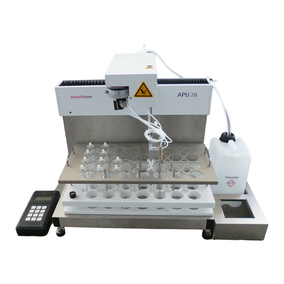
- Page 1 Operating Manual APU 28 Series AOX Sample Preparation Systems with control unit connect...
- Page 2 Manufacturer Analytik Jena GmbH Konrad-Zuse-Straße 1 07745 Jena / Germany Phone: +49 3641 77 70 Phone: +49 3641 77 9279 Mail: info@analytik-jena.com Technical Service Analytik Jena GmbH Konrad-Zuse-Straße 1 07745 Jena / Germany Phone: +49 3641 77 7407 Fax: +49 3641 77 9279 Email: service@analytik-jena.com For a proper and safe use of this product follow the instructions.
-
Page 3: Table Of Contents
APU 28 Series Table of contents Table of contents 1 Basic information ..............................About this manual ............................Intended use ..............................2 Security ................................. Safety labeling on the device ........................... Requirements for the operating personnel..................... Safety instructions for transport and commissioning..................Safety instructions: during operation ...................... - Page 4 Table of contents APU 28 Series 7 Transport and storage ............................52 Transport................................52 Preparing the device for transport........................52 Moving the device in the laboratory........................ 53 Storage ................................54 8 Disposal ................................55 9 Specifications................................ 56 Technical data..............................56 Standards and directives ..........................
-
Page 5: Basic Information
APU 28 Series Basic information Basic information About this manual These operating instructions describe the sample preparation systems of the APU 28 with the APU 28/1 S and the APU 28/1 SPE as well as their operation with the control unit connect. -
Page 6: Intended Use
Basic information APU 28 Series Intended use The sample preparation systems of the APU 28 are used for the automated enrichment of adsorbable organically bound halogens (AOX) in aqueous solutions on activated car- bon. The sample preparation systems work according to the column method according to DIN EN ISO 9562, EPA1650C, EPA9020B and others. -
Page 7: Security
APU 28 Series Security Security For your own safety and to ensure error-free and safe operation of the device, please read this chapter carefully before commissioning. Observe all safety instructions listed in this user manual and all messages and infor- mation displayed on the monitor by the control and analysis software. -
Page 8: Requirements For The Operating Personnel
Security APU 28 Series Mandatory signs/ Meaning Comment information sym- bols Disconnect the power At power supply: Before opening the supply before opening device cover, switch off the device and the device cover disconnect the mains plug from the mains socket. Observe the operating On the mains switch: Before starting manual... -
Page 9: Safety Instructions: During Operation
APU 28 Series Security Risk of damage to health due to improper decontamination! Perform a profes- ¡ sional and documented decontamination of the device before returning it to An- alytik Jena. The decontamination report is available from Service when register- ing the return. -
Page 10: Handling Of Auxiliary And Operating Materials
Security APU 28 Series Electrical connection cables between the basic module and the system compo- ¡ nents may only be connected or disconnected when the device is switched off. ¡ Ensure that no liquid enters the interior of the device, for example at cable con- nections. -
Page 11: Behavior During Emergencies
APU 28 Series Security All maintenance and repair work on the device must only be carried out when ¡ the device is switched off (unless specified otherwise). ¡ Use only original spare parts, wear parts and consumables. They have been tested and ensure safe operation. -
Page 12: Function And Design
Function and design APU 28 Series Function and design Functionality The sample preparation systems of the APU 28 enrich adsorbable organically bound halogens (AOX) on activated carbon. The devices operate according to the column method (in accordance with DIN EN ISO 9562, EPA1650C, EPA9020B) and prepare up to 28 aqueous samples fully automatically for AOX determination. -
Page 13: Fig. 3 Aox Adsorption Diagram
APU 28 Series Function and design Fig. 3 AOX adsorption diagram 1 Dosing head 2 Duplex column 3 Aspiration needle 4 Sample in sample vessel The device then rinses the loaded activated carbon in the duplex column with an acidic nitrate rinsing solution (pH ≈ 1.7) in order to remove inorganic chlorine compounds (matrix). -
Page 14: Fig. 4 Placement Diagram For Spe-Aox Samples
Function and design APU 28 Series Insoluble inorganic and organic halogen compounds and halogens adsorbed on solids are not detected by this method. Samples containing particles must be filtered before adsorption. As the placement diagram shows, one SPE-AOX sample preparation occupies two sam- ple locations on the tray at a time. -
Page 15: Design
APU 28 Series Function and design Fig. 6 Diagram of the SPE-AOX method 1 SPE column conditioning 2 Sample application on SPE column 3 AOX desorption from SPE column 4 AOX application on duplex column Step 1 serves the preparation. The device conditions the SPE column with methanol. In the further course, the SPE column does not run dry. -
Page 16: Fig. 7 Single-Channel System Apu 28 Connect Spe Comprising Basic Device Apu 28/1 Spe And Control Module
Function and design APU 28 Series The rack has a drainage channel through which residues of the sample and the rinsing solution drain into the waste canister. Before starting a sample preparation process, it is necessary to adjust movements of the sampler arm to the rack or to check the adjust- ment. -
Page 17: Fig. 8 Double Channel System Apu 28/1 S With 2 Dosing Heads And Needles
APU 28 Series Function and design Fig. 8 Double channel system APU 28/1 S with 2 dosing heads and needles Single channel system APU With the single channel system you can enrich SPE-AOX samples as well as AOX sam- 28/1 SPE ples. -
Page 18: Fig. 10 Column Flexibility Rack For Alternative Columns
Function and design APU 28 Series The APU 28 connect SPE device configuration contains the APU 28/1 SPE and the con- trol module. Optional configuration with By default the devices of the APU 28 series are equipped with racks for the preparation column flexibility rack of Analytik Jena columns (18 x 6 mm). -
Page 19: Connections And Interfaces
APU 28 Series Function and design Connections and interfaces Fig. 11 Rear of the device 1 Autosampler arm with pump unit 2 Type plate 3 Electrical connections, interfaces 4 Magnetic holder with control module 5 Main switch, device fuses, mains con- 6 Stirrer arm nection 7 Holder with storage bottle for nitrate... -
Page 20: Fig. 12 Connections And Interfaces
Function and design APU 28 Series Fig. 12 Connections and interfaces 1 Power supply for solenoid valves and 2 Connection socket (not used) pump unit 3 "Stirrer" interface (to magnetic stirrer) 4 "Aux" interface for controlling the xyz drives of the sampler arm 5 RS 232 interface (not used) 6 Power supply for solenoid valves and pump unit... -
Page 21: Tube System
APU 28 Series Function and design Tube system The various device components are connected via marked tubes. The circled numbers in the tube diagrams correspond to the markings on the tubes. To prevent carryover, the device automatically backflushes the tubes and tube connec- tions with rinsing solution at the end of each sample preparation process. -
Page 22: Fig. 14 Tube Diagram Apu 28/1 Spe
Function and design APU 28 Series V1 valve V2 valve Pump Aspiration Dosing head needle Nitrate Methanol rinsing solution Fig. 14 Tube diagram APU 28/1 SPE... -
Page 23: Installation And Commissioning
APU 28 Series Installation and commissioning Installation and commissioning Ambient conditions and space requirements Climatic conditions The requirements for the climatic conditions at the installation location are set out in the specifications. Installation location require- This laboratory device is designed for inside use. ¡... -
Page 24: Unpacking And Setting Up The Device
Installation and commissioning APU 28 Series Unpacking and setting up the device The device may only be set up, installed and repaired by the customer service depart- ment of Analytik Jena or by persons authorized by Analytik Jena. When installing and commissioning your device, observe the information in the "Safety instructions"... -
Page 25: Fig. 15 Removing The Transport Lock
APU 28 Series Installation and commissioning } Carefully remove the basic device, control module and other accessories from the transport packaging. Retain the transport packaging. } Place the sample preparation system in the designated location. } Remove the transport lock for the sampler arm. To do so, undo the two hexagon socket screws. -
Page 26: Fig. 16 Connections And Interfaces On The Rear Of The Device
Installation and commissioning APU 28 Series Fig. 16 Connections and interfaces on the rear of the device 1 Power supply for solenoid valves and 2 Connection socket (not used) pump unit 3 "Stirrer" interface (to magnetic stirrer) 4 "Aux" interface for controlling the xyz drives of the sampler arm 5 RS 232 interface (not used) 6 Power supply for solenoid valves and... - Page 27 APU 28 Series Installation and commissioning } Connect tube 21 to the front needle via the fingertight connection. } Turn on the device. } Adjust the sampler arm to the rack. NOTICE Risk of device damage If the sampler arm is not adjusted or is incorrectly adjusted, the needle may hit the sur- face of the rack during operation.
-
Page 28: Operation
Operation APU 28 Series Operation Operating the control module control unit connect Instrument activation When you switch on the device at the main switch, the control module control unit con- nect starts automatically. The sample preparation system initializes, recognizable by the movement of the sampler arm in the X, Y and Z directions. -
Page 29: Fig. 19 Menu Page
APU 28 Series Operation Fig. 19 Menu page You can access the following functions via the menu: Function Description Create a new setup for sample preparation Save Save a new or revised setup Open Load or delete a saved setup Settings Change software settings and configure racks Service Retrieve system information... -
Page 30: Fig. 21 Numeric Keyboard With Page (0
Operation APU 28 Series Fig. 21 Numeric keyboard with page (0 ... 4) On the keyboards you will find the following buttons: Button Description Delete characters to the left of the cursor End input without saving, close keyboard Save input, close keyboard Toggle between the following inputs: ¡... -
Page 31: Creating A Rack Setup And Managing Setups
APU 28 Series Operation Fig. 22 Selection list with scroll bar Exiting pages, canceling pro- } Tapping the icon on the left of the title bar of a page will return you to a previous cesses page view or the Setup page. } If you tap on the icon during a process, e.g. -
Page 32: Fig. 23 Empty Setup
Operation APU 28 Series Fig. 23 Empty setup } Tap Add to setup a new section. ü The software opens the wizard Create Section. Define the operating mode and process parameters for this section. Create additional sections as needed. When the setup is complete, you can start the sample preparation by tapping on the green arrow Fig. 24 Setup with multiple sections of AOX and SPE for the APU 28 connect SPE... - Page 33 APU 28 Series Operation } Enter AOX Sample volume. Tap the input field and enter the number using the nu- meric keypad. Tap to confirm. } Enter AOX Rinse volume for rinsing the enriched duplex column with nitrate rinsing solution. } Tap Finish.
-
Page 34: Fig. 25 Open Setup Page
Operation APU 28 Series Process parameters Adjustable in Preset value Adjustable set of values mode SPE methanol volume for Expert 5 ml 0 to 10ml elution SPE rinsing volume after Expert 5 ml 0 to 10ml elution Homogenization time Expert 10 s 0 …... -
Page 35: Calibrating Racks And Managing Rack Configurations
APU 28 Series Operation Fig. 26 Section with saved parameters } Tap on the icon and edit the process parameters of the section. You can edit all parameters except the sample type and the start position of the section. } To delete the section, tap on the icon and acknowledge the delete prompt with If you have deleted a section, you can create a new section on the freed sample slots. -
Page 36: Fig. 27 Rack Configuration Page
Operation APU 28 Series Fig. 27 Rack configuration page Loading a saved rack configura- } On the Rack configuration page tap on a configuration with a icon. tion } Select the Use function in the following menu. ü On the Rack configuration page the activated rack is highlighted in red. Calibrating a rack During rack calibration, the movement of the sampler arm is adjusted to the duplex col- umn. -
Page 37: Fig. 28 Rack Calibration Page
APU 28 Series Operation Fig. 28 Rack Calibration page } Adjust the dosing head at the Adsorption X/Y Offset position using the arrow keys so that it is centered over the duplex column. ü The software displays the ∆X and ∆Y offset values at the bottom of the page. } Adjust the immersion depth of the dosing head on the Adsorption Z Offset position. -
Page 38: Changing Software Settings
Operation APU 28 Series See also 2 Changing software settings [} 38] 5.1.3 Changing software settings } Tap the menu icon and select Settings to open the Settings page. Fig. 30 Settings page } Use the arrow keys on the scroll bar to navigate in the list and activate the function by tapping on it. -
Page 39: Retrieving System Information
APU 28 Series Operation 5.1.4 Retrieving system information Tap on the menu icon and call up the service menu with Service. Fig. 31 Service page In the service menu you can view the following system information: System information Description Device Info View device data: Device type ¡... -
Page 40: Performing A Sample Enrichment
Operation APU 28 Series Performing a sample enrichment 5.2.1 AOX sample preparation CAUTION Risk of injury from moving parts There is a risk of injury in the movement range of the sampler arm. For example, hands or fingers might be crushed. ¡... -
Page 41: Fig. 32 Placement Diagram For Aox Samples
APU 28 Series Operation Fig. 32 Placement diagram for AOX samples } When working with the double channel system APU 28 connect S: For an odd num- ber of samples, place an additional sample vessel with nitrate rinsing solution or with ultrapure water on the rack. Example: With 9 samples in position 10 Rinsing solution/Ultrapure water NOTICE! Always fill the rack to an even number of samples. -
Page 42: Spe-Aox Sample Preparation Process
Operation APU 28 Series 5.2.2 SPE-AOX sample preparation process CAUTION Risk of injury from moving parts There is a risk of injury in the movement range of the sampler arm. For example, hands or fingers might be crushed. ¡ Maintain a safety distance from the sampler during operation. NOTICE Risk of pump damage The pump unit may overheat if it runs dry. -
Page 43: Fig. 33 Waste Container And Wiper
APU 28 Series Operation Fig. 33 Waste container and wiper 1 Wiper for SPE columns 2 Waste container } Fill the acidified samples into the sample vessels. Volume: Sample volume 20 } If you want to stir the samples: Place magnetic stir bars in the sample vessels. } Seal the sample vessels, e.g. -
Page 44: Display During Sample Enrichment
Operation APU 28 Series } Check via menu item |Settings|Rack configuration if the correct rack configura- tion is loaded. The loaded rack is highlighted in red. If necessary: Load the correct rack configuration. NOTICE! If the rack is not calibrated or if the wrong rack configuration is loaded, the drives and needle may be damaged during operation. -
Page 45: Stopping Sample Processing And Editing A Section During Operation
APU 28 Series Operation SPE-AOX status display Description SPE Rinsing The device rinses the SPE column with rinsing solu- tion before and after sampling. SPE Adsorbing The device applies the sample to the SPE column. SPE Eluting The device elutes the adsorbed AOX with methanol from the SPE column. - Page 46 Operation APU 28 Series Option Description Cancel Terminate sample preparation Edit Change parameter settings You can edit the parameters of the samples/sections that have not yet been processed in the setup. Resume Continue the interrupted sample processing. The device continues enrichment of the last processed sample. Editing a section during opera- During the sample processing pause, you can edit a section or add more sections in the tion...
-
Page 47: Maintenance And Care
APU 28 Series Maintenance and care Maintenance and care Maintenance overview Carry out the following cleaning and maintenance work regularly and each time the de- vice is taken out of service. Maintenance interval Maintenance task Weekly ¡ Cleaning the device ¡... -
Page 48: Venting And Rinsing The Tube System
Maintenance and care APU 28 Series CAUTION Acid in tubes Residues of the acidic rinsing solution may be found in the tubes. ¡ Rinse the system with ultrapure water before replacing the tubes. Fingertight connections } When replacing Fingertight connections, only use straight cut, round, uncrimped hose ends. -
Page 49: Fig. 39 Kit For Elimination Of Air On Position 1
APU 28 Series Maintenance and care } Proceed in the same way with the two-channel system with tube 24. } Switch on the device and control module and create an AOX sequence with sample volumes of 5 ml and rinsing volumes of 100 ml. } Make sure that there is sufficient ultrapure water in the vessel: 500 to 1000 ml for single and double channel systems respectively. -
Page 50: Change Aspiration Needle
Maintenance and care APU 28 Series } Screw on the venting adapter. Attach the adapter to the left of position 1 instead of a duplex column on the tray. Attach the silicone tube to the bottom of the adapter. } Provide a vessel, e.g. a large beaker, with ultrapure water as a substitute for the rins- ing solution in an elevated position. -
Page 51: Changing The Seals On The Dosing Head
APU 28 Series Maintenance and care Changing the seals on the dosing head Fig. 41 Dosing head (with cross-section) 1 Sealing cone 2 Sealing ring Change the sealing ring on the dosing head if the dosing head no longer seals tightly with the column during dosing. -
Page 52: Transport And Storage
Transport and storage APU 28 Series Transport and storage Transport When transporting the device, observe the safety instructions in the "Safety instructions" section. Avoid the following during transport: Impact and vibration ¡ Risk of damage due to shock, impact or vibration! ¡... -
Page 53: Moving The Device In The Laboratory
APU 28 Series Transport and storage } Disconnect the aspiration needle(s) from the tubes. Remove the needles from the holders. Put the needles in the their packaging. NOTICE! The needles can bend easily. } Pack open tube ends in protective bags and attach them to the device, e.g., with ad- hesive tape. -
Page 54: Storage
Transport and storage APU 28 Series Observe the guide values and adhere to the legally mandated limits for lifting and ¡ carrying loads without auxiliary means. ¡ Observe the installation conditions at the new location. Storage NOTICE Risk of device damage due to environmental conditions Environmental influences and condensation can destroy individual components of the device. -
Page 55: Disposal
APU 28 Series Disposal Disposal Waste water is produced during operation. Depending on the measuring mode, the waste water contains methanol (SPE-AOX only), sodium nitrate, nitric acid and sam- ple. Dispose of the neutralized waste in accordance with the legal requirements. At the end of its service life, the device and its electronic components must be dis- posed of as electronic waste in accordance with the applicable regulations. -
Page 56: Specifications
Specifications APU 28 Series Specifications Technical data General characteristics Model name/type APU 28/1 S ¡ Double channel system for AOX sample preparation ¡ APU 28/1 SPE Single channel system for AOX + SPE-AOX sample prepara- tion Dimensions (W x H x D) Device 490 x 650 x 550 mm ¡... -
Page 57: Standards And Directives
APU 28 Series Specifications Standards and directives Protection class and protection The device is protection class I. The housing is protection type IP 20. type Device safety The device complies with the following safety standards EN 61010-1 ¡ EN 61010-2-081 ¡... - Page 58 List of figures APU 28 Series List of figures Fig. 1 Placement diagram for AOX samples ......................... 12 Fig. 2 Arrangement of sample vessels and duplex columns..................12 Fig. 3 AOX adsorption diagram ............................. 13 Fig. 4 Placement diagram for SPE-AOX samples ......................14 Fig.
- Page 59 APU 28 Series List of figures Fig. 40 Aspiration needle, disassembled......................... 50 Fig. 41 Dosing head (with cross-section)........................51 Fig. 42 Attaching the transport lock..........................53...
Need help?
Do you have a question about the Analytik Jena APU 28 Series and is the answer not in the manual?
Questions and answers