
Related Manuals for PIETRO FIORENTINI HP 100


Summary of Contents for PIETRO FIORENTINI HP 100
- Page 1 HP 100 Gas pressure regulator Revision 00 - Edition 06/2022 USE, MAINTENANCE USE, MAINTENANCE AND WARNING AND WARNING MANUAL MANUAL...
- Page 2 PRESSURE REGULATOR INTRODUCTION REV. 00 Use, maintenance and warning manual Use, maintenance and warning manual...
-
Page 3: Introduction
Training the personnel in charge is essential in order to: • use and service the equipment properly; • correctly apply the safety alerts and recommended procedures. Revision: 00 COPYRIGHT 2023 © PIETRO FIORENTINI S.P.A. PRESSURE REGULATOR INTRODUCTION REV. 00 Use, maintenance and warning manual Use, maintenance and warning manual... - Page 4 PRESSURE REGULATOR INTRODUCTION REV. 00 Use, maintenance and warning manual...
-
Page 5: Revision History
1.1 - REVISION HISTORY Revision Date Revision contents index 06/2022 Tab. 1.1. PRESSURE REGULATOR INTRODUCTION REV. 00 Use, maintenance and warning manual... -
Page 6: Table Of Contents
TABLE OF CONTENTS 1 - INTRODUCTION ........................3 1.1 - REVISION HISTORY ..........................5 2 - GENERAL INFORMATION ....................11 2.1 - MANUFACTURER IDENTIFICATION ......................11 2.2 - IDENTIFICATION OF THE PRODUCT ...................... 11 2.3 - REGULATORY FRAMEWORK ......................... 11 2.4 - WARRANTY ............................ - Page 7 5.1 - SPECIFIC WARNINGS FOR TRANSPORT AND HANDLING ..............35 5.1.1 - PACKAGING AND FASTENERS USED FOR TRANSPORT ..............36 5.2 - PACKAGING CONTENT .......................... 37 5.3 - PHYSICAL CHARACTERISTICS HP 100 ....................38 5.4 - PHYSICAL CHARACTERISTICS HP 100/B ..................... 39 5.5 - EQUIPMENT ANCHORING AND LIFTING METHOD................40 5.5.1 - FORKLIFT HANDLING METHOD ......................41...
- Page 8 7 - COMMISSIONING/MAINTENANCE EQUIPMENT............55 7.1 - LIST OF EQUIPMENT ..........................55 8 - COMMISSIONING ......................57 8.1 - GENERAL WARNINGS ........................... 57 8.1.1 - SAFETY REQUIREMENTS FOR COMMISSIONING ................57 8.2 - PRELIMINARY PROCEDURES FOR COMMISSIONING ................58 8.3 - CALIBRATION OF SAFETY DEVICES ...................... 58 8.4 - COMMISSIONING THE REGULATOR .....................
- Page 9 12 - RECOMMENDED SPARE PARTS ..................77 12.1 - GENERAL WARNINGS ........................... 77 12.2 - HOW TO REQUEST SPARE PARTS ......................77 13 - CALIBRATION TABLES ..................... 79 13.1 - REGULATOR SPRINGS AND RELIEF VALVE CALIBRATION TABLES............79 13.2 - CALIBRATION TABLES FOR SLAM-SHUT VALVE SPRINGS ..............80 PRESSURE REGULATOR INTRODUCTION REV.
- Page 10 PAGE INTENTIONALLY LEFT BLANK PRESSURE REGULATOR INTRODUCTION REV. 00 Use, maintenance and warning manual...
-
Page 11: General Information
2.3 - REGULATORY FRAMEWORK PIETRO FIORENTINI S.P.A. with registered offices in Arcugnano (Italy) - Via E. Fermi, 8/10, declares that the equipment of HP 100 described in this manual is designed, manufactured, tested and checked in compliance with the requirements of standards: UNI 11655:2016, UNI EN 16129:2013 where applicable. -
Page 12: Warranty
PIETRO FIORENTINI S.P.A. guarantees that the equipment was manufactured using the best materials, with high quality workmanship, and complies with the quality requirements, specifications and performance set out in the order. The warranty shall be considered null and void and PIETRO FIORENTINI S.P.A. shall not be liable for any damage and/or malfunctions: •... -
Page 13: Symbols Used In The Manual
2.7 - SYMBOLS USED IN THE MANUAL Symbol Definition Symbol used to identify important warnings for the safety of the operator and/or equipment. Symbol used to identify information of particular importance in the instruction manual. The information may also concern the safety of the personnel involved in using the equipment. Obligation to consult the instruction manual/booklet. -
Page 14: Applied Rating Plates
Removing nameplates and/or replacing them with other plates is strictly not allowed. Should the plates be unintentionally damaged or removed, the customer must notify PIETRO FIORENTINI S.p.A. The equipment and its accessories are provided with nameplates (from Id.1 to Id.4). -
Page 15: Glossary For Nameplates
2.8.1 - GLOSSARY FOR NAMEPLATES The terms and abbreviations used on nameplates are described in Tab. 2.6.: Term Description CE Marking. Identifier of the body that issued the CE marking. Regulator Regulator model. S.N. Regulator serial number. Design temperature. Size of input and output connections. Flange Type of connections. -
Page 16: Glossary Of Measurement Units
Term Description Triggering range due to slam-shut valve overpressure, which can be obtained by using the setting springs indicated in the tables. AG max Maximum block accuracy class. Triggering range due to slam-shut valve pressure decrease, which can be obtained by using the Wdsu setting spring mounted at the time of testing. -
Page 17: Qualified Professional Figures
2.10 - QUALIFIED PROFESSIONAL FIGURES Qualified operators in charge of using and managing the equipment throughout its technical service life: Professional figure Definition Qualified operator able to: • handle materials and equipment; • carry out all the operations necessary to properly install the equipment; Installer •... - Page 18 PAGE INTENTIONALLY LEFT BLANK PRESSURE REGULATOR GENERAL INFORMATION REV. 00 Use, maintenance and warning manual...
-
Page 19: Safety
3 - SAFETY 3.1 - GENERAL SAFETY WARNINGS WARNING! The equipment described in this instruction manual is: • a device subjected to pressure in pressurised systems; • normally installed in systems carrying flammable gases (for example: natural gas). WARNING! If the gas used is a combustible gas, the installation area of the equipment is defined as a “danger zone” as there are residual risks that potentially explosive atmospheres may be generated. -
Page 20: Personal Protective Equipment
3.2 - PERSONAL PROTECTIVE EQUIPMENT The following table shows the Personal Protective Equipment (PPE) and its description; an obligation is associated with each symbol. Personal protective equipment means any equipment intended to be worn by the worker in order to protect them against one or several risks that are likely to threaten their safety or health during work. -
Page 21: Obligations And Prohibitions
RESIDUAL RISKS NOTICE! The equipment from series HP 100 does not fall within the scope of the PED 2014/68/EU directive. The risks associated with the equipment are assessed below and the principles adopted for their prevention are indicated, according to the following classification: a) Elimination and/or reduction of the risk. - Page 22 3.4.1 - TABLE SHOWING RESIDUAL RISKS DUE TO PRESSURE WARNING! If there are any functional faults, do not operate. Immediately contact PIETRO FIORENTINI S.p.A. for the necessary directions. Effect and Risk and Hazard Event and Cause Solution and Prevention Consequence Pressurised gas a.
- Page 23 • Deterioration of Projection of • Environments with a. The user must shut off the line and con- external surfaces. metallic and aggressive atmos- tact PIETRO FIORENTINI S.p.A. • corrosion. non-pressurised phere. parts. Tab. 3.10. PRESSURE REGULATOR SAFETY REV. 00...
-
Page 24: Table Of Residual Risks For Potentially Explosive Atmospheres
3.4.2 - TABLE OF RESIDUAL RISKS FOR POTENTIALLY EXPLOSIVE ATMOSPHERES Table 3.11 shows the conditions that can lead the pressure regulators HP 100 to generate a potentially explosive atmos- phere. The table is valid for use with natural gas with a density of no more than 0.8; for different densities, the installation and environmental conditions must also be evaluated. - Page 25 Management measures Potentially Operating included in the use, explosive Normative references conditions maintenance and warning atmosphere manual • Pressure must be reduced in the system section, where the equip- The manual refers to the need to ment is installed, inside a suitably Decommissioning operate in a suitably ventilated en- ventilated room.
-
Page 26: Safety Pictograms
Depending on the operating conditions, use and configuration required, the equipment may generate noise beyond the limits allowed by current legislation in the country of installation. For the value of the noise generated by the equipment and further information, contact PIETRO FIORENTINI S.p.A. ATTENTION! The obligation to use earmuffs or ear plugs to protect the hearing of qualified professional figures (refer- ence paragraph 2.10) remains in the event that the noise in the installation environment of the equipment... -
Page 27: Description And Operation
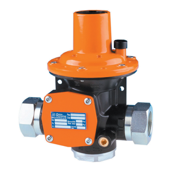
4 - DESCRIPTION AND OPERATION 4.1 - GENERAL DESCRIPTION HP 100 is a single stage balanced plug pressure regulator for gaseous fluids after being purified, suitable for low, medium and high pressure. The main elements of the equipment are: Pos. Description Pos. -
Page 28: Regulator Reaction Modes
4.1.1 - REGULATOR REACTION MODES The HP 100 equipment is a pressure regulator with a “fail open” reaction (on-opening reaction), that is, it opens in the event of: • breakage of main diaphragm; • no regulated pressure signal. 4.2 -... -
Page 29: Intended Use
If no written approval is provided, use shall be considered improper. In the event of “improper use”, PIETRO FIORENTINI S.p.A. shall not be held liable for any damage caused to people or property, and any type of warranty on the equipment shall be deemed void. -
Page 30: Technical Features/Performance
4.4 - TECHNICAL FEATURES/PERFORMANCE The HP 100 equipment is a low, medium and high pressure regulator. The main specifications for this regulator are: Technical features Design pressure (PS) Up to 20 bar Operating temperature range -20 °C - +60 °C Ambient temperature range -20 °C - +60 °C... -
Page 31: Possible Configurations
4.5 - POSSIBLE CONFIGURATIONS The available models of the HP 100 series differ according to the installation of the following accessories: • slam-shut valve; • relief valve; • monitor; • limiter. 4.5.1 - INCORPORATED SLAM-SHUT VALVE The main elements of the model with a built-in slam shut valve are: Pos. -
Page 32: Incorporated Relief Valve
4.5.2 - INCORPORATED RELIEF VALVE The main elements of the model with built-in overflow valve are: Pos. Description Pos. Description Relief valve spring Relief adjustment ring nut Relief vent Tab. 4.18. Fig. 4.4. Incorporated relief valve NOTICE! • The tripping pressure value of the relief valve is lower than the tripping pressure value of the slam-shut valve for maximum downstream pressure. -
Page 33: Monitor
(SG). NOTICE! The HP 100 in monitor configuration (A), only becomes a safety device when installed upstream of another pressure regulator with main control function (B). Compared to the standard version, the controller with monitor function is only equipped with an external impulse socket (C). -
Page 34: Limiteur
(SG). NOTICE! The HP 100 in limiter configuration, only becomes a safety device if the controller with main control func- tion (A) is immovably assembled to the controller with limiteur function (B). The in-line limiteur configuration allows, in the event of a failure of the main regulator (A), to limit the downstream pressure by activating the limiteur regulator (B). -
Page 35: Transport And Handling
5 - TRANSPORT AND HANDLING 5.1 - SPECIFIC WARNINGS FOR TRANSPORT AND HANDLING NOTICE! Transport and handling must be carried out in compliance with the regulations in force in the country of installation by personnel who are: • qualified (specially trained); •... -
Page 36: Packaging And Fasteners Used For Transport
PIETRO FIORENTINI S.p.A.. NOTICE! PIETRO FIORENTINI S.p.A. shall not be liable for any damage to people or property caused by accidents due to failure to comply with the instructions provided in this manual. Tab. 5.22. describes the types of packaging used: Ref. -
Page 37: Packaging Content
5.2 - PACKAGING CONTENT The packaging contains: Description of content HP 100 gas meter including: • regulator; • any seals (if there are swivel fittings); • installation instructions. Tab. 5.21. NOTICE! The use, maintenance and warning manual can be downloaded from the Manufacturer's website: https:// www.fiorentini.com... -
Page 38: Physical Characteristics Hp 100
5.3 - PHYSICAL CHARACTERISTICS HP 100 NOTICE! See the product configurator ('sizing') at PIETRO FIORENTINI S.p.A. (www.fiorentini.com) for equipment dimensions and weights. Fig. 5.7. Physical characteristics HP 100 Overall dimensions Ref. Dimensions [mm] Ø115 Tab. 5.22. Weights [kg] Regulator Regulator + flange DN25... -
Page 39: Physical Characteristics Hp 100/B
5.4 - PHYSICAL CHARACTERISTICS HP 100/B NOTICE! See the product configurator ('sizing') at PIETRO FIORENTINI S.p.A. (www.fiorentini.com) for equipment dimensions and weights. Fig. 5.8. Physical characteristics HP 100/B Overall dimensions Ref. Dimensions [mm] Ø115 Tab. 5.24. Weights [kg] Regulator Regulator + flange DN25... -
Page 40: Equipment Anchoring And Lifting Method
5.5 - EQUIPMENT ANCHORING AND LIFTING METHOD HAZARD! Using lifting equipment (if necessary) for unloading, carrying and handling packages is reserved only for skilled operators who have been properly trained (and are appropriately qualified if required by the regula- tions in force in the country of installation) and are familiar with: •... -
Page 41: Forklift Handling Method
5.5.1 - FORKLIFT HANDLING METHOD HAZARD! It is forbidden to: • Do not transit under suspended loads; • Do not move the load over the personnel operating in the site/plant area. WARNING! The following is not allowed on forklifts: • carrying passengers;... - Page 42 Step Action Image Sollevare lentamente il carico di qualche decina di centimetri e veri carne la stabilità facendo attenzio- Inclinare il montante all’indietro (verso il posto guida) per avvantaggiare il momento ribaltante e Adeguare la velocità d ne che il baricentro del carico sia posizionato al centro delle forche di sollevamento. garantire una maggiore stabilità...
-
Page 43: Packaging Removal
• do not install the equipment; • contact PIETRO FIORENTINI S.p.A. and specify the details provided on the equipment nameplate. WARNING! The single piece of equipment is contained in a specifically created cardboard box. Avoid taking the equipment out of the box before its installation. -
Page 44: Storage And Environmental Conditions
5.7 - STORAGE AND ENVIRONMENTAL CONDITIONS WARNING! Protect the regulator from blows and impacts, even accidental, until it is installed. If the equipment needs to be stored for an extended period, the minimum environmental conditions for the intended stor- age are provided in Tab.5.29. Compliance with these conditions will guarantee the declared performance: Conditions Data Maximum storage period... -
Page 45: Installation
6 - INSTALLATION 6.1 - INSTALLATION PRE-REQUISITES 6.1.1 - ALLOWED ENVIRONMENTAL CONDITIONS WARNING! To safely use the equipment, in full respect of the allowed environmental conditions, follow the data shown on the regulator plate and on any accessories (refer to paragraph 2.8 “Nameplates applied”). WARNING! The regulator must be installed away from atmospheric agents and direct sunlight. -
Page 46: Checks Before Installation
6.1.3 - CHECKS BEFORE INSTALLATION The equipment does not require any further upstream safety device for protection against any overpressure with respect to its PS admissible pressure when, for the upstream reduction station, the maximum incidental downstream pressure MIPd ≤ 1.1 PS MIPd = Maximum incidental downstream pressure value (for further information, see UNI EN 12186:2014). -
Page 47: Specific Safety Instructions For The Installation Step
WARNING! The installer must: • use the fittings and gaskets supplied with the equipment by PIETRO FIORENTINI S.p.A. • fix the swivel joints (when provided) according to the tightening torques specified by standards: NF E29-533: 2014 and NF E29-536: 2017. -
Page 48: General Information On The Line
GENERAL INFORMATION ON THE LINE The device must be installed in the line, with the arrow on its body pointing to the gas flow direction. The usual layout of the regulator HP 100 is as shown in Fig.6.9: Fig. 6.9. In-line placement 6.3.1 - POSSIBLE INSTALLATION POSITIONS... -
Page 49: Installation Procedures
Installation requirements in the presence of Flow direction Installation position: recondensation phenomena NOTICE! Vertical flow In this position, the vents on the regulator allow for the evacuation of condensate. WARNING! Reversed vertical flow If condensation occurs, only the cover can be in- (from bottom to top) stalled by 180°. -
Page 50: Equipment Installation Procedure
Fig. 6.10. Installation diagram NOTICE! The warranty shall be deemed null and void and PIETRO FIORENTINI S.p.A. shall not be held liable for any damage and/or malfunctions if the fittings used during installation are not those supplied. PRESSURE REGULATOR INSTALLATION REV. -
Page 51: Post-Installation Instructions
6.5 - POST-INSTALLATION INSTRUCTIONS WARNING! Ensure that all connections are: • properly connected; • tightened correctly to prevent any leakage during commissioning. WARNING! Protect the regulator from blows and impacts, even accidental. PRESSURE REGULATOR INSTALLATION REV. 00 Use, maintenance and warning manual... -
Page 52: Equipment Adjustments
6.6 - EQUIPMENT ADJUSTMENTS NOTICE! All regulators are calibrated to the values requested by the customer directly at PIETRO FIORENTINI S.p.A. factory No further adjustments are required. The calibration values are specified on the nameplate (refer to paragraph 2.8 “Applied rating plates”). - Page 53 If it is necessary to change the calibration values, proceed as indicated in Tab. 6.34. to increase or decrease the operating pressure: Step Action Necessary equipment Loosen the upper cap (A) of the regulator. Turn the ring nut (B) clockwise •...
- Page 54 PAGE INTENTIONALLY LEFT BLANK PRESSURE REGULATOR INSTALLATION REV. 00 Use, maintenance and warning manual...
-
Page 55: Commissioning/Maintenance Equipment
7 - COMMISSIONING/MAINTENANCE EQUIPMENT 7.1 - LIST OF EQUIPMENT Use of commissioning/maintenance equipment • Name of the user. Operator qualification • Specialised technician. WARNING! The PPE listed in this table is related to the risk associated with the equipment. PPE required For the PPE required to protect against risks associated with the workplace, installation or operating conditions, please refer to: •... - Page 56 PAGE INTENTIONALLY LEFT BLANK PRESSURE REGULATOR REV. 00 COMMISSIONING AND MAINTENANCE EQUIPMENT Use, maintenance and warning manual...
-
Page 57: Commissioning
8 - COMMISSIONING 8.1 - GENERAL WARNINGS 8.1.1 - SAFETY REQUIREMENTS FOR COMMISSIONING HAZARD! During commissioning the risks associated with any discharges to the atmosphere of flammable or nox- ious gases must be evaluated. HAZARD! In case of installation on distribution networks for natural gas, consider the risk associated with explosive mixtures (gas/air) being formed inside the piping, if the line is not subjected to inerting. -
Page 58: Preliminary Procedures For Commissioning
8.3 - CALIBRATION OF SAFETY DEVICES NOTICE! The equipment is regulated at PIETRO FIORENTINI S.p.A. production plants WARNING! Do not tamper with or make any unauthorised changes to the equipment without the approval of PIETRO FIORENTINI S.p.A. -
Page 59: Commissioning Procedure Without Built-In Slam-Shut Valve
8.5 - COMMISSIONING PROCEDURE WITHOUT BUILT-IN SLAM-SHUT VALVE Fig. 8.12. Commissioning of regulator with built-in slam-shut valve To commission the regulator, proceed as described in Tab. 8.38.: Step Action Partially open the pressure relief valve (6) on the outlet pipe. Open the inlet shut-off valve (V1) very slowly. -
Page 60: Start-Up With Built-In Slam-Shut Valve
8.6 - START-UP WITH BUILT-IN SLAM-SHUT VALVE Fig. 8.13. Commissioning of regulator with built-in slam-shut valve After completion of the slam-shut valve tightness test, for commissioning the regulator (A) with in-built slam-shut valve, proceed as shown in Tab. 8.39.: Step Action Make sure that the slam-shut device is in the closed position. - Page 61 Step Action Check that the slam-shut valve remains cocked. Partially open the pressure relief valve (6) on the outlet pipe. Close the pressure relief valve (6) and check the lock up pressure value. Using a foaming agent, check all the joints between shut-off valves (V1 and V2) for proper tightness. Open the downstream shut-off valve (V2) very slowly until the piping has been filled completely.
-
Page 62: Commissioning (With And Without Built-In Slam-Shut Valve) And Monitor
8.7 - COMMISSIONING (WITH AND WITHOUT BUILT-IN SLAM-SHUT VALVE) AND MONITOR NOTICE! For the commissioning procedure of the regulator (A) with monitor (with and without slam-shut valve - B) follow the procedures described in sections 8.6 (for the regulator with slam-shut valve) and 8.5 (for the regulator without slam-shut valve). -
Page 63: Proper Commissioning Check
8.8 - PROPER COMMISSIONING CHECK Check the connections made during the installation of the equipment (refer to chapter 6 “Installation”) for proper sealing through a foaming solution (or equivalent control system). 8.9 - RESET OF SAFETY DEVICES AFTER COMMISSIONING HAZARD! Before resetting the safety devices, eliminate the causes that caused them to trip. - Page 64 PAGE INTENTIONALLY LEFT BLANK PRESSURE REGULATOR COMMISSIONING REV. 00 Use, maintenance and warning manual...
-
Page 65: Maintenance And Functional Checks
WARNING! In case of doubt, do not perform any work. Contact PIETRO FIORENTINI S.p.A. for the necessary clarifica- tions. The management and/or use of the equipment includes interventions that are necessary as a result of normal use such as: •... -
Page 66: Maintenance Operations
Before beginning disassembly of the equipment, make sure that: • the spare parts and parts used in replacements have adequate requirements to ensure the original performance of the equipment. Use recommended original spare parts; • the operator has the necessary equipment (see chapter 7 “Equipment for commissioning/maintenance”). The equipment maintenance operations are divided, from an operational point of view, into two main categories: Commissioning and maintenance operations Routine... -
Page 67: Hp100 Regulator
9.2.2 - HP100 REGULATOR The procedure for disassembling and assembling the regulator, in order to service its internal components, is described in Tab. 9.42.: Step Action Image Disconnect the fittings between the regulator and the downstream pressure sensing point (sensing line), if foreseen. - Page 68 Step Action Image Take out the diaphragm unit (H). Unscrew the lower cap (I). Equipment required to unscrew the lower cap (I): adjustable needle spanner CH50 mm. Take out the shaft (J). WARNING! • INTERNAL RELIEF VALVE ACTIVE: the o-ring must be in the lower groove of the diaphragm shaft.
-
Page 69: Slam-Shut Valve
9.2.3 - SLAM-SHUT VALVE The procedure for disassembling and assembling the slam-shut valve, in order to service its internal components, is de- scribed in Tab. 9.43.: Step Action Image Make sure that the slam-shut device is in the closed position. Unscrew the cap (A) and inner adjustment ring (B) by hand, then pull out the spring assembly (C). - Page 70 Step Action Image Unscrew the lower cap (J). Equipment required to unscrew the lower cap (J): adjustable needle spanner CH50 mm. Remove the spring (K) and the filter (L); Take out the shaft (M). Reassemble the regulator by replacing the diaphragm assembly (Step 6) and shaft (Step 9) by performing the steps described in reverse order.
-
Page 71: Troubleshooting
• qualified and authorised to carry out activities related to the equipment. WARNING! PIETRO FIORENTINI S.p.A. shall not be held liable for any damage to people and property due to services: • other than those described; • performed according to methods other than those specified;... -
Page 72: Operator Qualification Specification
10.2 - OPERATOR QUALIFICATION SPECIFICATION Commissioning • Installer; Operator qualification • User/specialist technician. WARNING! The PPE listed in this table is related to the risk associated with the equipment. PPE required For the PPE required to protect against risks associated with the workplace, installation or operating conditions, please refer to: •... -
Page 73: Troubleshooting Tables
10.4 - TROUBLESHOOTING TABLES NOTICE! Refer to chapter 9 “Maintenance and functional checks” for the pictures of the HP 100 regulator and its accessories. 10.4.1 - TROUBLESHOOTING HP100 REGULATOR Failure Possible causes Intervention Send the regulator to the manufacturer for Valve seat damaged. - Page 74 PAGE INTENTIONALLY LEFT BLANK PRESSURE REGULATOR TROUBLESHOOTING REV. 00 Use, maintenance and warning manual...
-
Page 75: Uninstallation And Disposal
11 - UNINSTALLATION AND DISPOSAL 11.1 - GENERAL SAFETY WARNINGS HAZARD! Make sure that there are no potentially explosive ignition sources in the work area set up to uninstall and/ or dispose of the equipment. WARNING! Before proceeding with uninstallation and disposal, make the equipment safe by disconnecting it from any power supply. -
Page 76: Information Required In Case Of Re-Installation
11.4 - INFORMATION REQUIRED IN CASE OF RE-INSTALLATION NOTICE! Should the equipment be reused after uninstallation, refer to chapters: • “Installation”; • “Commissioning”. 11.5 - DISPOSAL INFORMATION NOTICE! • Proper disposal prevents damage to humans and the environment and promotes the reuse of precious raw materials. -
Page 77: Recommended Spare Parts
If unmarked spare parts are used, PIETRO FIORENTINI S.p.A. their declared performance cannot be guar- anteed. It is recommended to use original spare parts PIETRO FIORENTINI S.p.A. PIETRO FIORENTINI S.p.A. shall not be held liable for any damage caused by using non-original parts. 12.2 - HOW TO REQUEST SPARE PARTS NOTICE! For specific information, please refer to the sales network of PIETRO FIORENTINI S.p.A. - Page 78 PAGE INTENTIONALLY LEFT BLANK PRESSURE REGULATOR RECOMMENDED SPARE PARTS REV. 00 Use, maintenance and warning manual...
-
Page 79: Calibration Tables
SPRING NOTES Description Relief spring code 64470038GI [Pd+(100 - 549)] Relief spring code 64470031RO [Pd+(200 - 399)] Relief spring code 64470038GI [Pd+(400 - 1299)] Tab. 13.51. HP 100 AP Pos. Code Colour Setting field (mbar) 64470135GI YELLOW 300 - 349... -
Page 80: Calibration Tables For Slam-Shut Valve Springs
13.2 - CALIBRATION TABLES FOR SLAM-SHUT VALVE SPRINGS HP 100 Code Colour Setting field (mbar) Maximum pressure triggering 64470116GI YELLOW 450 - 599 64470051BI WHITE 600 - 1299 64470057BL BLUE 1300 - 1999 64470058AR ORANGE 2000 - 3499 64470059AZ SKY BLUE... - Page 81 PAGE INTENTIONALLY LEFT BLANK PRESSURE REGULATOR CALIBRATION TABLES REV. 00 Use, maintenance and warning manual...
Need help?
Do you have a question about the HP 100 and is the answer not in the manual?
Questions and answers