
Related Manuals for Beckhoff EK1914


Summary of Contents for Beckhoff EK1914
- Page 1 AS2000 Operating Manual | EN EK1914 Blindtext Blindtext Blindtext TwinSAFE Bus Coupler with 2 fail-safe inputs and 2 fail-safe outputs 2023-03-01 | Version: 2.0.0...
-
Page 3: Table Of Contents
EtherCAT Terminals........................ 14 E-bus ............................... 15 Power contacts.......................... 15 4 System description TwinSAFE ...................... 16 Extension of the Beckhoff I/O system with safety functions ............ 16 Safety concept .......................... 16 5 Product description .......................... 17 General description ......................... 17 Intended use ........................... 18 Technical data .......................... - Page 4 Address settings on the EK1914 TwinSAFE Bus Coupler .............. 43 Entering a TwinSAFE address and parameters in the System Manager ........ 44 8.3.1 Configuration of the EK1914 for light barriers, light grids, light curtains, etc.... 47 8.3.2 Configuration of the EK1914 for safety switching mats............ 48 9 Diagnosis .............................. 49...
-
Page 5: Notes On The Documentation
Notes on the documentation Disclaimer Beckhoff products are subject to continuous further development. We reserve the right to revise the operating instructions at any time and without prior announcement. No claims for the modification of products that have already been supplied may be made on the basis of the data, diagrams and descriptions in these operating instructions. -
Page 6: Limitation Of Liability
Modifications and changes to the hardware and/or software configuration that go beyond the documented options are prohibited and nullify the liability of Beckhoff Automation GmbH & Co. KG. The following is excluded from the liability: •... -
Page 7: Version Numbers
The original documentation is written in German. All other languages are derived from the German original. Product features Only the product properties specified in the current operating instructions are valid. Further information given on the product pages of the Beckhoff homepage, in emails or in other publications is not authoritative. EK1914 Version: 2.0.0... -
Page 8: Staff Qualification
• Independently identify, avoid and eliminate sources of hazard. • Apply relevant standards and directives. • Implement specifications from accident prevention regulations. • Evaluate, prepare and set up the workplaces. • Evaluate, optimize and execute work independently. Version: 2.0.0 EK1914... -
Page 9: Safety And Instruction
Notes are used for important information on the product. The possible consequences of failure to observe these include: • Malfunctions of the product • Damage to the product • Damage to the environment Information This sign indicates information, tips and notes for dealing with the product or the software. EK1914 Version: 2.0.0... -
Page 10: Beckhoff Support And Service
The employees support you in the programming and commissioning of sophisticated automation systems. Hotline: +49 5246/963-157 E-mail: support@beckhoff.com Web: www.beckhoff.com/support Training Training in Germany takes place in our training center at the Beckhoff headquarters in Verl, at subsidiaries or, by arrangement, at the customer's premises. Hotline: +49 5246/963-5000 E-mail: training@beckhoff.com Web: www.beckhoff.com/training... -
Page 11: For Your Safety
De-energize and switch off components before working on them Check all safety-relevant equipment for functionality before working on the TwinSAFE component. Secure the working environment. Secure the machine or plant against being inadvertently started up. Observe the chapter Decommissioning [} 56]. EK1914 Version: 2.0.0... -
Page 12: The Beckhoff Ethercat Terminal System
The Beckhoff EtherCAT Terminal system The Beckhoff EtherCAT Terminal system The Beckhoff EtherCAT Terminal system is used for decentralized connection of sensors and actuators to a controller. The components of the Beckhoff EtherCAT Terminal system are mainly used in industrial automation and building management systems. -
Page 13: Ethercat Bus Coupler
The Beckhoff EtherCAT Terminal system EtherCAT Bus Coupler Mechanical data Bus Coupler Material polycarbonate, polyamide (PA6.6). Dimensions (W x H x D) 44 mm x 100 mm x 68 mm Mounting on 35 mm mounting rail (EN 60715) with locking Attachable by double slot and key connection Fig. 2: Bus Coupler (EtherCAT) -
Page 14: Ethercat Terminals
The Beckhoff EtherCAT Terminal system EtherCAT Terminals Mechanical data Bus Terminal Material polycarbonate, polyamide (PA6.6). Dimensions (W x H x D) 12 mm x 100 mm x 68 mm or 24 mm x 100 mm x 68 mm Mounting on 35 mm mounting rail (EN 60715) with locking... -
Page 15: E-Bus
The Beckhoff EtherCAT Terminal system E-bus The E-bus is the data path within a terminal strip. The E-bus is led through from the Bus Coupler through all the terminals via six contacts on the terminals' side walls. Power contacts The operating voltage is passed on to following terminals via three power contacts. Terminal strip can be split into galvanically isolated groups by means of potential supply terminals as required. -
Page 16: System Description Twinsafe
Extension of the Beckhoff I/O system with safety functions The TwinSAFE products from Beckhoff enable convenient expansion of the Beckhoff I/O system with safety components, and integration of all the cabling for the safety circuit within the existing fieldbus cable. Safe signals can be mixed with standard signals as required. -
Page 17: Product Description
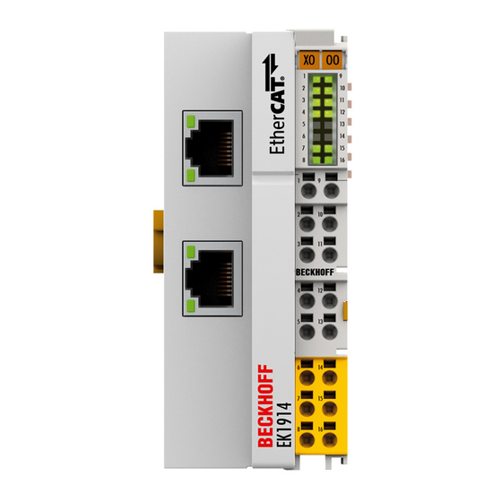
General description EK1914 - TwinSAFE Bus Coupler with two fail-safe inputs and two fail-safe outputs The EK1914 is an EtherCAT Bus Coupler with 4 standard inputs, 4 standard outputs, and 2 fail-safe inputs and 2 fail-safe outputs. The EK1914 fulfils the requirements of DIN EN ISO 13849-1:2008 (Cat 4, PL e). -
Page 18: Intended Use
NOTE Test pulses When selecting actuators, please ensure that the EK1914 test pulses do not lead to actuator switching or a diagnostic message from the EK1914. This module is suitable for operation in an EtherCAT network and can be extended by EtherCAT Terminals of the type ELxxxx. -
Page 19: Technical Data
100BASE-TX Couplers • Transmission medium at least Ethernet CAT-5 cable • Bus connection 2 x RJ45 • Supply voltage for the EK1914 24 V (–15% / +20%) (PELV) • Number of standard inputs • Number of standard outputs • Number of safe inputs •... - Page 20 Between the EtherCAT connections and the channels/E-bus, under common operating conditions • Dimensions (W x H x D) approx. 44 mm x 100 mm x 68 For further information see Dimensions [} 23]. • Weight approx. 123 g Version: 2.0.0 EK1914...
-
Page 21: Safety Parameters
The TwinSAFE Bus Coupler can be used for safety-related applications within the meaning of EN ISO 13849-1 up to PL e (Cat4). To calculate or estimate the MTTFd value out of the PFHD value please refer to the Application Guide TwinSAFE or to the ISO 13849-1:2015 table K.1. EK1914 Version: 2.0.0... -
Page 22: Environmental Conditions
Product description Environmental conditions Beckhoff products are designed for operation under certain environmental conditions, which vary according to the product. The following specifications must be observed for operation and environment in order to achieve the optimum service life of the products as well as to ensure product safety. -
Page 23: Dimensions
Product description Dimensions Fig. 5: Dimensions Width: 44 mm Height: 100 mm Depth: 68 mm EK1914 Version: 2.0.0... -
Page 24: Transport And Storage
You have the option of storing the TwinSAFE component for a short or longer period. Observe the conditions from chapter Environmental conditions [} 22]. Checking the seal for damage Check the barcode sticker used to seal the outer packaging for damage. If the sticker is missing, opened or damaged, contact Beckhoff Support and Service [} 10]. Version: 2.0.0 EK1914... -
Page 25: Installation
The Bus Terminal system is live. Set the Bus Terminal system to a safe, de-energized state before you start mounting, dismounting or wiring the TwinSAFE components. If you work on the TwinSAFE components while the Bus Terminal system is live, you may be injured by electric shock. In addition, the device may be damaged. EK1914 Version: 2.0.0... -
Page 26: Control Cabinet / Terminal Box
Maintain the distances to neighboring devices and control cabinet walls specified in the figure. This is the only way to ensure optimum convection cooling. If sufficient convection cooling is not ensured, the devices may overheat and be damaged. Version: 2.0.0 EK1914... -
Page 27: Installation On Mounting Rails
If you first snap the TwinSAFE terminals onto the mounting rail and then push them next to each other without the tongue and groove interlocking, no functional connection will be established. When correctly mounted, no significant gap should be visible between the housings. EK1914 Version: 2.0.0... -
Page 28: Fig. 8 Removal From Mounting Rail
TwinSAFE terminal is released automatically. 5. Grip the unlocked TwinSAFE terminal simultaneously at the top and bottom of the housing surfaces with thumb and index finger. 6. Pull the TwinSAFE terminal out of the Bus Terminal block with little force. Version: 2.0.0 EK1914... -
Page 29: Electrical Installation
Bus Terminals or digital 4-channel Bus Terminals. Power feed terminals interrupt the power contacts and thus represent the start of a new supply rail. Possible power supply terminals are the EL91xx and the EL92xx. EK1914 Version: 2.0.0... -
Page 30: Overvoltage Protection
TwinSAFE component. 7.4.2 Overvoltage protection Provide a surge filter against overvoltage for the supply voltage of the Bus Terminal block and the TwinSAFE components, if protection against overvoltages is required in your system. Version: 2.0.0 EK1914... -
Page 31: Hd Housing Wiring
Do not turn or move the screwdriver back and forth (do not lever) 2. The wire can now be inserted into the round terminal opening without any force. 3. The terminal closes automatically when the pressure is released, holding the wire safely and permanently. EK1914 Version: 2.0.0... -
Page 32: High Density Terminals
High Density terminals Fig. 11: HD terminals The ELx8xx / KLx8xx series Bus Terminals, like the EK1914 with 16 connection points, are characterized by a particularly compact design, since the packing density on 12 mm is twice that of standard Bus Terminals. -
Page 33: Pin Assignment
The corresponding evaluation takes place in the safety PLC. NOTE Test pulses of the safe outputs When selecting the actuators, ensure that the test pulses of the EK1914 do not lead to switching of the actuator or a diagnostic message of the EK1914. EK1914... -
Page 34: Fig. 13 Cable Length Input
Interference from cables routed in parallel can influence the signal shape of the test pulses and thus cause diagnostic messages. Possible diagnostic messages are, for example, sensor errors. The following illustrations show correct and incorrect signal routing. Observe the illustration legend. Fig. 14: Route signal lines correctly Version: 2.0.0 EK1914... -
Page 35: Fig. 15 Route Signal Lines Incorrectly
400 times per second. In the step mat mode (parameter: "Short cut is no module fault"), test pulses with a typical length of 750 µs are generated in addition to the typical test pulse lengths of 380 µs. EK1914 Version: 2.0.0... -
Page 36: Fig. 16 Cable Length Output
Interference from cables routed in parallel can influence the signal shape of the test pulses and thus cause diagnostic messages. Possible diagnostic messages are, for example, sensor errors. The following illustrations show correct and incorrect signal routing. Observe the illustration legend. Version: 2.0.0 EK1914... -
Page 37: Fig. 17 Route Signal Lines Correctly
The typical length of a test pulse (switching from 24 V to 0 V and back to 24 V) is 300 µs to 800 µs but can also be longer in individual cases. Testing usually takes place 3 to 6 times per second. EK1914 Version: 2.0.0... - Page 38 Installation Test pulses for the outputs The following diagram shows a typical test pulse curve for the two outputs of an EK1914. The parameter Testing of outputs active is enabled. Fig. 19: Test pulses Version: 2.0.0 EK1914...
-
Page 39: Twinsafe Reaction Times
Reaction time of the actuator. This information is typically supplied by the actuator manufacturer WDComm Watchdog time of the communication The following formula results for the typical reaction time: ReactionTime Sensor Input Comm Logic Comm Output Actuator Example for reaction time calculation: ReactionTime EK1914 Version: 2.0.0... -
Page 40: Worst-Case Reaction Time
This error is detected at the output following a safety watchdog time out and leads to a switch- off. This results in the following equation for the worst-case reaction time: ReactionTime Comm Comm Actuator Example for the calculation of the worst-case reaction time: ReactionTime Version: 2.0.0 EK1914... -
Page 41: Tested Devices
Installation Tested devices The following list contains devices that were tested together with the EK1914 TwinSAFE Bus Coupler. The results only apply for the current device hardware version at the time of testing. The tests were carried out in a laboratory environment. Modifications of these products cannot be considered here. If you are unsure, test the hardware together with the TwinSAFE Bus Coupler. -
Page 42: Configuration Of The Ek1914 In Twincat
SystemManager) to the CoE objects set the coupler permanently to the Fail-Stop state. Inserting a Beckhoff TwinSAFE Bus Coupler An EK1914 is inserted in the same way as any other Beckhoff Bus Coupler. In the list, open Safety Terminals and select the EK1914. -
Page 43: Address Settings On The Ek1914 Twinsafe Bus Coupler
Address settings on the EK1914 TwinSAFE Bus Coupler Fig. 21: Address switches The TwinSAFE address of the coupler must be set using the three rotary switches on the side of the EK1914 TwinSAFE Bus Coupler. TwinSAFE addresses between 1 and 4095 are available. Rotary switch... -
Page 44: Entering A Twinsafe Address And Parameters In The System Manager
The TwinSAFE address set using the DIP switch must also be set on the Safe Parameter tab (FSoE Address entry) underneath the EK1914. The parameters for the safe inputs and outputs can also be set here. Fig. 22: Parameters of the EK1914 The parameter settings of the EK1914 can also be set under the respective TwinSAFE connection on the Connection and Safe Parameter tabs. -
Page 45: Fig. 23 Connection Settings
Configuration of the EK1914 in TwinCAT Fig. 23: Connection settings Fig. 24: Parameter settings Parameter overview PrmName Bedeutung Werte FSoE_Address DIP switch address 1 to 4095 Standard outputs In addition the safe output can be switched off from true / false active the standard PLC. - Page 46 Configuration of the EK1914 in TwinCAT PrmName Bedeutung Werte Testing of outputs Test pulses for the outputs are activated true / false active Error acknowledge True: true / false active Bus Coupler errors lead to a reset of the TwinSAFE connection (error code 14 (0x0E)).
-
Page 47: Configuration Of The Ek1914 For Light Barriers, Light Grids, Light Curtains, Etc
EK1914 (see figure)! Fig. 25: Clock outputs Parameter To connect these sensors please set the following parameters for the EK1914 in the TwinCAT System Manager: • Connect the two sensor signals to channels 1 and 2 and activate the entry asynchronous repetition OSSD or any pulse repetition for both the inputs used under the parameter Logic for channel 1 and 2. -
Page 48: Configuration Of The Ek1914 For Safety Switching Mats
The EK1914 also supports the direct connection of safety switching mats. Parameter To connect these safety mats please set the following parameters for the EK1914 in the TwinCAT System Manager: • Connect the two sensor signals to channels 1 and 2 and activate the entry short cut channel x/y is no module fault for both the inputs used under the parameter Logic for channel 1 and 2. -
Page 49: Diagnosis
Diagnosis Diagnosis Diagnosis LEDs The LEDs Diag 1 (LED 7) and Diag 2 (LED 15) display diagnostic information for the EK1914. Fig. 26: Diagnosis LEDs 9.1.1 Diag1 (green) The Diag 1 LED indicates the state of the TwinSAFE interface. The LED is set as soon as the FSoE State... -
Page 50: Diag2 (Red)
Bus Coupler must be checked by Automation GmbH & Co. KG. NOTE Note flashing codes; return the Bus Coupler Note the flashing code displayed and include this information with the Bus Coupler when you return it. Version: 2.0.0 EK1914... -
Page 51: Diagnosis Objects
External supply 0 V output 2, detected with set output External supply 24 V output r 800E:0F Diagnose µC2 Value Description External supply 0 V output 1, detected with set output External supply 24 V output 1 EK1914 Version: 2.0.0... - Page 52 External supply 0 V output 2, detected with set output External supply 24 V output 2 NOTE Differing diagnostic messages possible Due to the variable order or execution of the test series, diagnostic messages differing from those given in the table above are possible. Version: 2.0.0 EK1914...
-
Page 53: Possible Causes Of Diagnostic Messages
Bus Coupler Field potential too high. Voltage on the power Use an R/C or diode-based contacts too high. protective circuit on the actuators EMC faults Take suitable EMC measures Internal defect Exchange Bus Coupler EK1914 Version: 2.0.0... -
Page 54: Service Life
Calendar week: 27 YY: Year of manufacture Year: 2014 SW: Software version Software version: 01 HW: Hardware version Hardware version: 00 In addition the TwinSAFE Bus Couplers bear a unique serial number. Fig. 28: Date Code of EK1914 Version: 2.0.0 EK1914... -
Page 55: Maintenance And Cleaning
Maintenance and cleaning Cleaning by the manufacturer only Do not operate the TwinSAFE component if it is impermissibly dirty according to protection class IP20. Send impermissibly dirty TwinSAFE components to the manufacturer for cleaning. TwinSAFE components are basically maintenance-free. EK1914 Version: 2.0.0... -
Page 56: Decommissioning
In accordance with the WEEE-2012/19/EU directives, you can return used devices and accessories for professional disposal. The transport costs are borne by the sender. Send the used devices with the note "For disposal" to: Beckhoff Automation GmbH & Co. KG Gebäude „Service“ Stahlstraße 31... -
Page 57: Appendix
If there is customer specific data saved on the product, it cannot be ensured that this data might not be restored through for example forensic measures, even after the data is deleted through the provided tool chain. If this data is confidential, the scrapping of the product after usage is recommended to protect this data. EK1914 Version: 2.0.0... -
Page 58: Focus Of Certificates
The current certificates of all TwinSAFE components with the underlying standards and directives can be found at https://www.beckhoff.com/en-en/support/download-finder/certificates-approvals/. If the document refers only to the first four figures of a product (ELxxxx), the certificate is valid for all available variants of the component (ELxxxx-abcd). -
Page 59: Certificate
Appendix 13.3 Certificate Fig. 29: EK1914 EC Declaration of Conformity EK1914 Version: 2.0.0... - Page 60 PE power contact ......................... Fig. 10 Connection of a cable to a terminal point..................Fig. 11 HD terminals ..........................Fig. 12 Pin assignment of the EK1914..................... Fig. 13 Cable length input ........................Fig. 14 Route signal lines correctly ......................Fig. 15 Route signal lines incorrectly .......................
- Page 62 More Information: www.beckhoff.com/EK1914 Beckhoff Automation GmbH & Co. KG Hülshorstweg 20 33415 Verl Germany Phone: +49 5246 9630 info@beckhoff.com www.beckhoff.com...
Need help?
Do you have a question about the EK1914 and is the answer not in the manual?
Questions and answers