Table of Contents
Advertisement
Quick Links
Advertisement
Table of Contents

Related Manuals for Atest Gaz SmArtGas 4


Summary of Contents for Atest Gaz SmArtGas 4
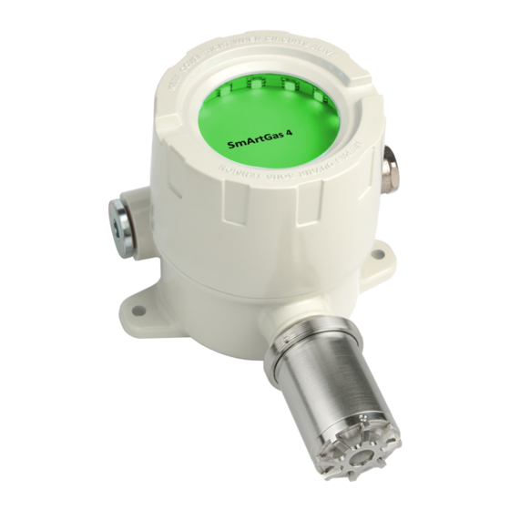
- Page 1 User Manual Gas Detector SmArtGas 4 Product code: PW-044-SG4-X POD-061-ENG R12...
- Page 2 We design, manufacture, implement and support: Systems for Monitoring, Detection and Reduction of gas hazards We invite you to familiarize yourself with our offer on www.atestgaz.pl Atest Gaz A. M. Pachole sp. j. ul. Spokojna 3, 44-109 Gliwice Poland tel.: +48 32 238 87 94 fax: +48 32 234 92 71 e-mail: contact@atestgaz.pl...
-
Page 3: Table 1: Optical Indicators Status Notation
www.atestgaz.pl Remarks and reservations Read and understand this manual prior to connection and operation of the device. Keep the User Manual with the device for future reference. The manufacturer shall not be held responsible for any errors, damage or defects caused by improper selection of suitable devices or cables, errors in installation of equipment or any misuse due to failure to understand the document content. -
Page 4: Table Of Contents
www.atestgaz.pl Table of contents 1 Preliminary information........................6 1.1 Functional properties..........................6 1.2 Marking of explosion protection......................7 1.3 Additional information related to the explosion-proof protection of the device........7 1.4 Cable glands and blanking plugs......................8 1.5 Cables..............................8 1.6 Blanking enclosure..........................8 1.7 The principle of operation........................8 1.8 Gas detector status..........................8 1.9 Detected gases............................9 1.10 Output signal............................9... - Page 5 www.atestgaz.pl List of Tables Table 1: Optical indicators status notation....................3 Table 2: Meaning of information provided on the rating plate..............7 Table 3: Gas detector status........................9 Table 4: Connections diagram for the option with the RS-485 port............12 Table 5: Connections diagram for the option with Teta Bus port..............13 Table 6: Constant output signals......................14 Table 7: Intervals of the output current according to the detector status..........14 Table 8: Operation modes of gas detectors with the Bluetooth interface..........15...
-
Page 6: Preliminary Information
Preliminary information The SmArtGas 4 gas detector is a device designed as a components of the Gas Safety System dedicated for operation in areas with potentially explosive atmospheres and under heavy-duty industrial conditions with broad range of ambient parameters variations (high temperatures, corrosive gases, moisture and dust). The key feature of the device, indispensable to guarantee safe and unproblematic operation is its conformity to requirements of the ATEX EU Directive and IECEx standards. -
Page 7: Marking Of Explosion Protection
www.atestgaz.pl Basic functionalities Non-invasive calibration and configuration – the gas detector can be calibrated and parametrized (e.g. the alarm thresholds) in hazardous areas without opening the housing or turning off other parts of the gas safety system (only for RS-485). Ability to calibrate gas detectors mounted at inaccessible locations. -
Page 8: Cable Glands And Blanking Plugs
www.atestgaz.pl Cable glands and blanking plugs The cable gland and blanking plug are replaceable elements. To select spare ones please obey the following rules: ATEX and IECEx certificates, degree of explosion protection (Ex code) – no worse than the detector (see Table 11), operating temperature range (see Table 11), appropriate mounting thread –... -
Page 9: Detected Gases
www.atestgaz.pl Mode Description Lock Gas concentration is above the overload value (the default value is 100% LEL). The detector is locked (see Appendix [3]) – the last value of the concentration is shut. The detector does not make measurements. It is possible to unlock the condition by means of sending the applicable command from the control unit or from the superior system. -
Page 10: Safety
www.atestgaz.pl The calibration procedure is described in Section 6.6.2.2. In addition, the calibration procedure for gas detectors furnished with the FL.C head must be carried out with consideration of the following constraints: flow rate of a reference gas must be not less than 0.5 ltr./min, wind velocity nearby the detector must not exceed 0.5 m/s. -
Page 11: Conditions Of The Working Environment
www.atestgaz.pl Despite the power supply voltage for the Gas Safety System is off, dangerous voltage may persist across terminals of the control unit. Such a voltage may come from another system controlled by the same unit, for instance ventilation, that use one output pin of the control unit. -
Page 12: Input-Output Interfaces
www.atestgaz.pl ~205 Figure 5: The construction of the gas detector – version with acoustic – and its dimensions Input-output interfaces Electric interface Assignment of contacts on the terminal block depends on the device configuration (see details is Section 10). All possible options of the terminal block layouts are shown on illustrations below. 4.1.1 RS-485 digital communication port Figure 6: Electric connections for the option with the RS-485 port... -
Page 13: Rs-485
www.atestgaz.pl 4.1.2 Teta Bus digital communication port Figure 7: Electric connections for the option with the Teta Bus port Port designation Name Description TETA BUS -, + Combined transmission and power supply lines 4-20 4 – 20 mA current output R1.1 –... -
Page 14: Relay Outputs
www.atestgaz.pl Maximum limits for U and R are provided in Table 11. More configuration details – see Section 6.4.1. 4.3.2 Operation modes – status details The level of output current is in proportion to the gas concentration measured by the detector (constant output signal). -
Page 15: Table 8: Operation Modes Of Gas Detectors With The Bluetooth Interface
www.atestgaz.pl The the Bluetooth interface behaviour depends on the operation mode selected for the Bluetooth port upon configuration and position of the magnetic key. See details in Table 8 below. The detector is seen on The detector can Magnetic key in Operation of the Bluetooth interface the list of devices with communicate via the... -
Page 16: User Interface
www.atestgaz.pl Permament magnet Figure 10: Gas detector with a permanent magnet in place Upon communication between the gas detector and the control software is established, the magnetic key/permanent magnet can be removed. User interface A detailed description of the user interface is provided in the Attachment [5]. Life cycle Transportation The device can be shipped in the same way as new equipment of that type. -
Page 17: Figure 11: Grounding Connection And Correct Cable Laying
www.atestgaz.pl 6.2.3 Electric network The applied flameproof cable glands allows to introduce cables with diameters of a specific range. The suggested cable types are included in the Guide – "Sigma Gas Safety System" (POD-070-ENG). When performing electrical connections, it is necessary to observe the following order: make sure that the connected cables are disconnected from any electrical circuits and potentials, make sure that during installation there is no risk of explosion or fire, unlock the detector cover by loosening the cover locking screw which is located on the periphery,... -
Page 18: Commissioning
www.atestgaz.pl The cable shield shall be isolated and slightly protrude from the cable entry inside the detector. The shield cannot be connected to any device point. A detailed description of the preparation of the cable and connecting the cable to the detector is provided in Appendix [6]. -
Page 19: Configuration Of Gas Detectors
www.atestgaz.pl The detector behaviour after power on is described in Table 3. If a test of the gas detection system is required, supply test gas to the gas detector and make sure that the detector behaviour is in line with the specification. It is recommended that –... -
Page 20: Troubleshooting
www.atestgaz.pl Setting of jumpers Operation mode SOURCE of electric current (default setting) SINK for electric current Table 9: Configuration of the embedded source of electric current 6.4.2 End-line terminals The communication port is furnished with end-line terminals. Configuration of these terminals needs opening of the device housing to insert a jumper into the terminal connector (TERM.). - Page 21 Gas detectors manufactured by Atest Gaz are classified to the A category of instruments (see Appendix [7]) with respect to environments conditions for calibration.
- Page 22 www.atestgaz.pl During calibration the following is determined: the degree of characteristics drift, the degree of sinter contamination (measuring the response time T90), the degree of sensor wear, The calibration also includes checks of the following explosion proof properties: tightness of cables in cable glands, retighten glands when necessary, symptoms of a flameproof housing damage.
-
Page 23: Figure 13: Design Of The Gas Sensing Head
www.atestgaz.pl Cover with the sinter Oring Ring Protective cover Membrane (hydrophobic side) Securing bolt Figure 13: Design of the gas sensing head Inner side, not hydrophobic. Outer side, hydrophobic. Clearly visible, shiny fibers. Matte surface, smoother than printer The surface is more porous than paper. -
Page 24: Utilization
Gas detectors SmArtGas 4 are designed for operation in areas with potentially explosive atmospheres. Thus, its explosion-proof properties must be verified and maintained on regular basis in the following way: checking and cleaning inserts made of sintered material (dry cleaning with a brush or a cloth), checking of the cable gland with verification of its sound installation and lack of damage. -
Page 25: Technical Specification
www.atestgaz.pl Technical specification Power supply • Voltage V 15 – 50 V • Power 0,1 – 4 W (depends on the configuration, see Table 12) Environment In operation Storage • Ambient temperatures Ta Specified depending on: 0 – 40 • the temperature class of the device (see line ATEX and IECEx below), •... -
Page 26: Table 11: Technical Specification
www.atestgaz.pl • IP66/IP67 (measuring head with membrane FL.M, FH.M) • IP63 (other) Analog output 4 – 20 mA • Output type Sink / source • R (source mode) 300 Ω load_MAX • U (sink mode) 30 V (max. voltage between pins „S” and „-”) S_MAX Digital output parameters •... -
Page 27: List Of Consumables
List of consumables Consumables Lifetime Manufacturer Product code Breathing flameproof enclosure with an insert Depends on ambient Atest Gaz PWS-046-A made of sintered material, size 5 mm conditions Breathing flameproof enclosure with an insert Depends on ambient Atest Gaz PWS-055-A made of sintered material, size 2.5 mm... -
Page 28: List Of Accessories
www.atestgaz.pl List of accessories Product code Description PW-063-A Ventilation Adapter AW1 PW-064-WM4 Mounting Bracket WM4 PW-064-WM6 Mounting Bracket WM6 PW-064-WM11 Mounting Bracket WM11 PW-069-DP2 Roofing for the WM6 bracket PW-082-X Calibration kit PW-049-CB6 Service cable CB6 EM-183-A Blanking Enclosure PW-125-KEY1 Magnetic Key KEY1 (for PW-044-SG4-X, PW-093-RA4-X-ALB/ALZ/C/SS-X gas detectors) PW-126-A... -
Page 29: Product Code
Product code SmArtGas 4 Gas Detector PW-044-SG4- AI WI MC Selected by the manufacturer depending on the chosen – field value does not matter Converter module when ordering the product (when ordering, please specify X, available EC, PEL, IR, PID options show the used sensor type –... -
Page 30: Appendices
Appendices DEZG136-ENG – EC Declaration of Conformity – SmArtGas 4 PU-Z-114-ENG – SmArtGas 4, ProGas 4 – special design PU-Z-093-ENG – Instructions for removing the lock of a detector with a catalytic sensor PU-Z-113-ENG – Register map of gas detectors of PW-017, PW-044 and PW-093 type PU-Z-073-ENG –... - Page 31 EU Declaration of Conformity Atest Gaz A. M. Pachole sp. j. declares with full responsibility, that the product: (Product description) (Trade name) (Type identifier or Product code) Gas Detector SmArtGas 4 PW-044 complies with the following Directives and Standards: in relation to Directive 2014/34/EU –...
- Page 32 PW-017 PG4.LV FL, FL.M, FL.C, HL, HR FL, FL.C, FL.M, FH, FH.M, HL, HH, HW FH, FH.M, HH Atest Gaz A. M. Pachole sp. j. tel.: +48 32 238 87 94 p. 1/2 Appendix: PU-Z-114-ENG R05 ul. Spokojna 3, 44-109 Gliwice, Poland fax: +48 32 234 92 71 VAT No.: PL 9691433231...
- Page 33 Catalytic sensor, hydrogen, 40% LEL (Ta: -20 – 50°C) Nickel plated brass, clamping range 7 – 13 mm. See details in POD-066-ENG Cable gland STD.NB03 „Cable glands used in gas detectors produced by Atest Gaz” Atest Gaz A. M. Pachole sp. j. tel.: +48 32 238 87 94 p.
- Page 34 Detectors using a catalytic sensor (more details concerning the sensor – see User Manual POD-062-ENG “Sensors used in gas detectors produced by Atest Gaz”) are equipped with a system protecting against its damage caused by a gas concentration exceeding the measuring range of the sensor and before entering non-monotonic part of the catalytic sensor characteristics.
- Page 35 Test Test mode Warm_Up Sensor warm-up 11..15 Inessential data, can take any value Atest Gaz A. M. Pachole sp. j. tel.: +48 32 238 87 94 p. 1/1 Appendix: PU-Z-113-ENG R01 ul. Spokojna 3, 44-109 Gliwice, Poland fax: +48 32 234 92 71 VAT No.: PL 9691433231...
- Page 36 – red Gas overload The display has light-sensitive area, which ensures appropriate backlit of the display during operation in an unlit room. Atest Gaz A. M. Pachole sp. j. tel.: +48 32 238 87 94 p. 1/5 Appendix: PU-Z-073-ENG R05 ul.
- Page 37 The display shows LOCK information. Display description contains sample content. The state occurs only in case of detectors with a catalytic sensor. The lock mechanism is active. Atest Gaz A. M. Pachole sp. j. tel.: +48 32 238 87 94 p.
- Page 38 0,0 ppm turned off. AWK2100H The display shows AWK2100H message. Atest Gaz A. M. Pachole sp. j. tel.: +48 32 238 87 94 p. 3/5 Appendix: PU-Z-073-ENG R05 ul. Spokojna 3, 44-109 Gliwice, Poland fax: +48 32 234 92 71 VAT No.: PL 9691433231...
- Page 39 Description Sensor lock – sensor off, the last measurement latched Atest Gaz A. M. Pachole sp. j. tel.: +48 32 238 87 94 p. 4/5 Appendix: PU-Z-073-ENG R05 ul. Spokojna 3, 44-109 Gliwice, Poland fax: +48 32 234 92 71 VAT No.: PL 9691433231...
- Page 40 Bluetooth module is failure bit 13 calibration time is exceeded bit 14 digital amplifier operation monitor warning Atest Gaz A. M. Pachole sp. j. tel.: +48 32 238 87 94 p. 5/5 Appendix: PU-Z-073-ENG R05 ul. Spokojna 3, 44-109 Gliwice, Poland fax: +48 32 234 92 71 VAT No.: PL 9691433231...
- Page 41 For the systems with RS-485 interface, it is necessary to make sure that A and B transmission signals as well as + and – power supply were led with the use of the cables which belong to one pair. Atest Gaz A. M. Pachole sp. j. tel.: +48 32 238 87 94 p.
- Page 42 It is unacceptable to leave a reserve inside the detector. Atest Gaz A. M. Pachole sp. j. tel.: +48 32 238 87 94 p.
- Page 43 www.atestgaz.pl Classification of chemicals used at Atest-Gaz Because of the need to present a consistent and high level of maintenance services, to ensure the safety of the calibration process and to create a basis for a rational calculation of the costs of this process, Atest-Gaz developed the "Classification of Chemical Substances"...
- Page 44 www.atestgaz.pl Category Description Terms of facility calibration No precipitations, no strong winds, Cylinder gases, temperature over – 10 C¹. stable environment In other cases, calibration at a location that meets the above conditions (necessary to remove the detectors). No precipitations, no strong winds, Cylinder gases, temperature over + 10...
- Page 45 www.atestgaz.pl Notes...
- Page 46 www.atestgaz.pl Notes...
- Page 48 Atest Gaz A. M. Pachole sp. j. Spokojna 3, 44-109 Gliwice tel.: +48 32 238 87 94 fax: +48 32 234 92 71 e-mail: contact@atestgaz.pl For more details on our devices and other products and services offered by us, visit:...
Need help?
Do you have a question about the SmArtGas 4 and is the answer not in the manual?
Questions and answers