Table of Contents
Advertisement
Quick Links
Advertisement
Table of Contents

Related Manuals for ADJ ENCORE PROFILE MINI COLOR


Summary of Contents for ADJ ENCORE PROFILE MINI COLOR
- Page 1 ENCORE PROFILE MINI COLOR User Manual...
- Page 2 ©2023 ADJ Products, LLC all rights reserved. Information, specifications, diagrams, images, and instructions herein are subject to change without notice. ADJ Products, LLC logo and identifying prod- uct names and numbers herein are trademarks of ADJ Products, LLC. Copyright protection claimed includes all forms and matters of copyrightable materials and information now allowed by statutory or judicial law or hereinafter granted.
-
Page 3: Table Of Contents
T A B L E O F C O N T E N T S Introduction Limited Warranty (USA Only) Warranty Registration | Features Safety Guidelines Overview Installation Accessory Installation Gobo Operation Remote Device Management (RDM) Control Panel System Menu DMX Setup DMX Traits Dim Modes... -
Page 4: Introduction
I N T R O D U C T I O N Unpacking: Thank you for purchasing the Encore Profile Mini Color by ADJ Products, LLC. Every unit has been thoroughly tested and has been shipped in perfect operating condition. Carefully check the shipping carton for damage that may have occurred during shipping. -
Page 5: Limited Warranty (Usa Only)
The sole responsibility of ADJ Products, LLC under this warranty shall be limited to the repair of the product, or replacement thereof, including parts, at the sole discretion of ADJ Products, LLC. All products covered by this warranty were manufactured after August 15, 2012, and bear identifying marks to that effect. -
Page 6: Warranty Registration | Features
F E A T U R E S The ADJ Encore Profile Mini Color is a feature-packed ellipsoidal that is ideal for applications where space is at a premium. It features an LED engine comprised of 16 x 3.5W RGBWAL (red / green / blue / white / amber / lime) LEDs, which offers an output of 300 Lumens and a CRI of >86. -
Page 7: Safety Guidelines
THIS FIXTURE IS COMPOSED OF SOPHISTICATED ELECTRONIC COMPONENTS. TO GUARANTEE SMOOTH OPERATION, IT IS IMPORTANT TO FOLLOW ALL INSTRUCTIONS AND GUIDELINES IN THIS MANUAL. ADJ PRODUCTS, LLC IS NOT RESPONSIBLE FOR INJURY AND/OR DAMAGES RESULTING FROM THE MISUSE OF THIS FIXTURE DUE TO THE DISREGARD OF THE INFORMATION PRINTED IN THIS MANUAL. -
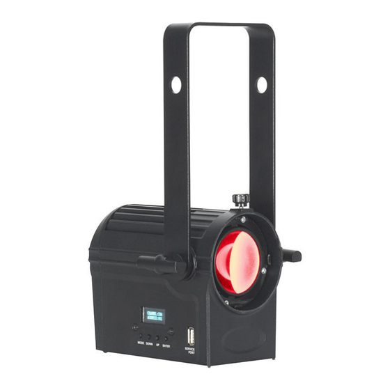
Page 8: Overview
O V E R V I E W Mounting Yoke Barrel Installation Thumb Screw Yoke Adjustment Knob Display Screen Service Port Mode Down Enter Button Button Button Button Power Power... -
Page 9: Installation
I N S T A L L A T I O N FLAMMABLE MATERIAL WARNING Keep fixture minimum 5.0 feet (1.5m) away from flammable materials and/or pyrotechnics. ELECTRICAL CONNECTIONS A qualified electrician should be used for all electrical connections and/or installations. USE CAUTION WHEN POWER LINKING FIXTURES OF OTHER MODEL TYPES, AS THE POWER CONSUMPTION OF OTHER MODEL FIXTURES MAY EXCEED THE MAX POWER OUTPUT ON THIS FIXTURE. - Page 10 I N S T A L L A T I O N CLAMP INSTALLATION This fixture features a mounting point on the yoke for the attachment of a mounting clamp. There is also a safety cable loop located on the rear of the fixture above the DMX ports (see the illustration below).
- Page 11 I N S T A L L A T I O N STAND MOUNTING This unit can also be installed atop a tripod stand. Simply insert the threaded bolt on the top of the tripod stand through the hole in the mounting yoke. Tighten the nut onto the threaded bolt to secure the mounted device in place.
- Page 12 LEDs. This issue is not unique to ADJ lighting fixtures; it is a common issue with lighting fixtures from all manufacturers. Although there is no true way to fully prevent this issue from happening, the guide- lines below can reduce the risk of any potential damage if followed.
-
Page 13: Accessory Installation
A C C E S S O R Y I N S T A L L A T I O N BARREL To install the barrel, remove the thumbscrew located at the top of the fixture’s lens frame, then insert the back end of the barrel (the side closest to the gobo holder) into the lens frame, making sure that the hole on the barrel is aligned with the thumbscrew hole on the lens frame (Fig. - Page 14 A C C E S S O R Y I N S T A L L A T I O N BARNDOORS To install the barndoors, press the release on the retainer clip at the end of the barrel, and flip the clip open (Fig.
-
Page 15: Gobo
G O B O Image GOBO DIMENSIONS Diameter Outer Image Gobo Type Thickness Diameter Diameter Outer 1.772 in 1.220 in 0.008 in Diameter Metal (45mm) (31mm) (0.2mm) 1.555 in 1.220 in 0.039 in Glass Thickness (39.5mm) (31mm) (1mm) GOBO HOLDER DIMENSIONS 0.063in (1.6mm) 1.874in... - Page 16 G O B O INSTALLATION Remove the screw from the gobo holder, and open up the two halves of the gobo holder (Fig. 1). Please note that the half of the gobo holder with the raised surface is the front, while the half with the flat surface and the handle is the back.
-
Page 17: Operation
O P E R A T I O N ZOOM FUNCTION The zoom function on this fixture is adjusted manually using a sliding knob located on the side of the barrel, as shown in the illustration below. Push the sliding knob towards the front of the barrel to zoom out, or backwards to zoom in. -
Page 18: Remote Device Management (Rdm)
R E M O T E D E V I C E M A N A G E M E N T ( R D M ) NOTE: In order for RDM to work properly, RDM enabled equipment must be used throughout the entire system, including DMX data splitters and wireless systems. -
Page 19: Control Panel
System Menu by navigating to PERSONALITY > DISPLAY > AUTO LOCK. To unlock the display screen controls, simply press and hold the Mode button until the controls unlock. SOFTWARE PORT / SOFTWARE UPDATES Please contact ADJ customer support for the latest software and updating instructions. -
Page 20: System Menu
S Y S T E M M E N U Set DMX address of the 001 - 511 Address unit. Select DMX channel Channel mode Mode 13Ch 14Ch DMX SETTINGS 16Ch If DMX signal is lost, Hold unit holds last settings If DMX signal is lost, Blackout unit takes all channels... - Page 21 S Y S T E M M E N U Green Blue Individual color calibra- tion White Amber Lime Red2 Green2 Service PERSONALITY Blue2 CCT white balance Passcode = (continued) calibration White2 Amber2 Lime2 Select whether to power up service port in On / Off USB Update preparation for software...
- Page 22 S Y S T E M M E N U Current fixture tempera- Current xxx F / xxx C ture Fixture Max fixture temperature Max Resettable xxx F / xxx C Temp since last reset INFORMATION (continued) Last Max Temp Reset Max Resettable Passcode = 038 Reset...
-
Page 23: Dmx Setup
2 and 3 of a male XLR connector (DATA + and DATA -). This unit is inserted in the female XLR connector of the last unit in your daisy chain to terminate the line. Using a cable terminator (ADJ part number Z-DMX/T) will decrease the chances of erratic behavior. - Page 24 D M X S E T U P DMX ADDRESSING All fixtures should be given a DMX starting address when operating with a DMX controller, in order to ensure that the correct fixture responds to the correct control signal. This digital starting address is the channel number from which the fixture starts to “listen”...
-
Page 25: Dmx Traits
D M X T R A I T S CHANNEL DMX VALUE FUNCTION 2CH 4CH 5CH 6CH 13CH 14CH 16CH 000 - 255 Red, 0% to 100% Green, 0% to 100% 000 - 255 Blue, 0% to 100% 000 - 255 White, 0% to 100% 000 - 255 Amber, 0% to 100%... - Page 26 D M X T R A I T S CHANNEL DMX VALUE FUNCTION 2CH 4CH 5CH 6CH 13CH 14CH 16CH Dimming Speed 0.1s 0.2s 0.3s 0.4s 0.5s 0.6s 0.7s 0.8s 0.9s 1.0s 1.5s 2.0s 3.0s 4.0s 5.0s 6.0s 7.0s 8.0s 9.0s 10.0s 161 - 255...
- Page 27 D M X T R A I T S CHANNEL DMX VALUE FUNCTION 2CH 4CH 5CH 6CH 13CH 14CH 16CH LED Refresh Rates (continued) 1010 Hz 1020 Hz 1030 Hz 1040 Hz 1050 Hz 1060 Hz 1070 Hz 1080 Hz 1090 Hz 1100 Hz 1110 Hz...
- Page 28 D M X T R A I T S CHANNEL DMX VALUE FUNCTION 2CH 4CH 5CH 6CH 13CH 14CH 16CH LED Refresh Rates (continued) 1420 Hz 1430 Hz 1440 Hz 1450 Hz 1460 Hz 1470 Hz 1480 Hz 1490 Hz 1500 Hz 2500 Hz 4000 Hz...
-
Page 29: Dim Modes
D I M M O D E S DIMMER 100% Time (ms) 0 Sec Rise Time Down Time 0 sec Fade Time 1 sec Fade Time Dimming Curve Ramp Effect Rise Time (ms) Down Time (ms) Rise Time (ms) Down Time (ms) Standard (default) Stage 1100... -
Page 30: Color Macros Chart
C O L O R M A C R O S C H A R T COLOR COLOR GREEN BLUE GREEN BLUE MACRO VALUE MACRO VALUE 165 - 168 001 - 004 169 - 172 005 - 008 173 - 176 009 - 012 177 - 180 013 - 016... -
Page 31: Daisy Chain Power Linking | Cleaning & Maintenance
Regular inspections are recommended to ensure proper function and extended life. There are no user serviceable parts inside this fixture. Please refer all other service issues to an authorized ADJ service technician. Should you need any spare parts, please order genuine parts from your local ADJ dealer. -
Page 32: Dimensional Drawing
D I M E N S I O N A L D R A W I N G S FIXTURE ONLY 6.260in (159mm) 8.819in (224mm) 5.669in (144mm) - Page 33 D I M E N S I O N A L D R A W I N G S 15-30 LENS INSTALLED 8.760in (222.5mm) 6.024in (153mm)
- Page 34 D I M E N S I O N A L D R A W I N G S 25-50 LENS INSTALLED 6.988in (177.5mm) 6.024in (153mm)
-
Page 35: Specifications
S P E C I F I C A T I O N S SOURCE • 16x3.5W RGBWAL (Red/Green/Blue/White/Amber/Lime) LED Engine • 50,000 Hour Average LED Life* • *LED Life may vary depending on several factors including but not limited to: Environmental Conditions, Power/Voltage, Usage Patterns (On-Off Cycling), Control, and Dimming. -
Page 36: Error Codes | Accessory Information
E R R O R C O D E S CODE DESCRIPTION LED Temp LED Temperature Error A C C E S S O R Y I N F O R M A T I O N SKU NUMBER DESCRIPTION EP Mini Lens 1530 15- to 30-degree Manual Zoom Lens EP Mini Lens 2550... - Page 37 This page intentionally left blank.
Need help?
Do you have a question about the ENCORE PROFILE MINI COLOR and is the answer not in the manual?
Questions and answers