Table of Contents
Advertisement
Quick Links
Advertisement
Table of Contents

Related Manuals for ADJ ENCORE BURST 200


Summary of Contents for ADJ ENCORE BURST 200
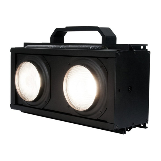
- Page 1 ENCORE BURST 200 User Manual...
- Page 2 Products, LLC brands and product names are trademarks or registered trademarks of their respective companies. ADJ Products, LLC and all affiliated companies hereby disclaim any and all liabilities for property, equipment, building, and electrical damages, injuries to any persons, and direct or indirect economic...
-
Page 3: Table Of Contents
TABLE OF CONTENTS General Information Limited Warranty (USA Only) Safety Guidelines Maintenance Guidelines Fixture Overview Installation Instructions System Menu Dimming Curve DMX Channel Functions and Values Specifications | FCC Statement Dimensional Drawings... -
Page 4: General Information
Please do NOT discard the outer shipping carton in the trash. Please recycle whenever possible. CUSTOMER SUPPORT: Contact ADJ Service for any product related service and support needs. Also forums.adj.com visit with questions, comments or suggestions. -
Page 5: Limited Warranty (Usa Only)
LIMITED WARRANTY (USA ONLY) A. ADJ Products, LLC hereby warrants, to the original purchaser, ADJ Products, LLC products to be free of manufacturing defects in material and workmanship for a prescribed period from the date of purchase (see specific warranty periods below). This warranty shall be valid only if the product is purchased within the United States of America, including possessions and territories. -
Page 6: Safety Guidelines
This fixture is a sophisticated piece of electronic equipment. To guarantee smooth operation, it is important to follow all instructions and guidelines in this manual. ADJ is not responsible for injury and/ or damages resulting from the misuse of this fixture due to the disregard of the information printed in this manual. - Page 7 SAFETY GUIDELINES • DO NOT TOUCH the fixture housing during operation. • Turn OFF the power and allow approximately 15 minutes for the fixture to cool down before serv- ing. • DO NOT shake fixture, avoid brute force when installing and/or operating fixture. • DO NOT operate fixture if the power cord is frayed, crimped, damaged and/or if any of the power cord connectors are damaged and do not insert into the fixture securely with ease.
-
Page 8: Maintenance Guidelines
MAINTENANCE GUIDELINES DISCONNECT POWER BEFORE PERFORMING ANY MAINTENANCE! CLEANING Frequent cleaning is recommended to insure proper function, optimized light output, and an extended life. The frequency of cleaning depends on the environment in which the fixture operates: damp, smoky, or particularly dirty environments can cause greater accumulation of dirt on the fixture’s optics. Clean the external lens surface regularly with a soft cloth to avoid dirt/debris accumulation. -
Page 9: Fixture Overview
FIXTURE OVERVIEW INCLUDED ITEMS • Omega Bracket • Yoke Bracket Kit • Power Cable... -
Page 10: Installation Instructions
INSTALLATION INSTRUCTIONS IPX4 RATED An IP rated lighting fixture is commonly installed in outdoor environments and has been designed with an enclosure that effectively protects the ingress (entry) of external foreign objects such as dust and water. The International Protection (IP) rating system is commonly expressed as “IP” (Ingress Protection) followed by two numbers (i.e. - Page 11 INSTALLATION INSTRUCTIONS DO NOT INSTALL THE FIXTURE IF YOU ARE NOT QUALIFIED TO DO SO! Fixture MUST be installed following all local, national, and country commercial electrical and con- struction codes and regulations. Before rigging/mounting a single fixture or multiple interconnected fixtures to any metal truss/struc- ture or placing the fixture(s) on any surface, a professional equipment installer MUST be consulted to determine if the metal truss/structure or surface is properly certified to safely hold the combined weight of the fixture(s), clamps, cables, and accessories.
- Page 12 INSTALLATION INSTRUCTIONS OVERHEAD RIGGING Overhead rigging requires extensive experience, including calculating working load limits, installation material being used, and periodic safety inspection of all installation material and the fixture, among other skills. If you lack these qualifications, DO NOT attempt the installation yourself. Improper installation can result in bodily injury and property damage.
- Page 13 INSTALLATION INSTRUCTIONS YOKE BRACKET KIT The included Yoke Bracket Kit can be attached to the fixture using the included hardware. Follow the installation steps below. YOKE BRACKET FOR SINGLE FIXTURE INSTALLATION ONLY! DO NOT USE WHEN CONNECTING MULTIPLE FIXTURES TOGETHER! 1.
- Page 14 INSTALLATION INSTRUCTIONS CONNECTING FIXTURES TOGETHER The fixture includes a unique interlocking system which allows multiple fixtures to be connected together horizontally, using the 4 included spring-loaded interlocking pins on each fixture. Follow the installation steps below. OMEGA BRACKET MUST BE USED WHEN CONNECTING FIXTURES TOGETHER! 1.
- Page 15 INSTALLATION INSTRUCTIONS MAXIMUM NUMBER OF CONNECTING FIXTURES = 10 Each set of 10 fixtures must be attached to a structure which can support 10x the total weight of the entire assembly (10 x combined weight of 10 fixtures and any associated hardware and accesso- ries).
- Page 16 INSTALLATION INSTRUCTIONS SAFETY CABLES Each fixture includes a Safety Cable attachment loop on the back. All fixtures installed in an over- head configuration MUST always be secured with a dedicated secondary safety attachment, such as an appropriately rated safety cable that can hold 10 times the weight of the fixture. WHEN INSTALLING THE FIXTURE IN A SUSPENDED ENVIRONMENT, ALWAYS ATTACH AN INDEPENDENT SAFETY CABLE BETWEEN THE TRUSS/STRUC- TURE AND THE FIXTURE IN ORDER TO ENSURE THAT THE FIXUTRE WILL NOT...
- Page 17 INSTALLATION INSTRUCTIONS ADJUSTING LED LENS POSITION DEGREE The LED lens position can easily be adjusted manually from the default 0-degree position, to 7.5+ or 15+ degrees (UP) and -7.5 and -15.0 degrees (DOWN). Simply push the LED lens array either UP or DOWN by hand until the desired angle is achieved.
-
Page 18: System Menu
SYSTEM MENU The fixture includes an easy to navigate system menu where fixture settings can be adjusted via the LCD control panel located on the back of the fixture. (see image below) To access the system menu press and hold the MENU button for 3 seconds. The LCD Menu Control Display will shut OFF auto- matically about 1 minute from the last button press. - Page 19 SYSTEM MENU Addr: DMX-512 Address Setting. Select “Addr,” then press the ENTER button. When the display begins to blink, use the DOWN and UP buttons to change the DMX-512 address (001-512). Once the address has been selected, press the ENTER button to confirm, or press the MENU button to exit without making any change. The system will return to the main menu after 8 seconds of inactivity.
- Page 20 SYSTEM MENU FAeq: Dimming Frequency. Select “FAeq,” then press the ENTER button. Use the DOWN and UP buttons to scroll through the available frequency settings (900 Hz, 1000 Hz, 1100 Hz, 1200 Hz, 1300 Hz, 1400 Hz, 1500 Hz, 2500 Hz, 4000 Hz, 5000 Hz, 10000 Hz, 15000 Hz, 20000 Hz, or 25000 Hz).
-
Page 21: Dimming Curve
DIMMING CURVE The fixture includes 6 different dimming curve modes which can selected from either the system menu or via DMX. The graph below provides details on each dimming curve mode. -
Page 22: Dmx Channel Functions And Values
DMX CHANNEL FUNCTIONS AND VALUES CHANNEL FUNCTION VALUE 1CH 2CH 2ACH 3CH 4CH 6CH Master Dimmer - Left & Right Pixels, 0-100% 000 - 255 Dimmer Fine - Left & Right Pixels 000 - 255 Master Dimmer - Left Pixel, 0-100% 000 - 255 Master Dimmer - Right Pixel, 0-100% 000 - 255... -
Page 23: Specifications | Fcc Statement
SPECIFICATIONS Voltage: 100-240V / 50/60Hz LEDs: x2 110W CREE COB LEDs Color Temperature: 2700K (1200K Tungsten Mode) IP Rating: IPX4 Working Position: Any Safe Working Position Power Draw: 235W Power Linking: 4 Fixtures Max @120V | 8 Fixtures Max @240V Fuse: 1A DMX Channels: 6 DMX Channel Modes 1 / 2 / 2A / 3 / 4 / 6 Connections: 5pin DMX and Locking Power Cable In/Out... -
Page 24: Dimensional Drawings
DIMENSIONAL DRAWINGS... - Page 25 DIMENSIONAL DRAWINGS...
Need help?
Do you have a question about the ENCORE BURST 200 and is the answer not in the manual?
Questions and answers