Advertisement
Available languages
Available languages
Quick Links
Dealer / Installer:
Provide a copy of these instructions to the end user of this product. These
instructions provide important operating and safety information for proper usage
of this product. Demonstrate the proper use of the product with the end user.
Have the end user demonstrate that they understand the proper use of the
product.
End User:
Read and follow all instructions included in this manual. Ask your Dealer / Installer
for assistance if you do not understand the proper use of the product. Never
WARNING
remove any decals from the product. Failure to follow these instructions can result
in injury or death.
WARNING
WARNING
Rating when used as a weight distribution hitch with spring bars
CAUTION: The tongue weight rating of spring bars represents the capacity of a pair of bars,
Rating when used as a weight carrying hitch without spring bars
33310, 33311, & 33312
Always use a pair of spring bars and be sure they are of the same weight rating and size for your trailer.
READ ALL INSTRUCTIONS AND CHECK PACKAGE CONTENTS BEFORE BEGINNING INSTALLATION.
All Products limited to Vehicle Tow Rating, see Vehicle Owners Manual. Visit www.huskytow.com for Warranty Information / Tech Support /
Product Updates. 2023 Keystone Automotive Operations Inc. All Rights Reserved. 2023-Rev4
Assembly, Installation, Operation and
Maintenance Instructions
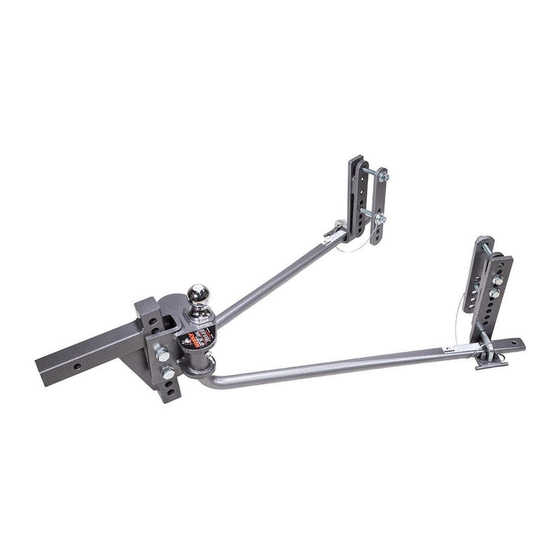
CENTER LINE FS SYSTEM
33310: CENTER LINE FS, 400-600 LBS. W/2-5/16" BALL
33311: CENTER LINE FS, 600-800 LBS. W/2-5/16" BALL
33312: CENTER LINE FS, 800-1200 LBS. W/2-5/16" BALL
DO NOT EXCEED RECOMMENDED TOWING LIMITS. SEE VEHICLE'S OWNER'S
MANUAL.
Use ONLY with 4", 5", 6", 7" & 8" trailer frames.
Part Number
Max. Tongue Weight
33310
400-600 lbs. / 181-272 kg.
33311
600-800 lbs. / 272-363 kg.
33312
800-1200 lbs. / 363-544 kg.
Part Number
Note: This system can be used on any angle tongue trailer.
Max. Gross Trailer Weight
NOT an individual bar
Max. Tongue Weight Max. Gross Trailer Weight
600 lbs. / 272 kg.
INSTALL TIME:
0.5-1 HOUR
6,000 lbs. / 2721 kg.
8,000 lbs. / 3629 kg.
12,000 lbs. / 5443 kg.
6,000 lbs. / 2721 kg.
Page-1
Advertisement

Related Manuals for Husky 33310


Summary of Contents for Husky 33310
- Page 1 INSTALL TIME: Maintenance Instructions 0.5-1 HOUR CENTER LINE FS SYSTEM 33310: CENTER LINE FS, 400-600 LBS. W/2-5/16” BALL 33311: CENTER LINE FS, 600-800 LBS. W/2-5/16” BALL 33312: CENTER LINE FS, 800-1200 LBS. W/2-5/16” BALL Dealer / Installer: Provide a copy of these instructions to the end user of this product. These instructions provide important operating and safety information for proper usage of this product.
-
Page 2: Tools Required For Installation
Weigh trailer again after fully loading and check loaded tongue and gross weight to ensure proper weight distribution hitch is being used. WARNING This kit is to ONLY be used with Husky weight distribution spring bars only that are designed for this particular system. Do not substitute with any other spring bars. WARNING Do not use a separate friction sway control on this unit! All Products limited to Vehicle Tow Rating, see Vehicle Owners Manual. - Page 3 Measure Trailer Coupler & Frame Height NOTE: Changing the weight of the trailer and/or tow vehicle by adding, moving or unloading cargo may require the need to adjust how the weight distribution system is set up. IMPORTANT! Set parking brake of tow vehicle and chock the wheels of the trailer before lifting or lowering! 1.
-
Page 4: Installation And Setup
Measure the Tow Vehicle For vehicles with air springs, air shocks or automatic leveling systems only: Check vehicle owner's manual or other instructions on these items. Unless otherwise indicated, air springs and air shocks should be deflated to their minimum recommended pressure BEFORE assembling and adjusting the weight distribution hitch. - Page 5 Un-screw the 5/8-11 hex bolt until the bottom of the bolt threads are flush to the inside of the channel. ILLUSTRATION 5 5/8-11 HEX HEAD BOLT Insert the shank into the receiver box. Hold the Center Line FS head assembly on the shank as shown and align so that the hitch ball is 1"...
- Page 6 Align the bottom hole on the channel to the hole on the shank. Place a ¾” washer onto the ¾” hex bolt. Then insert the bolt with washer through the bottom hole in the channel and through the shank. Remember the hole and orientation in these instructions are an example only, yours may be different.
- Page 7 The use of shims may be required to fill up the gap between the U channel and the shank. It is NOT necessary to have equal shims on either side. ILLUSTRATION 9 U channel Shim Tighten 5/8” hex bolt securely. Torque the 5/8” bolt to 50ft.lbs. Then, securely tighten the 5/8” jam nut.
- Page 8 10. Put a ¾” flat washer on the top ¾” hex bolt followed by a ¾” nylon lock nut. Put a ¾” flat washer on the bottom 3/4” hex bolt followed by a ¾” nylon lock nut. Torque the ¾” nylon lock nuts to 260 ft-lbs.
- Page 9 Your Center Line FS system should look like this now. ILLUSTRATION 13 Installing Frame Brackets Remove L-Pin, tether, and hair pin from the lift bracket. Remove the 1/2” hex flange bolts so the lift bracket can be removed from the frame bracket. ILLUSTRATION 14 Tether Frame Bracket...
- Page 10 Install both frame brackets and frame plates 28.5”-30.5” away from the center of ball socket on coupler on each side of the trailer frame. See Step 15 for frame bracket and plate assembly. ILLUSTRATION 15 28.5” – 30.5” Use the 1/2" carriage bolt, flat washer, lock washer and hex nut to hold the frame brackets in place using the top hole.
- Page 11 Install the lift bracket by adjusting the height of the lift bracket so that the measured distance from the ground to the spring bar support surface is (approximately) 3-1/2” from the top tip of the spring bar. (Dimension “A” = Dimension “B” +3-1/2”). This is a starting point, and you may need to make adjustments later.
- Page 12 Lift Tool Assembly 20. Insert lift bar into lift tool. 21. Insert M6 X 30mm hex head bolts into holes through handle assembly. 22. Place M6 flat washer onto hex bolts. 23. Place M6 lock washer onto M6 X 30 hex bolts. 24.
- Page 13 Spring bar loading on lift brackets To load the spring bar onto the lift bracket, orient the lift tool as shown below and come under the spring bar. Then, put the “finger” of the lift tool into the square hole on the lift bracket and using BOTH hands on the lift tool.
- Page 14 Once the spring bar is resting securely on the lift bracket insert the “L” retaining pin into the square hole and secure with the hair pin clip. ILLUSTRATION 20 WARNING Keep clear of the pivot path of all moving parts when there is tension on the spring bar. Maintain control of the lift tool at all times when raising or lowering the spring bar.
- Page 15 ILLUSTRATION 21 Properly Adjusted System Over Adjusted System Under Adjusted System Removing the spring bar from the lift bracket 30. Make sure the tow vehicle and the trailer are on level ground and are straight. Chock the trailer wheels and engage the emergency brake on the tow vehicle. All Products limited to Vehicle Tow Rating, see Vehicle Owners Manual.
- Page 16 Raise the trailer tongue enough to ease the force required to lift the spring bar ends off the lift brackets. Place the lift tool on the round peg on the forward side of the lift bracket and under the end of the spring bar as shown. Start pushing down on the lift tool. ILLUSTRATION 22 Continue pushing down on the lift tool until it starts to come up and towards you.
- Page 17 Remove the lift tool from under the spring bar and position it as shown below. Place the tip of the tool against the side of the frame; somewhere on the frame bracket or even on the lift bracket is fine. Then pull out on the handle (keeping hands away from the spring bar) until the spring bar falls off the lift bracket completely.
-
Page 18: Parts Listing
Parts Listing ILLUSTRATION 26 All Products limited to Vehicle Tow Rating, see Vehicle Owners Manual. Visit www.huskytow.com for Warranty Information / Tech Support / Product Updates. 2023 Keystone Automotive Operations Inc. All Rights Reserved. 2023-Rev4 Page-18... - Page 19 ITEM DESCRIPTION HEAD WELDMENT 9 HOLE, 10" LONG, 2" SQ. SHANK 5/8" HITCH PIN 5/8" HAIR PIN 400-600 LBS. CENTER LINE FS SPRING BAR 600-800 LBS. CENTER LINE FS SPRING BAR 800-1200 LBS. CENTER LINE FS SPRING BAR HOOK SHIM 3/4"...
- Page 20 If possible, wait for road conditions to improve before driving. Follow all state, local and provincial driving and towing laws in the location you are driving in. Not following your tow vehicle, trailer, and Husky instructions/manuals can result in a fatal accident. Check Your Equipment Please refer to the MAINTENANCE section.
- Page 21 Safety Chains Can Prevent Runaway Trailer in case hitch/coupler fails. Always use safety chains when towing. Cross safety chains under coupling to prevent tongue from dropping to ground. Allow only enough slack for tight turns. Do not let safety chains drag on ground. Twist safety chains equally from hook ends to take up slack.
- Page 22 Check All Trailer to Towing Vehicle Connections for Security and Operation NOTE: Surge brake are actuators not designed for use with a weight distributing hitch may bind and not operate freely. Check your surge brake operating instructions for any specific requirements regarding their use with weight distributing hitches.
-
Page 23: Warranty Terms
Husky Towing Products and Keystone Automotive Operations Inc. with proof of purchase by the original purchaser. The original purchaser shall pay all transportation and shipping costs associated with the return of the defective product and the defective product shall become the property of Keystone Automotive Operations Inc. - Page 24 D'INSTALLATION : 0,5-1 HEURE SYSTÈME FS LIGNE CENTRALE 33310: LIGNE CENTRALE FS, 400-600 LBS. CROCHET W/2-5/16 po 33311: LIGNE CENTRALE FS, 600-800 LBS. CROCHET W/2-5/16 po 33312: LIGNE CENTRALE FS, 800-1200 LBS. CROCHET W/2-5/16 po Revendeur / Fournissez une copie de ces instructions à...
- Page 25 AVERTISSEMENT Ce kit doit être utilisé UNIQUEMENT avec les barres de ressort de distribution de poids Husky qui sont conçues pour ce système particulier. Ne pas remplacer par d'autres barres à ressort. AVERTISSEMENT N'utilisez pas de commande de balancement à...
- Page 26 Mesurez la hauteur de l'attelage et du châssis de la remorque REMARQUE : La modification du poids de la remorque et/ou du véhicule tracteur par l'ajout, le déplacement ou le déchargement d'une cargaison peut nécessiter le réglage du système de répartition du poids.
- Page 27 Mesurez le véhicule de remorquage Pour les véhicules équipés de ressorts pneumatiques, d'amortisseurs pneumatiques ou de systèmes de mise à niveau automatique uniquement : Consultez le manuel du propriétaire du véhicule ou d'autres instructions sur ces éléments. Sauf indication contraire, les ressorts et amortisseurs pneumatiques doivent être dégonflés à...
- Page 28 Dévissez le boulon hexagonal 5/8-11 jusqu'à ce que le bas des filets du boulon affleure l'intérieur du canal. ILLUSTRATION 5 BOULON À TÊTE HEXAGONALE 5/8-11 Insérez la tige dans le boîtier de réception. Maintenez l'assemblage de la tête Center Line FS sur la tige comme indiqué...
- Page 29 Alignez le trou inférieur du canal sur le trou de la tige. Placez une rondelle de ¾ po sur le boulon hexagonal de ¾ po. Insérez ensuite le boulon avec la rondelle dans le trou inférieur du canal et dans la tige. Rappelez-vous que le trou et l'orientation dans ces instructions ne sont qu'un exemple, les vôtres peuvent être différents.
- Page 30 L'utilisation de cales peut être nécessaire pour combler l'espace entre le canal en U et la tige. Il n'est PAS nécessaire d'avoir des cales égales de chaque côté. ILLUSTRATION 9 Canal U Cale Serrez fermement le boulon hexagonal de 5/8 po. Serrez le boulon 5/8 po à 50ft.lbs. Puis, serrez fermement le contre-écrou de 5/8 po.
- Page 31 10. Placez une rondelle plate de ¾ po sur le boulon hexagonal supérieur de ¾ po, puis un écrou de blocage en nylon de ¾ po. Mettez une rondelle plate de ¾ po sur le boulon hexagonal inférieur de ¾ po, puis un écrou de blocage en nylon de ¾ po. Serrez les écrous de blocage en nylon de ¾" à 260 ft-lbs.
- Page 32 Votre système Center Line FS devrait maintenant ressembler à ceci. ILLUSTRATION 13 Installation des supports de cadre Retirez la tige en L, l'attache et la goupille du support de levage. Retirez les boulons à bride hexagonale de 1/2" pour que le support de levage puisse être retiré...
- Page 33 Installez les deux supports de cadre et les plaques de cadre à une distance de 28,5 po à 30,5 po du centre de la rotule sur chaque côté du châssis de la remorque. Consultez l'étape 15 pour l'assemblage du support et de la plaque du cadre. ILLUSTRATION 15 28.5 po –...
- Page 34 Installez le support de levage en réglant sa hauteur de manière à ce que la distance mesurée entre le sol et la surface de support de la barre à ressort soit (approximativement) de 3-1/2" à partir de l'extrémité supérieure de la barre à ressort (Dimension "A" = Dimension "B" +3-1/2"). Il s'agit d’un point de départ, et vous devrez peut-être faire des ajustements plus tard.
- Page 35 Assemblage de l'Outil de Levage 20. Insérez la barre de levage dans l'outil de levage. 21. Insérez les boulons à tête hexagonale M6 X 30 mm dans les trous de la poignée. 22. Placez une rondelle plate M6 sur les boulons hexagonaux. 23.
-
Page 36: Vue Arrière
Chargement de la barre à ressort sur les supports de levage Pour charger la barre à ressort sur le support de levage, orientez l'outil de levage comme indiqué ci-dessous et venez sous la barre à ressort. Placez ensuite le "doigt" de l'outil de levage dans le trou carré... - Page 37 Une fois que la barre à ressort repose fermement sur le support de levage, insérez la goupille de retenue en "L" dans le trou carré et fixez-la avec la pince à la goupille. ILLUSTRATION 20 AVERTISSEMENT Restez à l'écart de la trajectoire de pivotement de toutes les pièces mobiles lorsqu'il y a une tension sur la barre à ressort.
- Page 38 ILLUSTRATION 21 Système correctement ajusté Système surajusté Système sous-ajusté Retrait de la barre à ressort du support de levage 30. Vérifiez que le véhicule tracteur et la remorque sont sur un terrain plat et qu'ils sont droits. Calez les roues de la remorque et serrez le frein d'urgence du véhicule de remorquage. Tous les produits sont limités à...
- Page 39 Relevez suffisamment la flèche de la remorque pour atténuer la force nécessaire pour soulever les extrémités de la barre à ressort des supports de levage. Placez l'outil de levage sur la cheville ronde située sur le côté avant du support de levage et sous l'extrémité de la barre de ressort, comme illustré.
- Page 40 Retirez l'outil de levage de la partie inférieur de la barre à ressort et positionnez-le comme indiqué ci-dessous. Placez la pointe de l'outil contre le côté du cadre, quelque part sur le support du cadre ou même sur le support de l'élévateur est idéal. Tirez ensuite sur la poignée (en gardant les mains éloignées de la barre à...
-
Page 41: Liste Des Pièces
Liste des pièces ILLUSTRATION 26 Tous les produits sont limités à la capacité de remorquage du véhicule, voir le Manuel du Propriétaire du Véhicule. Consultez www.huskytow.com pour les informations sur la All Products limited to Vehicle Tow Rating, see Vehicle Owners Manual. Visit www.huskytow.com for Warranty Information / Tech Support / garantie / l'assistance technique / les mises à... - Page 42 ARTICLE DESCRIPTION N° SOUDURE DE TÊTE 9 TROUS, 10 po DE LONG, 2 po DE LARGE. TIGE TIGE D'ATTELAGE DE 5/8 po GOUPILLE DE 5/8 po 400-600 LBS. LIGNE CENTRALE FS BARRE À RESSORT 600-800 LBS. LIGNE CENTRALE FS BARRE À RESSORT 800-1200 LBS.
- Page 43 Respectez toutes les lois de conduite et de remorquage de l'État, de la région et de la province dans laquelle vous conduisez. Le non-respect des instructions/manuels relatifs au véhicule de remorquage, à la remorque et à Husky peut entraîner un accident mortel.
- Page 44 Chaînes de sécurité Peut empêcher l'emballement de la remorque en cas de défaillance de l'attelage/coupleur. Utilisez toujours des chaînes de sécurité lors du remorquage. Croisez des chaînes de sécurité sous l'attelage pour empêcher la languette de tomber au sol. Ne laissez que la marge nécessaire pour les virages serrés. Ne laissez pas les chaînes de sécurité...
- Page 45 Vérifiez la sécurité et le fonctionnement de toutes les connexions entre la remorque et le véhicule tracteur. REMARQUE : Les actionneurs des freins à inertie qui ne sont pas conçus pour être utilisés avec un attelage de répartition du poids peuvent se bloquer et ne pas fonctionner librement. Consultez le mode d'emploi de votre frein de surcharge pour connaître les exigences spécifiques concernant son utilisation avec les attelages à...
-
Page 46: Conditions De Garantie
être défectueux en termes de fabrication ou de matériel. Cette garantie ne s'applique pas à l'usure normale de la finition placée sur les produits Keystone Automotive Operations Inc. Husky Towing Products et Keystone Automotive Operations Inc. ne sont pas responsables des coûts de main-d'œuvre encourus pour le retrait ou le remplacement du produit défectueux.
Need help?
Do you have a question about the 33310 and is the answer not in the manual?
Questions and answers