
Related Manuals for Energie AQUAPURA MONOBLOC 120i


Summary of Contents for Energie AQUAPURA MONOBLOC 120i
- Page 1 TECHNICAL MANUAL AQUAPURA MONOBLOC 120i Revision: 00 Diretcives Version 0 2006/95/CE Date 15/06/2021...
- Page 3 Technical Manual MONOBLOC Esteemed Client, We would like to thank you for your choice when you acquired an equipment for sanitary water heating. AQUAPURA MONOBLOC aero-thermal system will surely meet all your expectations and provide many years of comfort with maximum power saving.
-
Page 4: Table Of Contents
Technical Manual MONOBLOC Index INTRO ......................6 1.1. Symbols..........................6 1.2. Safety Information ........................ 6 1.3. Information ..........................7 SPECIFICATIONS ..................9 2.1. Components .......................... 9 2.2. Running Principle ....................... 10 2.3. Technical Data ........................11 TRANSPORT ....................12 INSTALLATION..................12 4.1. - Page 5 Technical Manual MONOBLOC 9.4. Condensate circuit ......................28 9.5. Cleaning Air Circuit ......................28 9.6. Safety Thermostat ......................29...
-
Page 6: Intro
Technical Manual MONOBLOC 1. INTRO 1.1. Symbols Every process that the supplier believes to be conducive to harmful danger and/or material damage will be signalled with a danger sign. To better characterize the danger, the symbol will be followed by one of these words: •... -
Page 7: Information
Technical Manual MONOBLOC 1.3. Information INFORMATION Installation The installation of the equipment must be carried out by staff with suitable training and • qualified for this purpose. The device must not be installed: • o outdoors; o in places with corrosive environment; o in places with a risk of temperatures below 5ºC;... - Page 8 Communicate to the customer the fact that the alteration or maintenance of the device must only be carried out by specialized and accredited personnel. Components not supplied with the equipment. We strongly recommend its installation. To request additional information, contact us via the email address energie@energie.pt or via our website www.energie.pt.
-
Page 9: Specifications
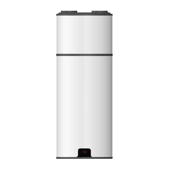
Technical Manual MONOBLOC 2. SPECIFICATIONS 2.1. Components The AquaPura Monobloc 120L package contains: Hot water storage heater, in stainless steel: • Dimensions: – Hot Water – Cold Water 1350 mm – Drain 808 mm – Backstop 693 mm 450 mm Ø530 mm 100 mm 550 mm... -
Page 10: Running Principle
Technical Manual MONOBLOC • A cooling system, at the top, responsible for transferring heat from ambient air to sanitary water; Air extraction duct Evaporator Compressor Expansion valve High pressure Solenoid valve switch Filter Low pressure switch Condensate drain Electrical box 2.2. -
Page 11: Technical Data
Technical Manual MONOBLOC 2.3. Technical Data Unit 120i Type of Equipment Air/Water Heat Pump for DHW Nominal Capacity Empty Weight Dimensions (ø/height) Ø530/1350 Storage Water Heater Material Stainless Steel Insulation High-density polyurethane 50mm ºC Max Running Temperature Max Working Pressure Test Pressure Heat Loss kWh/24h... -
Page 12: Transport
Technical Manual MONOBLOC 3. TRANSPORT The equipment must be carried in an upright position. The equipment must be raised and lowered with extreme care, to avoid impact that could damage the material. Make sure the belts and/or transportation straps do not damage the material. WARNING Always use suitable means to transport the material (pallet lift, forklift, etc.) The equipment must be transported in its original package to the place of installation. -
Page 13: Safety Group
Technical Manual MONOBLOC 4.1.5. Safety Group* The safety device allows the system to be protected against anomaly situations: cold water supply, hot water flowing back, emptying of the storage water heater and high pressure. The valve is calibrated to activate at 0.7 MPa). To drain the water in the storage water heater, you should close the supply valve and open the discharge valve. -
Page 14: Positioning
Technical Manual MONOBLOC 4.2. Positioning Before starting to assemble the equipment, check the support capacity of the wall and the material it is made of, considering the weight of the equipment filled with water. WARNING When placing the equipment in its position, bear in mind possible future interventions. Make sure that there is at least the following free space around the equipment: Min 400mm Min 600mm... -
Page 15: Air Inlet/Outlet Installation
Technical Manual MONOBLOC 4.3. Air Inlet/Outlet Installation As the AquaPura Monobloc absorbs heat during its operation, the air flow (inlet/out- let) must be directed to unheated areas. The equipment will cool the room where it is placed and so if it is installed in heater rooms, the air flow must be directed to other rooms and/or the outside. - Page 16 Technical Manual MONOBLOC Max Lenght Ducts Ø125 Ø150 Rigid duct Flexible duct Considering 90º curves and louvers at the air inlet and outlet of the equipment. If ducts are used, directing the air flow to areas that do not require heating, there are some options: Using Outside Air Min 500mm If outside air is used, the unit may be...
- Page 17 Technical Manual MONOBLOC Using Ambient and Outside Air A branched duct can be used to inflate air into the equipment. So you can get hot air in the summer, from the outside, and hot air in the winter from an unheated room. UNHEATED AREA HEATED OR min 50 m...
-
Page 18: Hydraulic Installation
Technical Manual MONOBLOC 4.4. Hydraulic Installation Caption 1 Shut Off Valve Drain Valve 2 Pressure Reducing Valve (3 bar / 0,3 MPa) Circulating Pump 3 Non-return Valve Thermostatic Mixing Valve 4 Safety group (7 bar / 0,7 MPa) A Cold Water Inlet 5 Drainage Siphon B Hot Water Outlet 6 Expansion Vessel... -
Page 19: Thermodynamic Group Access
Technical Manual MONOBLOC WARNING / DANGER The water you use may contain impurities and/or substances damaging to the system and even harmful to your health. Make sure you use water with quality fitting for home consumption. The following table indicates some parameters that, when exceeded, must be chemically treated. Hardness (ºdH) Treatment 3,0 - 20,0... -
Page 20: Condensates
Technical Manual MONOBLOC 4.6. Condensates During operation, condensation may occur. These condensates are collected in the drip tray and drained through a hole at the back of the tray. The installer must connect the condensate hose supplied by the manufacturer and direct the condensates to the drainage system or drainage siphon. The condensate hose must not be bent/pressed and must be placed where it best suits the proper flow of condensates. -
Page 21: Electrical Diagram
Technical Manual MONOBLOC 4.8. Electrical Diagram CAPTION Electrical backup heater High pressure switch Water temperature probe Low pressure switch Evaporator temperature probe Compressor VENT Fan Safety thermostat Solenoid valve Neutral Phase... -
Page 22: Control And Programming
Technical Manual MONOBLOC 5. CONTROL and PROGRAMMING 5.1. Control Panel The control panel is simple and intuitive. Allows the configuration of various operating parameters depending on the operating mode selected by the user. 5.2. Keys (Functions) Description ON/OFF Switch on and off controller; Exit menu, submenu or cancel a function;... -
Page 23: User Interface
Technical Manual MONOBLOC 5.4. User Interface 1 - ON/OFF equipment Press the key to turn on or turn off the equipment. Note: After turning on the equipment, you will have to wait 5 min until the equipment starts operating (compressor start timer). 2 - Block/ Unlock keyboard To unlock the keyboard, press the key for 4s. -
Page 24: Operating Modes
Technical Manual MONOBLOC 5.5. Operating Modes The heat pump is programmed to work in three modes of operation: ECO (ECONOMY) operating mode, the equipment works only as a heat pump to heat the water in the water heater. The operating setpoint adopted corresponds to parameter SP1. During ECO operating mode the compressor works in parallel with the fan and the electrical heater is always off. -
Page 25: Errors
Technical Manual MONOBLOC 6. ERRORS The installation, assembly and repair of the equipment can only be carried out by qualified technicians. Symbols Description Problem / Checking Probe 1 damaged Check integrity of probe connections on the controller; Measure probe resistance (NTC 10KΩ, resistance at 25°C equals ± Probe 2 damaged 10KΩ);... -
Page 26: Troubleshouting
Technical Manual MONOBLOC 8. TROUBLESHOUTING Problem Possible Causes How to Proceed Check the power supply. Falta de alimentação Check the corresponding circuit breaker. Failure in electronic board Cable damaged or Check the integrity of the electronic board’s disconnected electric circuit. Low temperature Adjust the temperature of the set-point. - Page 27 Technical Manual MONOBLOC Problem Possible Causes How to Proceed Low hot water flow Hydraulic circuit blocked Check the condition of the hydraulic circuit rate Absence or poor sizing of the expansion vessel Installation and/or correct sizing of an (if leakage is expansion vessel Water leakage by the intermittent)
-
Page 28: System Maintenance
Technical Manual MONOBLOC 9. SYSTEM MAINTENANCE Before undertaking any maintenance operation on the equipment, make sure it is not plugged to the power supply! Wait until the fan comes to a complete stop. WARNING Although the fluid in the cooling circuit is environmentally-friendly, it must not be released into the atmosphere. - Page 29 Technical Manual MONOBLOC 9.6. Safety Thermostat The safety thermostat is deactivated whenever there is an anomaly in the system, so every time you plan to activate it, find out what happened that caused it to change its status mode. If you were not able to determine what happened and it is still deactivated, contact customer service to have your problem solved.
- Page 30 NOTE: This sheet must be properly filled, signed and stamped by the installer / reseller and returned to ENERGIE EST, Lda., otherwise the warranty will not be validated. Send this installation sheet to warranty@energie.pt, writing the serial number of the equipment as subject.
- Page 31 Technical Manual MONOBLOC NOTES:...
Need help?
Do you have a question about the AQUAPURA MONOBLOC 120i and is the answer not in the manual?
Questions and answers