
Related Manuals for Energie BOOSTER 300


Summary of Contents for Energie BOOSTER 300
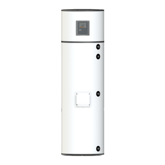
- Page 1 TECHNICAL MANUAL BOOSTER 300 Revision 0 Directivs Version 0 2006/95/CE Date 04/07/2023...
- Page 3 We would like to thank you for your choice when you acquired an equipment for sanitary water heating. Energie BOOSTER system will surely meet all your expectations and provide many years of comfort with maximum power saving. Our organization dedicates much time, energy and economic resources in order to develop innovations that will promote power saving in our products.
-
Page 4: Table Of Contents
Installation and users manual BOOST Index 1 INTRO ....................... 5 Symbols ........................5 Pre-installation Information ..................5 Safety Information ....................6 2 SPECIFICATIONS ..................7 Components ......................7 Running Principle ....................7 Technical Data......................8 3 TRANSPORT .................... 9 4 INSTALLATION ..................10 Safety and Control Devices ..................10 4.1.1 High/Low Pressure Switch ................10... - Page 5 Installation and user manual BOOSTER 6.6.2 VACATION Mode ..................30 Menu ........................30 Changing Mode ......................30 Number of Showers Available ................30 6.10 Consultation of probe temperatures (S1, S2, S3) ...........31 6.11 Source control flow ....................31 7 CHECKING GOOD RUNNING CONDITION ........... 31 8 PARAMETERS DESCRIPTION ..............
-
Page 6: Intro
Installation and users manual BOOST 1 INTRO 1.1 Symbols Every process that the supplier believes to be conducive to harmful danger and/or material damage will be signalled with a danger sign. To better characterize the danger, the symbol will be followed by one of these words: •... -
Page 7: Safety Information
Installation and user manual BOOSTER 1.3 Safety Information Every process that the supplier believes to be conducive to harmful danger and/or material damage will be signalled with a danger sign. To better characterize the danger, the symbol will be followed by one of these words: •... -
Page 8: Specifications
BOOST 2 SPECIFICATIONS 2.1 Components The Booster package contains: • Stainless steel water storage tank with electric heater. Dimensions: Ø Booster 300 Description Inch. 1968 G 3/4” M C – Cold Water Inlet G 1/2” F R - Recirculation G 1/2” F PT –... -
Page 9: Technical Data
The R134a is a HFC fluid, thus not harmful to the ozone layer. It has great chemical and thermal stability, low toxicity, non-inflammable, and is compatible with most materials. 2.3 Technical Data Unit BOOSTER 300 Type of Equipment Water/Water Heat Pump for DHW DHW Capacity Empty Weight Dimensions (ø/height) -
Page 10: Transport
Installation and users manual BOOST 3 TRANSPORT The equipment must be carried in an upright position. The equipment must be raised and lowered with extreme care, to avoid impact that could damage the material. Make sure the belts and/or transportation straps do not damage the material. WARNING Always use suitable means to transport the material (pallet lift, forklift, etc.) Correct transport position:... -
Page 11: Installation
Installation and user manual BOOSTER 4 INSTALLATION 4.1 Safety and Control Devices 4.1.1 High/Low Pressure Switch In case of running outside the range of pressures recommended and defined by the supplier, the equipment will switch off and indicate error in the electronic panel. 4.1.2 Safety Thermostat The safety thermostat is set by the supplier to ensure that the water temperature in the storage water tank with electric heater does not exceed the maximum value. -
Page 12: Drain Pan
Installation and users manual BOOST 4.2 Drain pan The equipment should not be installed over an area where drains from the tank or its connections could cause damage in the adjacent area or on the lower floors of the structure. For the aforementioned reasons, it is recommended to place a drain pan under the equipment. -
Page 13: Hydraulic Installation
Installation and user manual BOOSTER 4.4 Hydraulic Installation In the installation of the booster heat pump it is necessary to install the safety components presented below, however, an additional attention must be required on the booster heat source where a minimum water flow must be maintained of 100l/h to provide heat transfer. - Page 14 Installation and users manual BOOST Caption 1 Shut Off Valve Circulating Pump 2 Pressure Reducing Valve (3 bar / 0,3 MPa) Thermostatic Mixing Valve 3 Non-return Valve Cold Water Inlet 4 Safety group (7 bar / 0,7 MPa) Hot Water Outlet 5 Drainage Siphon Recirculation 6 Expansion Vessel...
-
Page 15: Installation Configuration
Installation and user manual BOOSTER 4.4.1 Water flow control valve This device is equipped with a water flow control valve that regulates the amount of water that enters the evaporator according the T3 and T2 probes. This control valve needs a minimum amount of water pressure in the circuit to regulate properly. -
Page 16: Valve Configuration
Installation and users manual BOOST Heat Sourc 4.5.2 Valve configuration In this configuration the radiant floor is parallel connected to the heat source where regulation valves are needed to ensure the correct water flow to the equipment and radiant floors. Heat Sourc 4.6 Condensates... -
Page 17: Electrical Connections
Installation and user manual BOOSTER During operation, condensation may occur. These condensates are collected in the drip tray and drained through a hole at the back of the tray. The installer must connect the condensate hose supplied by the manufacturer and direct the condensates to the drainage system or drainage siphon. The condensate hose must not be bent/pressed and must be placed where it best suits the proper flow of condensates. -
Page 18: Electrical Diagram
Installation and users manual BOOST 5 Electrical Diagram CAPTION ⏚ Electrical backup heater Ground Water temperature probe High pressure switch Heat source inlet Low pressure switch Heat source outlet COMP Compressor Flow control valve Safety thermostat Neutral TERM Compressor thermal Phase Solar thermal probe... -
Page 19: Control And Programming
Installation and user manual BOOSTER 6 CONTROL and PROGRAMMING 6.1 Control Panel The control panel of the BOOSTER heat pump is simple and intuitive. It enables the configuration of several operating parameters according to the operating mode selected by the user. It comprises six command keys (ON / OFF / CANCEL, MENU, COMP ▲, E-HEATER ▼, DISINFECT and OK / LOCK that enable checking the running of the equipment, consult and change parameters. -
Page 20: Display
Installation and users manual BOOST 6.3 Display 6.3.1 Interface 6.3.2 Symbols Description Equipment in ECO operating mode Equipment in AUTO operating mode Equipment in BOOST operating mode Timer clock control Compressor Motorized flow valve Electrical heater Disinfect Chrono function Vacation mode Recirculation pump function Solar function °C... -
Page 21: Symbols With Equipment Running
Installation and user manual BOOSTER 6.3.3 Symbols with Equipment Running Symbol Description Compressor ACTIVATED Compressor RUNNING Electrical heater ACTIVATED Electrical heater RUNNING Electrical heater ACTIVATED when S1 < P08 and/or P07 ˃ Temperature S3 (Auto Mode) Electrical heater ACTIVATED when compressor continuous running time exceeds T05 (Auto mode) Electrical heater ACTIVATED manually. -
Page 22: Start-Up Of The System
Installation and users manual BOOST 6.4 Start-up of the System Before starting, check whether the installation is set up according to the recommendations and that everything is in conformity, then you may plug your equipment to the power supply. After switching on your equipment by plugging it into the power supply, you should wait a few seconds until the controller begins to work. -
Page 23: Mode
Installation and user manual BOOSTER 6.5.1 Mode In ECO operating mode, the equipment runs only as a Heat Pump to heat the water in the storage water tank. Thus, we could generate a greater efficiency, and savings for the user. Every time the user feels it necessary, may switch on the support electrical heater, using this mode, manually pressing the key (E-HEATER). -
Page 24: Mode
Installation and users manual BOOST 6.5.4 Mode The TCC function provides the possibility of raising the water temperature when an alternative power source is available (solar photovoltaic, wind or other), increasing the efficiency of the heat pump and making the alternative power source profitable. To this end, it is sufficient to connect a cable from the inverter to the equipment's control board. -
Page 25: Chrono Scheduling Of The Heat Pump
Installation and user manual BOOSTER 6.5.5 Chrono scheduling of the heat pump The heat pump has an internal clock that allows the user to set two periods of operation for the control of the equipment. These periods can be distinctly defined as weekly (Monday to Friday) or weekend (Saturday and Sunday). -
Page 26: Chrono Scheduling Of The Recirculation Pump
Installation and users manual BOOST 6.5.6 Chrono scheduling of the recirculation pump The heat pump has an internal clock that allows the user to set two periods of operation for the pump of recirculation. These periods can be distinctly defined as weekly (Monday to Friday) or weekend (Saturday and Sunday). -
Page 27: Additional Functions
Installation and user manual BOOSTER 6.5.7 Additional functions The heat pump controller has four additional functions available. These functions allow the management/control of a solar thermal installation and pump of recirculation. To configure these functions, it is necessary to enter the installer level of access (F11), access the submenu parameters (F08) and select parameter P12. - Page 28 Installation and users manual BOOST Parameter P12 = 2: In the presence of a "SC" electronic control unit to control the solar thermal installation, it is possible to put the heat pump on standby whenever there is solar production, this is, when the solar thermal installation is producing the electronic control unit activates the auxiliary contact "CAUX"...
- Page 29 Installation and user manual BOOSTER Parameter P12 = 3: In the presence of a "SC" electronic control unit to control the solar thermal installation, it is possible to put the heat pump on standby whenever there is solar production, this is, when the solar thermal installation is producing the electronic control unit activates the auxiliary contact "CAUX"...
- Page 30 Installation and users manual BOOST Parameter P12 = 4: The heat pump controller assumes the control of a recirculation pump in parallel with the heat pump control. The pump of recirculation is driven by the hourly period set by the user and the temperature in the heat accumulator.
-
Page 31: Extra Modes
Installation and user manual BOOSTER 6.6 Extra Modes 6.6.1 DISINFECT The HPWS electronic control features the Disinfect function, which consists of a water heating cycle up to 65 °C, for a period of time long enough to prevent the formation of germs inside the tank. The Disinfect function can be set automatically or manually. -
Page 32: Consultation Of Probe Temperatures (S1, S2, S3)
Installation and users manual BOOST Relevant considerations: • The illustrative set presented above will not be visible on the display whenever the water temperature inside the tank is below 38ºC; • The number of available showers is calculated considering that one shower is approximately equivalent to a consumption of 50L of domestic hot water;... -
Page 33: Parameters Description
Installation and user manual BOOSTER 8 PARAMETERS DESCRIPTION Code Type Function Default Units Portuguese English Français Language Deutsch English Italiano Espanol Nederlands Clock Date and Time Week Chrono Heat Weekend Chrono = OFF Pump ON/ OFF chrono Chrono Week Recirculation Weekend Chrono = OFF Pump... - Page 34 Installation and users manual BOOST T07 (timer) – Delay time to compressor starts running after LP error T11 (timer) – Delay time LP alarm T12 (timer) – Delay time water flow alarm T13 (timer) – Delay time to restart the solar thermal pump T14 (timer) –...
-
Page 35: Errors
Installation and user manual BOOSTER 9 ERRORS The installation, assembly and repair of the equipment can only be carried out by qualified technicians. Symbol Description Problem / Checking Er01 – S1 Probe 1 OFF. Lack of temperature probe. Check for probe. Er02 –... -
Page 36: Probe Chart
Installation and users manual BOOST 10 PROBE CHART The probes installed in the equipment (S1, S2, S3 e S4) are NTC 10kΩ@25ºC. -
Page 37: Troubleshooting
Installation and user manual BOOSTER 11 TROUBLESHOOTING Problem Possible Causes How to Proceed Check the power supply Power supply failure Failure in electronic Check the corresponding circuit breaker Check the integrity of the electronic board’s board Cable damaged or disconnected electric circuit Low temperature Adjust the temperature of the set-point. - Page 38 Installation and users manual BOOST Problem Possible Causes How to Proceed Low hot water flow Hydraulic circuit blocked Check the condition of the hydraulic circuit rate Absence or incorrect sizing Installation and/or correct dimensioning of of expansion vessel (if leak expansion vessel Water discharge on the is not continuous)
-
Page 39: System Maintenance
Installation and user manual BOOSTER 12 SYSTEM MAINTENANCE Before undertaking any maintenance operation on the equipment, make sure it is not plugged to the power supply! WARNING Although the fluid in the cooling circuit is environmentally-friendly, it must not be released into the atmosphere. - Page 40 Installation and users manual BOOST...
- Page 41 NOTE: This sheet must be properly filled, signed and stamped by the installer / reseller and returned to ENERGIE EST, Lda., otherwise the warranty will not be validated. Send this installation sheet to warranty@energie.pt, writing the serial number of the equipment as subject.
- Page 42 Installation and users manual BOOST NOTES:...
- Page 43 Installation and user manual BOOSTER...
- Page 44 Installation and users manual BOOST...
Need help?
Do you have a question about the BOOSTER 300 and is the answer not in the manual?
Questions and answers