Table of Contents
Advertisement
Quick Links
EBDB • Setup Guide
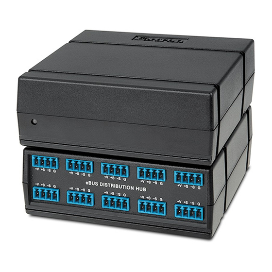
The Extron EBDB is an eBUS
eBUS ports, connected in parallel, which allows each port to act as an input or an output for communication between IPCP Pro
control processors and other eBUS devices. A front panel LED indicates when power is present on one or more of the ports.
The EBDB does not need to be set up. Other components of an eBUS-enabled system (an IPCP Pro control processor and eBUS
peripheral products such as EBPs [eBUS button panels]) must be configured using Extron Global Configurator (GC) software (in
GC Professional or GC Plus mode), which is available at www.extron.com.
Features
eBUS
Distribution
Ports
+
V
+
S
– S
G
+
V
+
V
+
S
+
– S
S
– S
G
G
+
e B
V
+
V
+
U S
S
+
S
– S
D IS
– S
G
T R
G
IB
+
U T
V
+
+
IO
V
S
N
+
– S
S
H U
– S
G
B
G
+
V
+
V
+
S
+
– S
S
– S
G
G
+
V
+
S
– S
G
EBDB Rear and Front Panel Features
Figure 1.
Cabling: eBUS Connections
Attach cables using the following diagrams as a guide. Extron STP20-2/1000 or STP20-2P/1000 cable is recommended for eBUS
connections.
ATTENTION:
Installation and service must be performed by authorized personnel only.
Power LED Indications
LED unlit — No power is present.
LED lit — Power is present.
eBUS port on an
IPCP Pro Control
Processor or an eBUS
endpoint device
Basic eBUS Wiring and Indications
Figure 2.
signal distribution hub for use with eBUS-enabled IP Link
®
Notches for
Securing
Tie Wrap
Power
LED
ZipClip
Mounting Slot
(front and rear)
Front Panel
Rear Panel
+
+
– S
+
+
– S
V
S
G
V
S
+
V
+
S
– S
G
+
V
+
S
– S
+V
+S
-S
G
G
-S
+S
+V
+
+
– S
+
+
– S
+
+
– S
G
V
S
G
V
S
G
V
S
G
eBUS DISTRIBUTION HUB
G
+
V
+
S
– S
G
+
V
+
S
– S
G
+
V
+
S
– S
G
+V
+S
-S
G
3/16" (5 mm) Max.
+V
+12 VDC
+S
+ Signal
-S
- Signal
G
Ground
Tie drain wires to ground.
Pro control processors. It includes ten
®
eBUS Connections
• Connect up to nine (9) eBUS endpoint devices
and one IPCP Pro control processor or ten
endpoint devices.
• Wire the connectors the same at both ends for
every eBUS device.
• Power is provided by the IPCP Pro or an
additional power supply.
eBUS port on an
EBP or other
eBUS endpoint
device
1
Advertisement
Table of Contents

Related Manuals for Extron electronics EBDB


Summary of Contents for Extron electronics EBDB
- Page 1 A front panel LED indicates when power is present on one or more of the ports. The EBDB does not need to be set up. Other components of an eBUS-enabled system (an IPCP Pro control processor and eBUS peripheral products such as EBPs [eBUS button panels]) must be configured using Extron Global Configurator (GC) software (in GC Professional or GC Plus mode), which is available at www.extron.com.
- Page 2 Connect the EBDB and any eBUS endpoint devices to each other in a daisy-chain or a star arrangement. Wire both ends of each cable the same (pin 1 to pin 1, pin 2 to pin 2, and so forth).
- Page 3 Pivot the other end down and press until the clip snaps into place. The EBDB is one quarter rack wide. Up to four EBDBs can be mounted side by side directly onto a rack shelf. Align the threaded holes in the bottom of the EBDB...
- Page 4 (Inside India Only) Extron USA - West Extron USA - East +31.33.453.4040 +91.80.3055.3777 +1.714.491.1500 +1.919.850.1000 +31.33.453.4050 FAX +91.80.3055.3737 FAX +1.714.491.1517 FAX +1.919.850.1001 FAX © 2016 Extron Electronics All rights reserved. All trademarks mentioned are the property of their respective owners. www.extron.com...
Need help?
Do you have a question about the EBDB and is the answer not in the manual?
Questions and answers