Table of Contents
Advertisement
Quick Links
Operations and Maintenance Manual
E-Mail: Info@KirbyMorgan.com, Web Site:www.KirbyMorgan.com
DANGER: Diving with compressed breathing gas is a hazardous activ-
ity. Even if you do everything right there is always the danger that you may
be killed or injured. No piece of diving equipment can prevent the possibility
that you may be killed or injured any time you enter the water.
Manual prepared by SaltShaker Marine Industries, Inc., Dive Lab, Inc., and KMDSI. 08/ 04.
NOTE: This manual is the most current for the SuperLite 17A/B Helmet.It is page dated August 2004. Future changes
will be shown on page III and the changed pages will carry the date of change. Previous manuals may not reflect
these updates.
The SuperLite-17A/B helmet is CE Approved #16309-01HH and meets or exceeds all performance
and testing requirements of all government and non-government testing agencies throughout the
world. It is approved for use on all commercial and military work underwater. Only Kirby Morgan
masks and helmets have achieved the CR (Commerial Rated) mark, the highest United States of
America rating.
SuperLite, Band Mask, KMB, KMB Band Mask, Kirby Morgan, DSI, Diving Systems International, EXO, SuperFlow and DECA
are all registered trademarks of Kirby Morgan Dive Systems, Inc. Use of these terms to describe products that are not manufactured
by KMDSI is not permitted.
The two dimensional images (such as photographs and illustrations) of our products are © copyrighted and trademarks of Kirby
Morgan Dive Systems, Inc. The three dimensional forms of our products are trademark/trade dress protected.
© Copyright 1970-2003 Kirby Morgan Dive Systems, Inc. All rights reserved. This manual is made available for the express use of
owner of this Kirby Morgan product. No part of this manual may be reproduced, stored in any retrieval system, or transmitted, or
used in any form or by any means, whether graphic, electronic, mechanical, photocopy, or otherwise by technology known or
unknown, without the prior written permission of Kirby Morgan Dive Systems, Inc.
®
SuperLite
KMDSI Part # 100-001
Kirby Morgan Dive Systems, Inc.
1430 Jason Way
Santa Maria, CA 93455, USA
Telephone (805) 928-7772, FAX (805) 928-0342
Document # 040809001, Aug. 2004
17A/B Helmet
™
Advertisement
Table of Contents

Related Manuals for Kirby Morgan SuperLite 17A/B


Summary of Contents for Kirby Morgan SuperLite 17A/B
- Page 1 © Copyright 1970-2003 Kirby Morgan Dive Systems, Inc. All rights reserved. This manual is made available for the express use of owner of this Kirby Morgan product. No part of this manual may be reproduced, stored in any retrieval system, or transmitted, or used in any form or by any means, whether graphic, electronic, mechanical, photocopy, or otherwise by technology known or unknown, without the prior written permission of Kirby Morgan Dive Systems, Inc.
- Page 2 UPER WARRANTY INFORMATION Kirby Morgan Dive Systems, Inc. warrants every new mask, helmet, or KMAC Air Control System to be free from defects in workmanship for a period of ninety (90) days from date of purchase. This warranty covers all metal, fiberglass, and plastic parts. This warranty does NOT cover rubber parts, communica- tions components, or headliners.
- Page 3 UPER RECORD OF CHANGES It is the responsibility of the owner of this product to register their ownership with Kirby Morgan Dive Systems, Inc., by sending the warranty card provided. This card is to establish registration for any necessary warranty work and as a means of communication that allows KMDSI to contact the user regarding this prod- uct.
-
Page 4: Table Of Contents
2.8 Diving Procedures ..........................22 2.8.1 Standing By to Dive ........................22 2.8.2 Attaching the Umbilical to the Harness ..................22 2.8.3 Diver Dons Helmet ........................22 © Copyright 1970-2004 Kirby Morgan Dive Systems, Inc. All rights reserved. Document # 040809001, Aug. 2004 PAGE... - Page 5 5.5.5 Lubricate Nose Block O-Rings (105, 106 (2)) ................39 5.5.6 Emergency Valve Assembly (58)....................40 5.5.7 Steady Flow/Defogger Valve (32-41) .................... 40 5.5.8 Bias Device (138c) ........................40 © Copyright 1970-2004 Kirby Morgan Dive Systems, Inc. All rights reserved. Document # 040809001, Aug. 2004 PAGE...
- Page 6 6.10.1 Standard Old Style Single Exhaust Whisker‘ PN# 510-554 ............65 6.10.2 Reinstalling the Whisker ......................66 6.10.3 Double Exhaust Whisker Cleaning and Overhaul, Whisker PN# 525-102 ........ 66 © Copyright 1970-2004 Kirby Morgan Dive Systems, Inc. All rights reserved. Document # 040809001, Aug. 2004 PAGE...
- Page 7 7.9.2.1 Latch Catch Mechanism Disassembly ..................86 7.9.2.2 Latch Catch Mechanism Reassembly ..................87 7.9.3 Neck Clamp Assembly ........................87 7.9.3.1 Neck Clamp Assembly Adjustment /Inspection ................. 87 © Copyright 1970-2004 Kirby Morgan Dive Systems, Inc. All rights reserved. Document # 040809001, Aug. 2004 PAGE...
- Page 8 APPENDIX A2.3 Helmet and Emergency Gas System Daily Setup and Functional Checklist ....122 APPENDIX A2.4 Supervisor’s Equipment Checks Prior to Entry into Water ..........127 APPENDIX A2.5 Supervisor’s In-Water Checks ..................130 VIII © Copyright 1970-2004 Kirby Morgan Dive Systems, Inc. All rights reserved. Document # 040809001, Aug. 2004 PAGE...
- Page 9 WARNING: Follow all the instructions in this manual carefully and heed all safety precau- tions. Improper use of this diving helmet could result in serious injury or death. © Copyright 1970-2004 Kirby Morgan Dive Systems, Inc. All rights reserved. Document # 040809001, Aug. 2004 PAGE...
- Page 10 DANGER: Diving is a life threatening occupation. Even if you do everything right you can still be killed or injured. None of the models of Kirby Morgan helmets or masks can prevent acci- dents, injuries or death due to improper training, poor-health, improper supervision, improper job requirements, improper maintenance or acts of God.
- Page 11 Kirby Morgan helmets and masks must not be used with oxygen breathing mixtures in excess of 50% by volume without first insuring all gas-transporting components have been cleaned for oxygen service. Components requiring lubrication, should only be lubricated with oxygen compatible lubricants such as and Christo Lube®, Flourolube®, or...
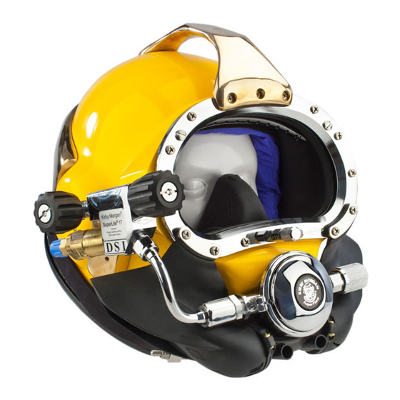
- Page 12 Fig. 1.1 The SuperLite-17B helmet with optional waterproof connector. Neck dam Note: Neck dam/yoke assembly is shown upside down for purposes of illus- tration only. Neck clamp Yoke strap © Copyright 1970-2004 Kirby Morgan Dive Systems, Inc. All rights reserved.
-
Page 13: General Information Chapter
They are not the part number. Next to the exploded drawing is a list of the “location” numbers that match the Kirby Morgan part numbers along with the name of the part. Always check the part number when ordering to make sure it is correct. -
Page 14: The Kirby Morgan Diving Helmets, Masks And Air Control System
SuperLite 17A/B Kirby Morgan 37 ™ ™ approved and marked approved and marked Neck Pad and Yoke and Latch Catch Sealed Pull Pins. Assembly PAGE © Copyright 1970-2004 Kirby Morgan Dive Systems, Inc. All rights reserved. Document # 040809001, Aug. 2004... - Page 15 The KMB 18 has a fiberglass frame (yellow) with smaller heads. while the KMB 28B frame is an extremely durable injec- tion molded plastic (black). © Copyright 1970-2004 Kirby Morgan Dive Systems, Inc. All rights reserved. Document # 040809001, Aug. 2004 PAGE...
- Page 16 Both models have a modular communications design that permits rapid and simple maintenance. The optional Hard Shell provides surfaces for mounting lights, cameras etc. PAGE © Copyright 1970-2004 Kirby Morgan Dive Systems, Inc. All rights reserved. Document # 040809001, Aug. 2004...
-
Page 17: Superlite 17A/B Design Features
The standard head cushion consists of a brushed ny- lon bag with an, open cell polyester foam inside © Copyright 1970-2004 Kirby Morgan Dive Systems, Inc. All rights reserved. Document # 040809001, Aug. 2004 PAGE... -
Page 18: General Description
. tion and maintenance of this valve must be done regu- PAGE © Copyright 1970-2004 Kirby Morgan Dive Systems, Inc. All rights reserved. Document # 040809001, Aug. 2004... - Page 19 To Regulator Gas Flow To Air Train Gas Supply Fig 1.6 The SuperLite 350 Demand Regulator Gas Flow Auxiliary L.P. Port To Regulator © Copyright 1970-2004 Kirby Morgan Dive Systems, Inc. All rights reserved. Document # 040809001, Aug. 2004 PAGE...
-
Page 20: Emergency Gas Supply System
The port is shipped plugged (48) at would cause a loss of the entire emergency gas delivery. This inflation capability does not significantly supply, Serious injury or death. PAGE © Copyright 1970-2004 Kirby Morgan Dive Systems, Inc. All rights reserved. Document # 040809001, Aug. 2004... -
Page 21: Helmet Attachment To The Diver
© Copyright 1970-2004 Kirby Morgan Dive Systems, Inc. All rights reserved. Document # 040809001, Aug. 2004 PAGE CAUTION: Pulling the neck dam over the... -
Page 22: Face Port Or Viewing Lens
Improperly manufactured parts can cause accidents resulting in serious injury or death PAGE © Copyright 1970-2004 Kirby Morgan Dive Systems, Inc. All rights reserved. Document # 040809001, Aug. 2004... -
Page 23: Chapter 2.0 Operating Instructions
The KMACS has a spe- © Copyright 1970-2004 Kirby Morgan Dive Systems, Inc. All rights reserved. Document # 040809001, Aug. 2004 PAGE... -
Page 24: First Use Of Superlite-17A/B
Ensure the chin strap is used. If the chin strap is not fastened or positioned properly, the helmet can float up on the diver’s head. This can make © Copyright 1970-2004 Kirby Morgan Dive Systems, Inc. All rights reserved. Document # 040809001, Aug. 2004 PAGE... -
Page 25: Pre Dress-In Procedure Utilize
(123d) must operate freely and should have no less than oral/nasal mask. 1/16” and no more than 1/8” inward travel before gas flow is heard. © Copyright 1970-2004 Kirby Morgan Dive Systems, Inc. All rights reserved. Document # 040809001, Aug. 2004 PAGE... -
Page 26: Preparing The Helmet For Diving
Exactly how the tank is carried, and the capacity of the tank, depends on the circumstances of the job, and company or personal preferences. © Copyright 1970-2004 Kirby Morgan Dive Systems, Inc. All rights reserved. Document # 040809001, Aug. 2004 PAGE... - Page 27 EGS pressure prior to each dive. © Copyright 1970-2004 Kirby Morgan Dive Systems, Inc. All rights reserved. Document # 040809001, Aug. 2004 PAGE...
-
Page 28: Setting Up To Dive
© Copyright 1970-2004 Kirby Morgan Dive Systems, Inc. All rights reserved. Document # 040809001, Aug. 2004 PAGE... -
Page 29: Opening The Helmet Breathing Gas Supply
This is standard on 17 A/B helmets starting in a distinct “pop”. Never twist the connectors, twisting will January 2004. damage the connection pins. © Copyright 1970-2004 Kirby Morgan Dive Systems, Inc. All rights reserved. Document # 040809001, Aug. 2004 PAGE... -
Page 30: Fogging Prevention
If the face port fails underwater, the helmet will flood and drowning may result. Fig. 2.10 Lift the yoke/neck dam over your head © Copyright 1970-2004 Kirby Morgan Dive Systems, Inc. All rights reserved. Document # 040809001, Aug. 2004 PAGE... - Page 31 Yoke/neck clamp assembly closure (A2.3 is comfortable on your head. Position the neck strap un- step 12) der your chin. © Copyright 1970-2004 Kirby Morgan Dive Systems, Inc. All rights reserved. Document # 040809001, Aug. 2004 PAGE...
- Page 32 If the chin strap is not fastened properly, the helmet will float up on the diver’s head. This can make the helmet very uncomfortable. © Copyright 1970-2004 Kirby Morgan Dive Systems, Inc. All rights reserved. Document # 040809001, Aug. 2004 PAGE...
- Page 33 (but under the handle) and secured in place. system properly. The yoke strap is standard on all 17 A/B helmets shipping after January 2004. It’s use is strongly recommended. © Copyright 1970-2004 Kirby Morgan Dive Systems, Inc. All rights reserved. Document # 040809001, Aug. 2004 PAGE...
-
Page 34: Testing The Breathing System
(120) if necessary. Press in on the purge button (123d) in the regulator cover (123b). This should produce a strong burst of breathing gas. © Copyright 1970-2004 Kirby Morgan Dive Systems, Inc. All rights reserved. Document # 040809001, Aug. 2004 PAGE... -
Page 35: Communications Check
(120) to ensure proper adjustment for the least and keeps the water out. Any incoming water is auto- breathing resistance. matically ejected. © Copyright 1970-2004 Kirby Morgan Dive Systems, Inc. All rights reserved. Document # 040809001, Aug. 2004 PAGE... -
Page 36: Inhalation Resistance
This action will break the seal of the neck ate danger of death by drowning or asphyxiation. dam around the base of the helmet and the neck dam and © Copyright 1970-2004 Kirby Morgan Dive Systems, Inc. All rights reserved. Document # 040809001, Aug. 2004 PAGE... -
Page 37: Storage Of The Helmet Between Dives, Ensure A2.6 Is Accomplished
(120) must be rotated (un- screwed) all the way out (counterclockwise) until the next dive. When the helmet is completely dry, or the diver is © Copyright 1970-2004 Kirby Morgan Dive Systems, Inc. All rights reserved. Document # 040809001, Aug. 2004 PAGE... - Page 38 2 - O HAPTER PERATING NSTRUCTIONS Notes © Copyright 1970-2004 Kirby Morgan Dive Systems, Inc. All rights reserved. Document # 040809001, Aug. 2004 PAGE...
-
Page 39: Chapter 3.0 Troubleshooting
(165) is y t i wiggled back and forth. r c i r c i i t c © Copyright 1970-2004 Kirby Morgan Dive Systems, Inc. All rights reserved. Document # 040809001, Aug. 2004 PAGE... -
Page 40: One Way Valve Malfunction
. l a . y l 3.4 SIDE BLOCK MALFUNCTION YMPTOMS ROBABLE AUSE EMEDY . f f l l i l l i © Copyright 1970-2004 Kirby Morgan Dive Systems, Inc. All rights reserved. Document # 040809001, Aug. 2004 PAGE... -
Page 41: Demand Regulator Malfunction
' r c i l . l a i t c © Copyright 1970-2004 Kirby Morgan Dive Systems, Inc. All rights reserved. Document # 040809001, Aug. 2004 PAGE... -
Page 42: Water Leakage Into Helmet
HAPTER ROUBLESHOOTING 3.6 WATER LEAKAGE INTO HELMET YMPTOMS ROBABLE AUSE EMEDY (160) 3.7 EGS VALVE MALFUNCTION YMPTOMS ROBABLE AUSE EMEDY l l i © Copyright 1970-2004 Kirby Morgan Dive Systems, Inc. All rights reserved. Document # 040809001, Aug. 2004 PAGE... -
Page 43: Chapter 4.0 Inspection Maintenance Timetable For Superlite-17 A/B
See Section 5.5 for additional details of monthly maintenance. 4.3 ANNUAL OR 400 OPERATING HOURS Use Appendix A2.1 SL 17-B Recommended Annual Maintenance, Inspection and Overhaul © Copyright 1970-2004 Kirby Morgan Dive Systems, Inc. All rights reserved. Document # 040809001, Aug. 2004 PAGE... - Page 44 N O T E S © Copyright 1970-2004 Kirby Morgan Dive Systems, Inc. All rights reserved. Document # 040809001, Aug. 2004 PAGE...
-
Page 45: Section 5.0 General Preventative Maintenance
KMDSI at (805) 928-7772 or Dive Lab at (850) #2 Phillips blade screwdriver 235-2715. 7/64 inch Allen wrench driver 9/64 inch Allen wrench driver 5/32 inch Allen wrench driver © Copyright 1970-2004 Kirby Morgan Dive Systems, Inc. All rights reserved. Document # 040809001, Aug. 2004 PAGE... - Page 46 Failure to use the equipment is used. recommended torque specifications could lead to helmet failure and accidents. This could re- sult in serious injury or death. © Copyright 1970-2004 Kirby Morgan Dive Systems, Inc. All rights reserved. Document # 040809001, Aug. 2004 PAGE...
-
Page 47: General Cleaning And Inspection Procedures
If contact occurs, rinse eyes place O-rings if any damage is found or suspected. with copious amounts of water and consult medi- cal help immediately. © Copyright 1970-2004 Kirby Morgan Dive Systems, Inc. All rights reserved. Document # 040809001, Aug. 2004 PAGE... -
Page 48: 2General Cleaning Guidelines
Place all parts and components in a clean 1-800-MSA-2222 washbasin or sink and immerse in detergent solution. Allow parts/components to soak for at least five minutes, © Copyright 1970-2004 Kirby Morgan Dive Systems, Inc. All rights reserved. Document # 040809001, Aug. 2004 PAGE... -
Page 49: Daily Maintenance/Lubrication
2) Place a protective cap over both the air inlet (67) and the Emergency Gas Valve inlet (50) to prevent foreign matter from entering the valves. © Copyright 1970-2004 Kirby Morgan Dive Systems, Inc. All rights reserved. Document # 040809001, Aug. 2004 PAGE... - Page 50 (123) and in the regulator body (112) through the air delivery tube located in the oral na- sal (83). © Copyright 1970-2004 Kirby Morgan Dive Systems, Inc. All rights reserved. Document # 040809001, Aug. 2004 PAGE...
-
Page 51: Monthly Maintenance
© Copyright 1970-2004 Kirby Morgan Dive Systems, Inc. All rights reserved. Document # 040809001, Aug. 2004 PAGE... -
Page 52: Emergency Valve Assembly (58)
It should be between 1/16” – 1/8” (1.5 – 3.0 mm). Adjust if necessary, per Section 6.8.10. Reinstall the diaphragm, the cover and the clamp. © Copyright 1970-2004 Kirby Morgan Dive Systems, Inc. All rights reserved. Document # 040809001, Aug. 2004 PAGE... -
Page 53: Chapter 6 Breathing System Maintenance And Repairs
(60) in a soft jaw vise while removing the seat (66) with a wrench. © Copyright 1970-2004 Kirby Morgan Dive Systems, Inc. All rights reserved. Document # 040809001, Aug. 2004 PAGE... -
Page 54: Reassembly Of The One-Way Valve
240 inch lbs . 3) Next, install the new O-ring (64) and new wiper (65) on the seat (66). Thread the seat into the valve body. © Copyright 1970-2004 Kirby Morgan Dive Systems, Inc. All rights reserved. Document # 040809001, Aug. 2004 PAGE... -
Page 55: Side Block Assembly
A machine screw is also adjacent the stud. The bent tube to remove the side block. screw does some securing but its main function is to pre- © Copyright 1970-2004 Kirby Morgan Dive Systems, Inc. All rights reserved. Document # 040809001, Aug. 2004 PAGE... -
Page 56: Disconnecting The Hose Assembly (17A)
Be sure to peel or scrape the old silicone sealant away from both sealing surfaces before reassembling. © Copyright 1970-2004 Kirby Morgan Dive Systems, Inc. All rights reserved. Document # 040809001, Aug. 2004 PAGE... -
Page 57: Side Block Assembly Replacement
Read and follow all precautions listed on the silicone sealant tube. Allow silicone to cure for a minimum of 24 hours before using your helmet. © Copyright 1970-2004 Kirby Morgan Dive Systems, Inc. All rights reserved. Document # 040809001, Aug. 2004 PAGE... -
Page 58: Defogger Valve
13/16 inch Open-end torque wrench attachment Torque Wrench The defogger valve components are disassembled as follows: Fig. 6.12 The side block valve assemblies. © Copyright 1970-2004 Kirby Morgan Dive Systems, Inc. All rights reserved. Document # 040809001, Aug. 2004 PAGE... -
Page 59: Cleaning And Lubricating Use Section 5.3.2
6) Torque the bonnet (36) with a torque wrench to ( 75 inch lbs). (see Fig. 6.19) Fig. 6.17 © Copyright 1970-2004 Kirby Morgan Dive Systems, Inc. All rights reserved. Document # 040809001, Aug. 2004 PAGE... -
Page 60: Emergency Valve Assembly (58)
Defogger valve control knob (34). The Emergency Valve Assembly (58) is not built into the side block. It is a separate component that can be re- © Copyright 1970-2004 Kirby Morgan Dive Systems, Inc. All rights reserved. Document # 040809001, Aug. 2004 PAGE... -
Page 61: Cleaning (See Section 5.3.2 And Lubricating Section 5.3.1)
If the valve is being cleaned and inspected in place proceed to 6.5.2. Fig. 6.25 © Copyright 1970-2004 Kirby Morgan Dive Systems, Inc. All rights reserved. Document # 040809001, Aug. 2004 PAGE... -
Page 62: Reassembly Of Emergency Valve (50)
Check to be certain the valve is tight by 3) Holding these components in place on the stem, screw the stem into the emergency gas valve body. © Copyright 1970-2004 Kirby Morgan Dive Systems, Inc. All rights reserved. Document # 040809001, Aug. 2004 PAGE... -
Page 63: Bent Tube Assembly
6.6.2 Removal of the Bent Tube Assembly Tools Required: 11/16 inch Open-end Attachment on Torque Wrench 7/8 inch Open-end Attachment on Torque Wrench 7/8 inch Open-end Wrench © Copyright 1970-2004 Kirby Morgan Dive Systems, Inc. All rights reserved. Document # 040809001, Aug. 2004 PAGE Fig .6.30... -
Page 64: Inspection Of Bent Tube Assembly
6.7.2 Hose Assembly Inspection “A style side block” Inspect the hose fittings for slippage and thread damage. © Copyright 1970-2004 Kirby Morgan Dive Systems, Inc. All rights reserved. Document # 040809001, Aug. 2004 PAGE... -
Page 65: O-Ring Replacement
For the gas inlet valve and adjustment system to operate properly, the components in the demand regulator MUST be in good condition and MUST be periodically adjusted © Copyright 1970-2004 Kirby Morgan Dive Systems, Inc. All rights reserved. Document # 040809001, Aug. 2004 PAGE... -
Page 66: Inspection Of Regulator Body Interior
Tools Required: 1/4 inch Flat Blade Attachment on Torque Screwdriver 1) On the demand regulator remove the demand regulator © Copyright 1970-2004 Kirby Morgan Dive Systems, Inc. All rights reserved. Document # 040809001, Aug. 2004 PAGE... -
Page 67: Demand Regulator Bias Adjustment Servicing, Demand Regulator On The Helmet
3/4 inch Open-end Wrench Attachment on Torque Wrench 3/32 inch Punch & Small Block of Wood Ball-Peen Hammer Regulator Adjustment Tool Kit, Part #525-620 Torque Wrench Fig. 6.38 © Copyright 1970-2004 Kirby Morgan Dive Systems, Inc. All rights reserved. Document # 040809001, Aug. 2004 PAGE... -
Page 68: Reassembly Of Adjustment System
(113) back in the regulator adjustment tube, fol- out the spacer (115), spring set (114), and piston (113). lowed by the spring set (114), and spacer (115). © Copyright 1970-2004 Kirby Morgan Dive Systems, Inc. All rights reserved. Document # 040809001, Aug. 2004 PAGE... -
Page 69: Demand Regulator Assembly Removal From Helmet
Diaphragm (122) 510-553 Inlet Nipple O-ring (133) 510-014 Exhaust valve (137) 510-552 Fig. 6.43 1) Remove the clamp screw (124) and clamp (125). © Copyright 1970-2004 Kirby Morgan Dive Systems, Inc. All rights reserved. Document # 040809001, Aug. 2004 PAGE... -
Page 70: Inspection Of Demand Regulator Parts
(126) on the inlet valve (134). Loosen and re- valve soft seat (134a ) should be replaced. move the adjustment nut (126) by rotating the socket wrench counterclockwise. © Copyright 1970-2004 Kirby Morgan Dive Systems, Inc. All rights reserved. Document # 040809001, Aug. 2004 PAGE... -
Page 71: Cleaning And Inspection Of Demand Regulator Parts
3) Press the head of the inlet valve (134) into the castle wrench (Part #525-618). Place the spring (135), and Fig. 6.49 Fig. 6.48 © Copyright 1970-2004 Kirby Morgan Dive Systems, Inc. All rights reserved. Document # 040809001, Aug. 2004 PAGE... - Page 72 NOTE: If this maintenance is during an annual over- knob. haul, replace the Teflon ring (44b) at the side block end © Copyright 1970-2004 Kirby Morgan Dive Systems, Inc. All rights reserved. Document # 040809001, Aug. 2004 PAGE...
-
Page 73: Tuning The Regulator
1 3/8” socket and an extension, torque the regu- has stopped. lator mount nut (82) to 75 inch pounds. Next using a torque © Copyright 1970-2004 Kirby Morgan Dive Systems, Inc. All rights reserved. Document # 040809001, Aug. 2004 PAGE... -
Page 74: Important Notes On Regulator Adjustment
11) To bend the lever down, place the disk end of the (see Note in Section 6.8.11 below) KMDSI 1/4 ” wrench onto the flat area of the adjustment © Copyright 1970-2004 Kirby Morgan Dive Systems, Inc. All rights reserved. Document # 040809001, Aug. 2004 PAGE... -
Page 75: Regulator Steady Flows When Pressured Up - Key Items To Check Per Section 6.8.10
Depress the lever several times to ensure the regu- regulator still steady flows the regulator requires adjust- lator is stabilized. ment per Section 6.8.10. © Copyright 1970-2004 Kirby Morgan Dive Systems, Inc. All rights reserved. Document # 040809001, Aug. 2004 PAGE... -
Page 76: Oral/Nasal
SL-17 and is intended aged it must be replaced. to replace all other exhaust systems previously employed. © Copyright 1970-2004 Kirby Morgan Dive Systems, Inc. All rights reserved. Document # 040809001, Aug. 2004 PAGE... -
Page 77: Standard Old Style Single Exhaust Whisker' Pn# 510-554
A new valve can then be installed. The valve should be replaced during scheduled overhauls or at least once a year. © Copyright 1970-2004 Kirby Morgan Dive Systems, Inc. All rights reserved. Document # 040809001, Aug. 2004 PAGE... -
Page 78: Reinstalling The Whisker
1/4 inch Screw Flat Blade Attachment. 7/8” Torque Wrench 0-200 ft lb packing nut (107) to 20 inch pounds. 7/8” Crow Foot Adapter © Copyright 1970-2004 Kirby Morgan Dive Systems, Inc. All rights reserved. Document # 040809001, Aug. 2004 PAGE... - Page 79 5). 19) Clean and inspect the nose block O-rings (106), shaft © Copyright 1970-2004 Kirby Morgan Dive Systems, Inc. All rights reserved. Document # 040809001, Aug. 2004 PAGE...
-
Page 80: Tri-Valve Exhaust® Whisker
4) Removal of a Tri-Valve Exhaust® System will require Exhaust® main body out to whiskers (140a,140b). the tie wrap that holds the Tri-Valve Exhaust® Main Body © Copyright 1970-2004 Kirby Morgan Dive Systems, Inc. All rights reserved. Document # 040809001, Aug. 2004 PAGE... - Page 81 3) Lightly lubricate a new O-ring (81) and place on the regulator inlet tube then thread the retaining nut (82) on hand tight only. © Copyright 1970-2004 Kirby Morgan Dive Systems, Inc. All rights reserved. Document # 040809001, Aug. 2004 PAGE...
-
Page 82: Exhaust Assembly
(149) to the helmet shell (92). moved except if replacing due to corrosion or damage. Below is the procedure for removal and replacement. Fig. 6.67 Fig. 6.69 © Copyright 1970-2004 Kirby Morgan Dive Systems, Inc. All rights reserved. Document # 040809001, Aug. 2004 PAGE... -
Page 83: Main Exhaust Body Replacement
1) Apply silicone sealant Dow Corning® RTV 732 Multi a 50/50 solution of vinegar and fresh water. Cleaning for © Copyright 1970-2004 Kirby Morgan Dive Systems, Inc. All rights reserved. Document # 040809001, Aug. 2004 PAGE... -
Page 84: Overpressure Relief Valve Disassembly And Cleaning
15 minutes. cleaned, overhauled or any time the valve is tested. 6) Using the nylon toothbrush, brush all components to © Copyright 1970-2004 Kirby Morgan Dive Systems, Inc. All rights reserved. Document # 040809001, Aug. 2004 PAGE... - Page 85 Note: Be sure to read caution on next venting at a pressure below 180- 200 p.s.i.g. (12.40-13.78 page! bar), secure the air supply and adjust the adjustment screw © Copyright 1970-2004 Kirby Morgan Dive Systems, Inc. All rights reserved. Document # 040809001, Aug. 2004 PAGE...
- Page 86 Installation in a high-pressure port will lead to loss of EGS supply and possible serious personal injury if the valve fails. NOTES © Copyright 1970-2004 Kirby Morgan Dive Systems, Inc. All rights reserved. Document # 040809001, Aug. 2004 PAGE...
-
Page 87: Chapter 7.0 Corrective Maintenance
7.9.4. 2) Visually inspect all metal parts of the clamp assembly for damage. Check the hinge pins for a loose fit, signs of PAGE © Copyright 1970-2004 Kirby Morgan Dive Systems, Inc. All rights reserved. Document # 040809001, Aug. 2004... -
Page 88: Nose Block Assembly
A larger pad of rubber can also be for camera or light mounting. glued onto this pad. PAGE © Copyright 1970-2004 Kirby Morgan Dive Systems, Inc. All rights reserved. Document # 040809001, Aug. 2004... -
Page 89: Handle Replacement
732 or equivalent Multi Purpose sealant on the rear mount surface of the handle and in the mount screw hole in the helmet shell (92). PAGE © Copyright 1970-2004 Kirby Morgan Dive Systems, Inc. All rights reserved. Document # 040809001, Aug. 2004... -
Page 90: Weight Replacement
7) Allow 24 hours for the sealant to cure before using the ficult. If you are hasty you may damage the helmet shell. helmet. PAGE © Copyright 1970-2004 Kirby Morgan Dive Systems, Inc. All rights reserved. Document # 040809001, Aug. 2004... -
Page 91: Alignment Sleeve
NOTE: Wrap a rag around the nose block knob while removing to sion or degradation; replace if questionable / required. prevent chrome damage when turning with pliers. PAGE © Copyright 1970-2004 Kirby Morgan Dive Systems, Inc. All rights reserved. Document # 040809001, Aug. 2004... -
Page 92: Face Port And Nose Block Replacement
2) Lightly lubricate the O-ring (144) with DC111 lubri- cant or equivalent per Section 5.3.1 and replace in the helmet shell (92). Fig. 7.12 PAGE © Copyright 1970-2004 Kirby Morgan Dive Systems, Inc. All rights reserved. Document # 040809001, Aug. 2004... - Page 93 12 inch pounds of and the O-ring (144) has completely sealed the face port (143). PAGE © Copyright 1970-2004 Kirby Morgan Dive Systems, Inc. All rights reserved. Document # 040809001, Aug. 2004...
-
Page 94: Special Note Regarding Ports
(155) and replacing the entire unit. If a wire and sliding the earphones out from underneath them. is broken it can usually be cleaned and soldered. PAGE © Copyright 1970-2004 Kirby Morgan Dive Systems, Inc. All rights reserved. Document # 040809001, Aug. 2004... -
Page 95: Earphone Removal And Replacement
(155). If you are using the optional connector use the following procedure. terminal block (154) this may be where the wires from the earphone and microphone are connected. PAGE © Copyright 1970-2004 Kirby Morgan Dive Systems, Inc. All rights reserved. Document # 040809001, Aug. 2004... -
Page 96: Connector Removal
Read and follow all precautions listed on the silicone sealant tube. Allow at least 24-hour cure time before using the helmet. PAGE © Copyright 1970-2004 Kirby Morgan Dive Systems, Inc. All rights reserved. Document # 040809001, Aug. 2004... -
Page 97: Neck Clamp/Yoke Assembly
6) Wipe off all the excess silicone sealant from the helmet screws. Thoroughly inspect all threaded surfaces for cor- shell (92). rosion or degradation; replace if questionable / required. PAGE © Copyright 1970-2004 Kirby Morgan Dive Systems, Inc. All rights reserved. Document # 040809001, Aug. 2004... -
Page 98: Yoke Replacement And Reassembly
3) With the helmet resting face down on the face port, Fig. 7.27 PAGE © Copyright 1970-2004 Kirby Morgan Dive Systems, Inc. All rights reserved. Document # 040809001, Aug. 2004... -
Page 99: Latch Catch Mechanism Reassembly
The clamp PAGE © Copyright 1970-2004 Kirby Morgan Dive Systems, Inc. All rights reserved. Document # 040809001, Aug. 2004... - Page 100 O-ring area of the helmet. When an authorized KMDSI Service Center must accomplish closing the lever, the lever should get tight at the mid- this procedure. PAGE © Copyright 1970-2004 Kirby Morgan Dive Systems, Inc. All rights reserved. Document # 040809001, Aug. 2004...
-
Page 101: Neck Dam
For this reason the pre-84 neck dams are not as popular as the drawstring type. Fig. 7.31 PAGE © Copyright 1970-2004 Kirby Morgan Dive Systems, Inc. All rights reserved. Document # 040809001, Aug. 2004... - Page 102 (Rubber side in-cloth out, with the outer edge rolled up towards the clamp). Fig. 7.33 Fig. 7.35 PAGE © Copyright 1970-2004 Kirby Morgan Dive Systems, Inc. All rights reserved. Document # 040809001, Aug. 2004...
- Page 103 Allow to set for at least 24 hours, then remove one screw the large reinforcing patch. apply thread locker, and torque to 30 inch pounds. Repeat PAGE © Copyright 1970-2004 Kirby Morgan Dive Systems, Inc. All rights reserved. Document # 040809001, Aug. 2004...
-
Page 104: O-Ring Seal Replacement
NOTE: You may find it easier to pull the tab through this space by tying a separate loop of string through the tab and feeding it through first. PAGE © Copyright 1970-2004 Kirby Morgan Dive Systems, Inc. All rights reserved. Document # 040809001, Aug. 2004... -
Page 105: Head Cushion Foam Replacement
“snapped back” into the interior helmet shell Fig. 7.39 using the snap tabs (78) installed. Note: If the head moves, the helmet should follow. PAGE © Copyright 1970-2004 Kirby Morgan Dive Systems, Inc. All rights reserved. Document # 040809001, Aug. 2004... - Page 106 7 - C HAPTER ORRECTIVE AINTENANCE NOTES PAGE © Copyright 1970-2004 Kirby Morgan Dive Systems, Inc. All rights reserved. Document # 040809001, Aug. 2004...
-
Page 107: Chapter 8 Accessories
Loosen the jam nut (131b) at the regula- Fig. 8.2 tor. If the bent tube will not swivel freely, you must loosen the large nut at the regulator. © Copyright 1970-2004 Kirby Morgan Dive Systems, Inc. All rights reserved. Document # 040809001, Aug. 2004 PAGE... - Page 108 18) Reinstall the one-way valve and using a torque wrench tighten to 150 inch pounds. 9) Slide the corrugated tube over the bent tube. The completed Hot Water Shroud installation. © Copyright 1970-2004 Kirby Morgan Dive Systems, Inc. All rights reserved. Document # 040809001, Aug. 2004 PAGE...
-
Page 109: Low Pressure Inflator Hose
2) Check the O-ring on the low-pressure whip to be sure it is present and in good condition. © Copyright 1970-2004 Kirby Morgan Dive Systems, Inc. All rights reserved. Document # 040809001, Aug. 2004 PAGE... -
Page 110: Weld Lens & Weld Shield Assemblies
(Fig 8.9 Weld Lens Assembly, Fig sion can result in serious personal injury or 8.10 Weld shield assembly). death. of the diver! © Copyright 1970-2004 Kirby Morgan Dive Systems, Inc. All rights reserved. Document # 040809001, Aug. 2004 PAGE... -
Page 111: Use Of Quick Disconnect
8) Install the regulator in the helmet, with the regulator assembly . mount nut hand tight. © Copyright 1970-2004 Kirby Morgan Dive Systems, Inc. All rights reserved. Document # 040809001, Aug. 2004 PAGE... - Page 112 13) Tighten the regulator mount nut and bent tube attach- ments. 14) Reinstall the oral/nasal and nose block device. © Copyright 1970-2004 Kirby Morgan Dive Systems, Inc. All rights reserved. Document # 040809001, Aug. 2004 PAGE...
- Page 113 This can be fatal, depending on the type of contaminant to which the diver is ex- posed. © Copyright 1970-2004 Kirby Morgan Dive Systems, Inc. All rights reserved. Document # 040809001, Aug. 2004 PAGE...
- Page 114 8 - A HAPTER CCESSORIES Notes © Copyright 1970-2004 Kirby Morgan Dive Systems, Inc. All rights reserved. Document # 040809001, Aug. 2004 PAGE...
- Page 115 Kirby Morgan Dive Systems, Inc. 1430 Jason Way, Santa Maria, CA 93455 USA 530-317 Phone: 805/928-7772 Fax: 805/928-0342 545-016 Air Train www.KirbyMorgan.com e-mail: info@KirbyMorgan.com 100 530-535 Washer © 2004 Kirby Morgan Dive Systems, Inc. All Rights Reserved Docu # 040809001, Aug. 2004...
- Page 116 Kirby Morgan Dive Systems, Inc. ® 1430 Jason Way, Santa Maria, CA 93455 USA Phone: 805/928-7772 Fax: 805/928-0342 www.KirbyMorgan.com e-mail: info@KirbyMorgan.com © 2004 Kirby Morgan Dive Systems, Inc. All Rights Reserved Docu # 040809001, Aug. 2004...
-
Page 117: Table Of Equivalents
2.036 Quarts Gallons 0.25 Square Feet Square Inches Temperature ( F - 32) Temperature ( 0.5555 Tons (U.S.) Pounds 2000 Watts Horsepower 0.001341 © Copyright 1970-2004 Kirby Morgan Dive Systems, Inc. All rights reserved. Document # 040809001, Aug. 2004 PAGE... -
Page 118: Appendix 1 Torque Specifications
, e l t a l t e l , e l t a l , t u t a l , t l © Copyright 1970-2004 Kirby Morgan Dive Systems, Inc. All rights reserved. Document # 040809001, Aug. 2004 PAGE... -
Page 119: Appendix A2
O-rings and com- use. ponents providing they pass a visual inspection per Sec- tion 5.3.1. When conducting annual or scheduled over- © Copyright 1970-2004 Kirby Morgan Dive Systems, Inc. All rights reserved. Document # 040809001, Aug. 2004 PAGE... - Page 120 Use of lubricants can attract and hold debris that could interfere with the proper operation of the regula- tor. © Copyright 1970-2004 Kirby Morgan Dive Systems, Inc. All rights reserved. Document # 040809001, Aug. 2004 PAGE...
- Page 121 © Copyright 1970-2004 Kirby Morgan Dive Systems, Inc. All rights reserved. This manual is made available for the express use of owner of this Kirby Morgan product. No part of this manual may be reproduced, stored in any retrieval system, or transmitted, or used in any form or by any means, whether graphic, electronic, mechanical, photocopy, or otherwise by technology known or unknown, without the prior written permission of Kirby Morgan Dive Systems, Inc.
- Page 122 (4). After neck clamp is adjusted, torque the Nylock lock nut (6) 50 inch pounds. Repair/replace parts as necessary. See SL-17 A/B O&M Manual 7.9.3.1 © Copyright 1970-2004 Kirby Morgan Dive Systems, Inc. All rights reserved. Document # 040809001, Aug. 2004 PAGE...
- Page 123 O&M Manual. 6. Disassemble the swing tongue catch Assembly, clean, and inspect all components. Replace components as necessary and reassemble, See O&M Manual. © Copyright 1970-2004 Kirby Morgan Dive Systems, Inc. All rights reserved. Document # 040809001, Aug. 2004 PAGE...
- Page 124 O & M Manual. NOTE: If using the Double Exhaust Whisker refer to applicable section of the pertinent O & M Manual © Copyright 1970-2004 Kirby Morgan Dive Systems, Inc. All rights reserved. Document # 040809001, Aug. 2004 PAGE...
- Page 125 If the adjustment nut is reused, the regulator may not maintain proper adjustment. See applicable O& M Manual 3. Re-assemble the demand regulator. See applicable O&M Manual. © Copyright 1970-2004 Kirby Morgan Dive Systems, Inc. All rights reserved. Document # 040809001, Aug. 2004 PAGE...
- Page 126 Best practice if the inlet nipple requires replacement; replace the soft seat as well. © Copyright 1970-2004 Kirby Morgan Dive Systems, Inc. All rights reserved. Document # 040809001, Aug. 2004 PAGE...
-
Page 127: Appendix A2.2 Monthly Inspection And Maintenance Checklist
8. Perform a leak check of all EGS components and fittings using soapy water in a pressurized condition. Repair/replace items as necessary. 9. Inspect the Harness Assembly for signs of wear and/or damage. Repair/replace as necessary. © Copyright 1970-2004 Kirby Morgan Dive Systems, Inc. All rights reserved. Document # 040809001, Aug. 2004 PAGE... - Page 128 Kirby Morgan helmet or mask by the owners/users of Kirby Morgan products. This copyrighted material may not be used in any way by any others without written permission.
- Page 129 © Copyright 1970-2004 Kirby Morgan Dive Systems, Inc. All rights reserved. This manual is made available for the express use of owner of this Kirby Morgan product. No part of this manual may be reproduced, stored in any retrieval system, or transmitted, or used in any form or by any means, whether graphic, electronic, mechanical, photocopy, or otherwise by technology known or unknown, without the prior written permission of Kirby Morgan Dive Systems, Inc.
- Page 130 7/16 inch deep well socket with a torque wrench. Ensure lock nut (6) is torqued to 60 inch pounds. Repair/replace and/or adjust parts as necessary. See Section 7.9.3.1 17A/B O&M Manual. © Copyright 1970-2004 Kirby Morgan Dive Systems, Inc. All rights reserved. Document # 040809001, Aug. 2004 PAGE...
- Page 131 Any damage requires an inspection by an Authorized KMDSI Technician. See Applicable O&M Manual. 7. Check the swing tongue catch for worn or damage parts and components. See O&M manual. © Copyright 1970-2004 Kirby Morgan Dive Systems, Inc. All rights reserved. Document # 040809001, Aug. 2004 PAGE...
- Page 132 Ensure the valve material is not hardened, distorted, and/ or warped. Replace the valve if questionable. Reinstall the cover. See applicable O&M manual. © Copyright 1970-2004 Kirby Morgan Dive Systems, Inc. All rights reserved. Document # 040809001, Aug. 2004 PAGE...
- Page 133 NOTE: The Emergency Gas System consists of a good quality first stage regulator equipped with, an Over-Pressure Bleed/Relief Valve, and an emergency gas supply hose that connects to the Emergency Valve on the helmet Side Block. © Copyright 1970-2004 Kirby Morgan Dive Systems, Inc. All rights reserved. Document # 040809001, Aug. 2004 PAGE...
-
Page 134: Appendix A2.3 Helmet And Emergency Gas System Daily Setup And Functional Checklist
Repair/replace items as necessary. 7. Inspect the harness assembly for signs of wear or damage. Repair/replace as necessary. Technician Signature: Date Comments: © Copyright 1970-2004 Kirby Morgan Dive Systems, Inc. All rights reserved. Document # 040809001, Aug. 2004 PAGE... - Page 135 Should any questions on proce- dures, components, or repairs arise, please contact Kirby Morgan Dive Systems, Inc., by telephone at (805) 928-7772 or via e-mail at info@kmdsi.com, or contact Dive Lab, Inc., by telephone at (850) 235-2715 or via e-mail at divelab@aol.com.
- Page 136 © Copyright 1970-2004 Kirby Morgan Dive Systems, Inc. All rights reserved. This manual is made available for the express use of owner of this Kirby Morgan product. No part of this manual may be reproduced, stored in any retrieval system, or transmitted, or used in any form or by any means, whether graphic, electronic, mechanical, photocopy, or otherwise by technology known or unknown, without the prior written permission of Kirby Morgan Dive Systems, Inc.
- Page 137 Test-mate the Neck Dam Ring Assembly to the helmet and check for proper adjustment. d. Ensure the sealed pull pins work properly. © Copyright 1970-2004 Kirby Morgan Dive Systems, Inc. All rights reserved. Document # 040809001, Aug. 2004 PAGE...
- Page 138 Check for gas escaping from the One-Way Valve, If any gas flow is detected the One-Way valve should be overhauled or replaced. © Copyright 1970-2004 Kirby Morgan Dive Systems, Inc. All rights reserved. Document # 040809001, Aug. 2004 PAGE...
-
Page 139: Appendix A2.4 Supervisor's Equipment Checks Prior To Entry Into Water
Note comments or discrepancies below in the comments 12. Tender section. Log maintenance in the applicable maintenance log. Technician Signature: Date _______________ Comments:__________________________________________________________________ ___________________________________________________________________________ © Copyright 1970-2004 Kirby Morgan Dive Systems, Inc. All rights reserved. Document # 040809001, Aug. 2004 PAGE... - Page 140 NOTE: The Maintenance Log, Appendix 3, of the Operations and Maintenance Manual may be used as a tem- plate for creating blank pages to record all the maintenance performed. © Copyright 1970-2004 Kirby Morgan Dive Systems, Inc. All rights reserved. Document # 040809001, Aug. 2004 PAGE...
- Page 141 © Copyright 1970-2004 Kirby Morgan Dive Systems, Inc. All rights reserved. This manual is made available for the express use of owner of this Kirby Morgan product. No part of this manual may be reproduced, stored in any retrieval system, or transmitted, or used in any form or by any means, whether graphic, electronic, mechanical, photocopy, or otherwise by technology known or unknown, without the prior written permission of Kirby Morgan Dive Systems, Inc.
-
Page 142: Appendix A2.5 Supervisor's In-Water Checks
Boots, gloves, knife, and other accessories. functioning correctly. The helmet/mask must f. Helmet supply pressure, minimum 115 p.s.i.g. be breathing easily and properly. © Copyright 1970-2004 Kirby Morgan Dive Systems, Inc. All rights reserved. Document # 040809001, Aug. 2004 PAGE... - Page 143 Should any questions on procedures, components, or repairs arise, please contact Kirby Morgan Dive Systems, Inc., by telephone at (805) 928-7772 or via e-mail at info@kmdsi.com, or contact Dive Lab, Inc., by telephone at (850) 235-2715 or via e-mail at divelab@aol.com.
- Page 144 Kirby Morgan, SuperLite, Band Mask, KMB Band Mask, EXO, SuperMask, SuperFlow, and Rex are all registered trademarks of Kirby Morgan Dive Systems, Inc. Use of these terms to describe products that are not manufactured by KMDSI is not permitted without written permission from KMDSI.
- Page 145 Should any questions on procedures, components, or repairs arise, please contact Kirby Morgan Dive Systems, Inc., by telephone at (805) 928-7772 or via e-mail at info@kmdsi.com, or contact Dive Lab, Inc., by telephone at (850) 235-2715 or via e-mail at divelab@aol.com.
- Page 146 Kirby Morgan, SuperLite, Band Mask, KMB Band Mask, EXO, SuperMask, SuperFlow, and Rex are all registered trademarks of Kirby Morgan Dive Systems, Inc. Use of these terms to describe products that are not manufactured by KMDSI is not permitted without written permission from KMDSI.
- Page 147 Should any questions on procedures, components, or repairs arise, please contact Kirby Morgan Dive Systems, Inc., by telephone at (805) 965- 8538 or via e-mail at info@kmdsi.com, or contact Dive Lab, Inc., by telephone at (850) 235-2715 or via e-mail at divelab@aol.com.
- Page 148 -17 A/B M PPENDICES UPER ANUAL © Copyright 1970-2004 Kirby Morgan Dive Systems, Inc. All rights reserved. Document # 040809001, Aug. 2004 PAGE...
Need help?
Do you have a question about the SuperLite 17A/B and is the answer not in the manual?
Questions and answers