Table of Contents
Advertisement
Quick Links
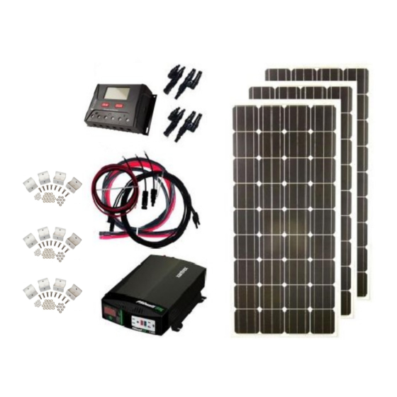
Grape Solar 540-Watt Off-Grid Kit
Visit www.grapesolar.com/manuals.html
www.grapesolar.com
Tel. 1-877-264-1014 (toll free), 1-541-349-9000, Fax: 1-541-343-9000
(GS-540-KIT-BT)
Installation Guide
For Additional Information
Or Email ino@grapesolar.com
©Copyright 2017, Grape Solar, Inc. All Rights Reserved
GS-540-KIT-BT PHOTOVOLTAIC POWER
GENERATION SYSTEM
CONFIGURATION MANUAL Rev. 170201
Valid from Jan. 2017
1
Advertisement
Table of Contents

Related Manuals for Grape Solar GS-540-KIT-BT


Summary of Contents for Grape Solar GS-540-KIT-BT
- Page 1 CONFIGURATION MANUAL Rev. 170201 Grape Solar 540-Watt Off-Grid Kit (GS-540-KIT-BT) Installation Guide For Additional Information Visit www.grapesolar.com/manuals.html Or Email ino@grapesolar.com ©Copyright 2017, Grape Solar, Inc. All Rights Reserved www.grapesolar.com Valid from Jan. 2017 Tel. 1-877-264-1014 (toll free), 1-541-349-9000, Fax: 1-541-343-9000...
- Page 2 5-foot red/black bare-wire-to-ring-lug cable pair (charge-controller-to-battery 10AWG) a 5-foot red/black cable pair (battery-to-inverter 4AWG) a Xantrex SW2000 inverter 3 sets of Grape Solar Zippity-Feet mounting brackets www.grapesolar.com Valid from Jan. 2017 Tel. 1-877-264-1014 (toll free), 1-541-349-9000, Fax: 1-541-343-9000...
- Page 3 GS-540-KIT-BT PHOTOVOLTAIC POWER GENERATION SYSTEM CONFIGURATION MANUAL Rev. 170201 Step 2: For optimum output, place the panels so they are fac- Step 3: Mount the 40BT controller if desired (note that it must ing due south at approximately the same angle as your be in a NEMA-4 rated enclosure if it is outdoors).
- Page 4 GS-540-KIT-BT PHOTOVOLTAIC POWER GENERATION SYSTEM CONFIGURATION MANUAL Rev. 170201 Step 5: Continued from last page. Step 6: Connect the solar connector outputs of the T-branch connect- ors to the solar connector on 15-foot extension cables. 3-panel T-branch connection Step 8: Connect the bare wire end of the red cable to the “PV Posi- Step 7: Then connect the solar connector outputs of the tive”...
Need help?
Do you have a question about the GS-540-KIT-BT and is the answer not in the manual?
Questions and answers