Table of Contents
Advertisement
Quick Links
Advertisement
Table of Contents

Related Manuals for QubicaAMF Highway 66

Summary of Contents for QubicaAMF Highway 66
- Page 1 Copyright 2 0 0 6 Qubic a Am f Worldw ide V e rsion 1 .3...
- Page 3 R1.3 November 2006 Add part list for Overload Andre Hebert Document Information Sheet Document name Release Date Author Highway 66 User manual second Edition R1_1.doc May 2005 Andre Hebert Highway 66 User manual second Edition R1_3.doc May 2006 Andre Hebert...
- Page 4 QubicaAmf. Changes are periodically made to the information herein; these changes will be incorporated in new editions of the publication. QubicaAmf may make improvements and / or changes in the product(s) and / or the program(s) described in this publication at any time.
-
Page 6: Table Of Contents
List of Procedures..........................10 IMPORTANT SAFETY INSTRUCTIONS..................11 Introduction to Highway 66 .................12 What Makes up the Highway 66 System....................13 Identifying Your Highway 66 System Components................14 Understanding how the Game is played....................15 About This Book ........................... 15 About This Book ........................... - Page 7 SW2-5 Pinsetter Reaction on Gutter Ball (V1.00) ..................34 SW2-6 Type of Game (V1.00)........................34 SW2-7 Number Pins Installed (V1.11) ......................34 Procedures and Adjustments ......................... 35 Taking Care of Your Highway 66 ..............43 Preventive Maintenance Basics......................44 Manufacturer’s Recommendations......................44 Setting up a Preventive Maintenance Program....................44 Getting Organized ..........................
- Page 8 TABLE OF CONTENTS Bowling Pin Highway ........................... 72 Main Components ..........................74 Frame Assembly............................ 76 Drawbar Assembly..........................78 311-1100-00 DC Motor Assembly......................80 9122015 Drawbar Shaft assembly......................82 9122027 Reel Arm assembly ........................ 84 9122057 Pulley Detection Assembly ....................86 9122070 Pin Brake Assembly .......................
-
Page 9: List Of Figures
LIST OF FIGURES List of Figures Figure 2-1 Dip Switch Location ....................31 Figure 2-2 Ball detector......................... 35 Figure 2-3 Pin Detector Button ..................... 36 Figure 2-4 Reel Arm Position......................36 Figure 2-5 - Optical Sensor Position ..................... 37 Figure 2-6 - String Repair ......................38 Figure 2-7 - Pin Brake Adjustment .................... -
Page 10: List Of Procedures
LIST OF PROCEDURES List of Procedures Procedure 2-1 - Ball detector:......................35 Procedure 2-2 - Strings Adjustment ....................36 Procedure 2-3 - LOS Limit Optical Sensor ................... 37 Procedure 2-4 - BOS Brake Optical Sensor ................. 37 Procedure 2-5 - PPOS Pin Pause Optical Sensor ................. 37 Procedure 2-6 - Repairing String and Bushing................ -
Page 11: Important Safety Instructions
IMPORTANT SAFETY INSTRUCTIONS Warning TO REDUCE THE RISK OF FIRE OR ELECTRICAL SHOCK, DO NOT EXPOSE THIS EQUIPMENT TO RAIN OR MOISTURE. HIGH VOLTAGE IS PRESENT IN THE PINSETTER POWER BOX. THE MAIN CIRCUIT BREAKERS MUST ALWAYS BE SHUT OFF OR THE TWIST LOCK PLUG DISCONNECTED PRIOR TO REMOVING THE POWER BOX COVER. -
Page 12: Introduction To Highway 66
Your Highway 66 machines are to be custom installed by a trained QubicaAmf Worldwide authorized technician. He/she will provide you with recommended products for use with your Highway 66 and instruct you in the proper operating and maintenance techniques. -
Page 13: What Makes Up The Highway 66 System
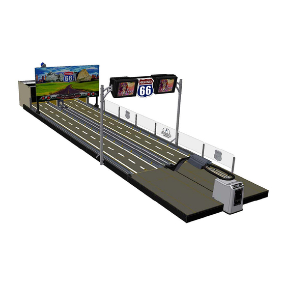
INTRODUCTION TO HIGHWAY 66 What Makes up the Highway 66 System The structure of the Highway 66 system is based on a wooden truss foundation with prefabricated lanes. The lane surface is of a hard-wearing synthetic material, designed to withstand the most extreme operating conditions and providing the operator with the minimum amount of maintenance. -
Page 14: Identifying Your Highway 66 System Components
INTRODUCTION TO HIGHWAY 66 Identifying Your Highway 66 System Components... -
Page 15: Understanding How The Game Is Played
INTRODUCTION TO HIGHWAY 66 Understanding how the Game is played Highway 66 is delivered with a CD rom containing different games; more games will be available with time. Check with your QubicaAmf representative to see which games are available now. -
Page 16: About This Book
A description of the wide variety of resources available from QubicaAmf to assist you in the use of your equipment is also included along with instructions on how to obtain additional information about QubicaAmf products. -
Page 17: Safety Information
It is the responsibility of the attendant to provide his or her own travel, lodging and school expenses. Anyone interested in attending a factory training school should contact their local QubicaAmf sales or service representative. 1. Always open the circuit breaker or disconnect the power plug from the electrical box before looking for, and clearing, any problem. -
Page 19: Highway 66 Fundamentals
Highway 66 Fundamentals Chapter Overview This chapter provides an overview of your Highway 66 machine. After reading this chapter you should be able to identify the major components of your Highway 66 and understand the basic principles of the machine’s operation. -
Page 20: Major Components And Assemblies
When the unit is turned on, the pins are set on the lane and the pinsetter is placed in a ball one situation. Let’s begin by taking a look at operation of your Highway 66 as it goes through a game. With ten pins set on the lane, the bowler rolls the first ball. -
Page 21: Pinsetter
HIGHWAY 66 FUNDAMENTALS Pinsetter Contrary to the ball being removed from the pit area and returned to the bowler, the pins remain at the rear and are re-spotted for the next delivery. The equipment used to control the flow of pins is called a pinsetter. -
Page 22: Pin Stabilizer
HIGHWAY 66 FUNDAMENTALS Pin Stabilizer Mounted below the pinsetter is the stabilizer assembly which absorbs most of the vibration and then stabilizes each pin before its descent to the lane. The stabilizer assembly is a very important part of the pinsetter. Without it, the pins would have to be picked up much gentler than they are and the untangling mode would lose its powerful effect. -
Page 23: Solenoid/Opto Control Box
HIGHWAY 66 FUNDAMENTALS Solenoid/Opto Control Box Mounted at the front of each pinsetter is the solenoid/opto control box (SB-9802300-10) and the pin detection wheels (one for each pin). These wheels are activated (rotated) by their corresponding strings when a pin is knocked down. Each wheel has holes in it and the wheel itself rotates through an optical sensor (SB-ECIL-325-PD). -
Page 24: Optical Reading Devices
HIGHWAY 66 FUNDAMENTALS Optical Reading Devices Ball Detector With the pinsetter in a ready to bowl position, the ball detector allows for the detection of the ball on its way down the lane. Once a ball is detected, the reading pause commences. -
Page 25: Q-Ams Game Controller
HIGHWAY 66 FUNDAMENTALS Q-AMS Game Controller Located on the wooden board between the two machines the Q-AMS is the game controller. It does include a CD drive that enables the use of different games. The Q- AMS have connections to the TMS Power Box, to the two monitors above the lanes and to the I/O controller located inside the ball rack at the player end. -
Page 26: Understanding How The System Works
HIGHWAY 66 FUNDAMENTALS Understanding how the System Works When the pinsetter is turned on, it will perform a calibration cycle. Then the pins are set on the lane and the pinsetter is placed in a ball one situation. The bowler rolls the ball which passes through the ball detector's infrared beam of light thus sending a signal to the pinsetter control box. -
Page 27: Pinsetter Cycles
HIGHWAY 66 FUNDAMENTALS Pinsetter Cycles After a slight pause, the drawbar will commence its downward cycle. The TMS Pinsetter will then perform one of two different types of cycles: Part Set The pinsetter sets only the pins which weren't knocked down on the lane, the shield raises and the lane is ready for the next ball. -
Page 29: Setting Up/Operating Your Highway 66
2. Setting Up/Operating Your Highway 66 Chapter Overview This chapter provides step-by-step instructions for setting up and configuring your equipment in order to meet your needs and requirements along with instructions for the day-to-day use and management of your equipment. -
Page 30: Getting Ready To Play
SETTING UP/OPERATING YOUR HIGHWAY 66 Getting Ready to Play! Please refer to the game manual for the special set-up function of each individual’s games. Each game has its own set-up menu where you can choose different options such as: •... -
Page 31: Tms Power Box Dip Switches
SETTING UP/OPERATING YOUR HIGHWAY 66 TMS power box DIP switches The following tables describe the various DIP switch functions. The version in which the setting was introduced or changed is indicated in brackets following the description. The shaded areas indicate the preset factory settings. -
Page 32: (Sw1-3,4,5) Pin Detection Sensitivity
SETTING UP/OPERATING YOUR HIGHWAY 66 (SW1-3,4,5) Pin Detection Sensitivity These dip switches are used to set the pin detector wheels' sensitivity. In order for the pinsetter to detect a pin as fallen, a specific quantity of holes located on the pin detector wheels must pass through its corresponding optical sensor. -
Page 33: Sw2-1, 2 Untangle Routine Type (V1.00)
Used to determine if the pinsetters will come back ON after a power failure if they were ON before. Note: The reaction will be different if they are in Manual mode or in Highway 66 or Standard mode. Reaction in autoscoring mode SW1-2 in OFF position and Standard mode SW2-6 OFF Pinsetters will stay OFF and you will have to manually power ON the pinsetter. -
Page 34: Sw2-4 Pin Position When Pinsetters Are Off (V1.00)
SETTING UP/OPERATING YOUR HIGHWAY 66 SW2-4 Pin Position when Pinsetters are OFF (V1.00) Used to determine if the pinsetters will close with all ten pins on the deck, or it will raise all the pins up and keep them in this position. -
Page 35: Procedures And Adjustments
SETTING UP/OPERATING YOUR HIGHWAY 66 Procedures and Adjustments Procedure 2-1 - Ball detector: The ball detector is a simple, very reliable stand alone device but may become misaligned once in a while due to the constant vibration caused by the balls rolling down the lane. Located in front of the kickback, it communicates to the pinsetter control box through a cable assembly. -
Page 36: Figure 2-3 Pin Detector Button
SETTING UP/OPERATING YOUR HIGHWAY 66 Procedure 2-2 - Strings Adjustment A good strings adjustment is the key for the proper operation of the TMS pinsetter. Before attempting any other adjustment please perform the string adjustment. 1. If it is not already ON, power on the pinsetter. -
Page 37: Figure 2-5 - Optical Sensor Position
SETTING UP/OPERATING YOUR HIGHWAY 66 Procedure 2-3 - LOS Limit Optical Sensor This limit optical sensor is used to tell the TMS power box when the drawbar reach is in the upper position during the calibration process. The position of that sensor is fixed, and you should not attempt to move it. -
Page 38: Figure 2-6 - String Repair
SETTING UP/OPERATING YOUR HIGHWAY 66 Procedure 2-6 - Repairing String and Bushing 1. Raise the front cover of the pinsetter and press the Power On button. The pinsetter will start up and set the pins on the lane 2. Open the circuit breaker located on the power box between the two pinsetters. -
Page 39: Figure 2-7 - Pin Brake Adjustment
SETTING UP/OPERATING YOUR HIGHWAY 66 Procedure 2-7 - Adjusting the Pin Brakes 1. Raise the front cover of the pinsetter and press the Power On button. The pinsetter will start up and set the pins on the lane. 2. Press button #1 (PS Brake). The drawbar will move to the rear of the pinsetter and each pin brake will be activated. -
Page 40: Figure 2-8 - Drawbar Chain Adjustment
SETTING UP/OPERATING YOUR HIGHWAY 66 Procedure 2-9 - Adjusting Chain Tension of the Drawbar 1. Make sure that the drawbar is in the D2 (UP) position. 2. Open the main circuit breaker located on the power box situated between the two pinsetters. -
Page 41: Figure 2-9 Adjusting Rear Ball Lift V-Belt
SETTING UP/OPERATING YOUR HIGHWAY 66 Procedure 2-10 - Adjusting Rear Ball Lift V-Belt Adjust tension of the V-belt in order to have a span of 3/8 to 1/2” with 5 pounds of pressure on the middle of the belt. Use the Adjusting Screw to raise or lower the motor assembly. -
Page 43: Taking Care Of Your Highway 66
3. Taking Care of Your Highway 66 Chapter Overview This chapter contains information about the proper handling and care of your equipment. -
Page 44: Preventive Maintenance Basics
Always supply your equipment’s serial number when placing an order. Setting up a Preventive Maintenance Program The simplicity of QubicaAmf equipment being its main characteristic, it is very easy to understand its concept. At the same time, it must be understood that equipment of any kind requires a minimum of maintenance and should operate according to standards. -
Page 45: Getting Organized
There are services that must be performed daily, weekly, monthly, and quarterly. QubicaAmf strongly suggests that you make copies of the Preventive Maintenance Work Schedule and set up your own maintenance program as detailed on the pages in this section. - Page 46 TAKING CARE OF YOUR HIGHWAY 66...
- Page 47 TAKING CARE OF YOUR HIGHWAY 66...
-
Page 48: Daily Maintenance Schedule
• Clean all lane surfaces and surrounding areas with a phosphate-free lane cleaner (QubicaAmf part number Q82-0070) or similar. Regardless of the product you choose, it must be used in accordance with the manufacturers instructions. Always use a hand spray applicator. -
Page 49: Weekly Maintenance Schedule
TAKING CARE OF YOUR HIGHWAY 66 Weekly Maintenance Schedule Following the daily maintenance of the machines there is also scheduled maintenance that needs to be performed weekly. Most of the weekly maintenance is simply cleaning which requires wiping off the major assemblies. -
Page 50: Monthly Maintenance Schedule
TAKING CARE OF YOUR HIGHWAY 66 Monthly Maintenance Schedule Moving on to items performed monthly, we see that the first area to inspect and correct is the ball detector alignment. Although the ball detector is not a mechanical part of the drive train, it is a critical component to the machine's mechanics since all commands to and from the machine start with the detection of a ball. -
Page 51: Quarterly And Annual Maintenance Schedule
TAKING CARE OF YOUR HIGHWAY 66 Quarterly and Annual Maintenance Schedule Although the quarterly and annual servicing of machines is not done as frequently as the other services, they are just as important. Much of the quarterly service involves tightening the bolts and screws of the various assemblies. -
Page 52: Annual Inspection
TAKING CARE OF YOUR HIGHWAY 66 Annual Inspection An annual inspection of the machine is best done by a qualified mechanic. He has the experience to determine the wear of parts and their need for replacement. The oil in all motor... -
Page 53: Solving Problems
4. Solving Problems Chapter Overview This chapter contains information that will help you identify and correct problems that might arise as you use your equipment. Services available and telephone numbers listed are subject to change without notice. -
Page 54: Read This First
SOLVING PROBLEMS Warning HIGH VOLTAGE IS PRESENT IN THE PINSETTER POWER BOX. THE MAIN CIRCUIT BREAKERS MUST ALWAYS BE SHUT OFF OR THE TWIST LOCK PLUG DISCONNECTED PRIOR TO REMOVING THE POWER BOX COVER OR BEFORE PERFORMING ANY ADJUSTMENT. Read This First If you have a problem with your TMS Pinsetter System, always verify the following points before replacing system components as indicated in this chapter. -
Page 55: Procedure 4-1 - Untangling Pin String
SOLVING PROBLEMS Procedure 4-1 - Untangling Pin String If pin strings tangle, the pinsetter will attempt to untangle them 8 times. If strings are knotted, they will have to be untangled manually. Use the following steps to perform such an operation 1. -
Page 56: One Or More Fallen Pins Are Re-Spotted When They Are Not Supposed To
SOLVING PROBLEMS One or more Fallen pins are Re-Spotted when they are not Supposed to 1. Check the brake adjustment of those pins. 2. Check solenoid connections. 3. Replace the solenoid. There are no Pictures on the Monitors 1. Check the cabling between the monitors and the Q-AMS. 2. -
Page 57: Wiring Diagrams
Wiring Diagrams Chapter Overview This chapter provides you with all necessary wiring and electronic information in easy to comprehend diagrams. -
Page 58: General Wiring
WIRING DIAGRAMS General Wiring... -
Page 59: Power Box Wiring
WIRING DIAGRAMS WIRING DIAGRAMS Power Box Wiring... -
Page 60: Electronics Wiring
WIRING DIAGRAMS Electronics Wiring... -
Page 61: Joystick Diagram
WIRING DIAGRAMS Joystick Diagram... -
Page 62: Coin Mechanism (Coin Comparator)
WIRING DIAGRAMS Coin Mechanism (Coin Comparator) -
Page 63: Coin Mechanism (Multi Coin)
WIRING DIAGRAMS Coin Mechanism (Multi Coin) RIGHT LANE LEFT LANE... -
Page 64: Pin Out Db 25 Ctrl I/O
WIRING DIAGRAMS Pin Out DB 25 Ctrl I/O Pin# Pin line Description Input/Output JS_Up Joystick up position Input JS_Down Joystick down position Input JS_Left Joystick left position Input JS_Right Joystick right position Input JS_OK Joystick confirmation button Input Service Service button signal Input Coin Coin signal... -
Page 65: Joystick Control Cable
WIRING DIAGRAMS WIRING DIAGRAMS Joystick control cable... -
Page 66: Power Box Connectors
WIRING DIAGRAMS Power Box Connectors... -
Page 67: Q-Ams Connectors
WIRING DIAGRAMS Q-AMS Connectors... -
Page 68: I/O Controller Connectors
WIRING DIAGRAMS I/O Controller Connectors... -
Page 69: Parts Listing
Parts Listing Important: For all parts number for the lane foundation or installation parts, please refer to the Appendix A at the end of this manuals. Chapter Overview This chapter provides you with a complete breakdown of all your equipment’s parts in exploded views for your reordering and servicing convenience... -
Page 70: Safety Covers
PARTS LISTING Safety Covers... - Page 71 PARTS LISTING Coverts parts list Item Numéro de pièce Description 7010-003118-075 5/16-18 UNCX3/4 HEX CAP SCREW 7016-411032-050 10-32 UNFX1/2 MA SC RH SO 7016-411032-062 10-32 UNFX5/8 MA SC RH SO 7022-411000-037 #10 X 1 TAP SCW PH SOCK 7036-001032-000 HEX NYLON NUT 10-32 UNF 7036-003118-000 HEX NYLON NUT 5/16-18 UNC 7050-021050-006...
-
Page 72: Bowling Pin Highway
PARTS LISTING Bowling Pin Highway... - Page 73 PARTS LISTING Bowling Pin Parts list Item Numéro de pièce Description I-022A STRING ASSEMBLY 14 FOOT (4.3 METERS) 7036-001032-000 HEX NYLON NUT 10-32 UNF 7050-018048-004 3/16 X 31/64 X 3/64 FLAT WASHER Q81-1050 PIN STRING - 50 METERS ROLL P-241-10 MUSHROOM BUSHING Q72-0241-50 HIGHWAY/BUGGY BOWL PIN...
-
Page 74: Main Components
PARTS LISTING PARTS LISTING Main Components... - Page 75 PARTS LISTING Main Components Part List Item Part Number Description 302-2410-00 KEYWAY 3/16 311-1100-00 MOTOR ASSEMBLY 7010-003118-062 5/16-18 UNCX5/8 HEX CAP SCREW 7010-003118-075 5/16-18 UNCX3/4 HEX CAP SCREW 7010-003118-100 5/16-18 UNCX1 HEX CAP SCREW 7010-003118-125 5/16-18 UNCX1 1/4 HEX CAP SCREW 7010-003118-150 5/16-18 UNCX1 1/2 HEX CAP SCREW 7010-003716-100...
-
Page 76: Frame Assembly
PARTS LISTING Frame Assembly... - Page 77 PARTS LISTING Frame Assembly Part List Item Part Number Description 302-2410-00 KEYWAY 3/16 7010-003118-050 5/16-18 UNCX1/2 HEX CAP SCREW 7010-003118-075 5/16-18 UNCX3/4 HEX CAP SCREW 7010-003118-125 5/16-18 UNCX1 1/4 HEX CAP SCREW 7010-003118-300 5/16-18 UNCX3 HEX CAP SCREW 7016-410632-075 MA SC RH SOCK 6-32 UNCX3/4 7018-001032-087 10-32 UNFX7/8 HEX SO CA SCW 7018-002520-087...
-
Page 78: Drawbar Assembly
PARTS LISTING Drawbar Assembly... - Page 79 PARTS LISTING Drawbar Assembly Part List Item Part Number Description 7010-003118-062 5/16-18 UNCX5/8 HEX CAP SCREW 7010-003118-075 5/16-18 UNCX3/4 HEX CAP SCREW 7016-312520-100 1/4-20 UNC X 1 FH MA SC 7018-003118-075 5/16-18 UNCX3/4 HEX SO CA SCW 7034-003118-000 5/16-18 UNC HEXAGON NUT 7036-003118-000 HEX NYLON NUT 5/16-18 UNC 7050-034068-006...
- Page 80 PARTS LISTING PARTS LISTING 311-1100-00 DC Motor Assembly...
-
Page 81: Dc Motor Assembly
PARTS LISTING 311-1100-00 DC Motor Assembly Part List Item Part Number Description 301-1100-00 ELECTRIC MOTOR, 180VDC 3/4HP 302-2200-00 CONNECTION RETAINER 302-2210-00 ENCODER, DC MOTOR COVER 322-2220-00 MOTOR ENCODER PLATE ASS'Y 7016-410632-050 MA SC RH SOCK 6-32 UNCX1/2 E-GP1A05 ENCODER OPTICAL SENSOR E-THS3350 CONNECTEUR A LOOMEX... -
Page 82: 9122015 Drawbar Shaft Assembly
PARTS LISTING PARTS LISTING 9122015 Drawbar Shaft assembly... - Page 83 PARTS LISTING 9122015 Drawbar Shaft assembly Part List Item Part Number Description 7014-003118-025 5/16-18 UNC X 1/4 SET SCREW 9102015 DRAWBAR SHAFT 9133014 SHEAF PLATE ASSEMBLY 7016-411032-075 MA SC RH SOCK 10-32 UNFX3/4 7016-411032-125 MA SC RH SOCK 10-32 UNFX1 1/4 7036-001032-000 HEX NYLON NUT 10-32 UNF 9102020...
-
Page 84: 9122027 Reel Arm Assembly
PARTS LISTING PARTS LISTING 9122027 Reel Arm assembly... - Page 85 PARTS LISTING 9122027 Reel Arm assembly part List Item Part Number Description 7002-710000-62 5/8 EXTERNAL RETAIN. RING 7052-062100-006 5/8 X 1 X 1/16 FLAT WASHER 9102027 REEL ARM SHAFT 912202 REEL ARM ASSEMBLY 7006-001800-037 SPRING PIN 3/16 X 3/8 7006-001800-112 SPRING PIN 3/16 X 1 1/8 9102028 REEL ARM...
-
Page 86: 9122057 Pulley Detection Assembly
PARTS LISTING 9122057 Pulley Detection Assembly... - Page 87 PARTS LISTING 9122057 Pulley Detection Assembly Part List Item Part Number Description 7006-000900-050 SPRING PIN 3/32 X 1/2 7006-001200-100 SPRING PIN 1/8 X 1 7010-002520-100 1/4-20 UNCX1 HEX CAP SCREW 7016-410632-050 MA SC RH SOCK 6-32 UNCX1/2 7016-410632-075 MA SC RH SOCK 6-32 UNCX3/4 7020-002500-062 1/4 X 5/8 SHOULDER SCREW 7027-200818-075...
-
Page 88: 9122070 Pin Brake Assembly
PARTS LISTING PARTS LISTING 9122070 Pin Brake Assembly... - Page 89 PARTS LISTING 9122070 Pin Brake Assembly Parts List Item Part Number Description 301-5170-00 SOLENOID 302-5540-00 SOLENOID SHAFT 7006-000900-050 SPRING PIN 3/32 X 1/2 7006-000900-100 SPRING PIN 3/32 X 1 7010-002528-062 1/4-28 UNFX5/8 HEX CAP SCREW 7016-410632-025 MA SC RH SOCK 6-32 UNCX1/4 7016-411032-062 MA SC RH SOCK 10-32 UNFX5/8 7020-002500-050...
-
Page 90: 9122220 Ten Pins Brakes Assembly
PARTS LISTING PARTS LISTING 9122220 Ten Pins Brakes Assembly... - Page 91 PARTS LISTING 9122220 Pin Brake Assembly Parts List Item Part Number Description 7010-003118-050 5/16-18 UNCX1/2 HEX CAP SCREW 7010-003118-075 5/16-18 UNCX3/4 HEX CAP SCREW 7036-003118-000 HEX NYLON NUT 5/16-18 UNC 7050-034068-006 11/32 X 11/16 X 1/16 FLAT WASHER 7060-031057-009 5/16" LOCK WASHER 9102220 BRAKE CHANNEL SUPPORT 9102221...
-
Page 92: Sb-043-01 Pulley Assembly
PARTS LISTING PARTS LISTING SB-043-01 Pulley Assembly... - Page 93 PARTS LISTING SB-043-01 Pulley Assembly Parts List Item Part Number Description 7006-001200-100 SPRING PIN 1/8 X 1 7010-002520-100 1/4-20 UNCX1 HEX CAP SCREW 7044-002520-000 HEX THIN NYLON NUT 1/4-20 UNC 7052-050087-003 1/2 X 7/8 X 1/32 FLAT WASHER M-0100B BUSHING M-043-1 SHEAVE P-016A...
-
Page 94: 9166005 Table And Stabilization Assembly (Me-B03)
PARTS LISTING 9166005 Table and Stabilization Assembly (ME-B03) - Page 95 PARTS LISTING 9166005 Tables and Stabilization Parts List (ME-B03) Item Part Number Description 7012-003118-150 5/16-18 UNC X 1 1/2 CARRIAGE BOLT 7012-003118-175 5/16-18 UNC X 1 3/4 CARRIAGE BOLT 7022-410600-125 #6 X 1 1/8 TAP SCW PH SOCK 7024-711000-100 #10 X 1 TAP SCW PH SOCK 7034-008709-000 7/8-9 UNC HEXAGON NUT 7036-003118-000...
-
Page 96: M-0701-25 Rear Ball Lift
PARTS LISTING M-0701-25 Rear Ball Lift... - Page 97 PARTS LISTING M-0701-25 Rear Ball Lift Parts List Item Part Number Description 50W-0700-90 BALL LIFT TRACK SPACER MID 50W-0700-91 BALL LIFT TRACK SPACER BOTTOM 7010-002520-350 1/4-20 UNCX3 1/2 HEX CAP SCREW 7010-003118-075 5/16-18 UNCX3/4 HEX CAP SCREW 7010-003118-100 5/16-18 UNCX1 HEX CAP SCREW 7010-003118-150 5/16-18 UNCX1 1/2 HEX CAP SCREW 7010-003118-175...
- Page 98 PARTS LISTING...
- Page 99 PARTS LISTING M-0701-25 Rear Ball Lift Parts List Item Part Number Description M-0701-94 BALL LIFT BRIDGE M-0701-96 H66 ELEVATOR REAR COVER 33.1 M-0701-97 ALUMINUM TRACK 33.2 M-0701-97-1 VINYL TRACK 46 (1.17M) 33.3 7006-000900-100 SPRING PIN 3/32 X 1 M-0701-98 ELEVATOR TRACK BRACKET P-0700-69 CHAIN GUIDE P-0700-71...
-
Page 100: Sb-0701-30 Rear Ball Lift Assembly
PARTS LISTING PARTS LISTING SB-0701-30 Rear Ball Lift Assembly... - Page 101 PARTS LISTING SB-0701-30 Rear Ball Lift Assembly Parts List Item Part Number Description 301-1200-00 ELECTRIC MOTOR 208/230 VAC 1/2 302-2410-00 KEYWAY 3/16 7010-003118-075 5/16-18 UNCX3/4 HEX CAP SCREW 7010-003118-125 5/16-18 UNCX1 1/4 HEX CAP SCREW 7010-003716-100 3/8-16 UNCX1 HEX CAP SCREW 7014-003118-037 5/16-18 UNC X 3/8 SET SCREW 7036-003118-000...
-
Page 102: Sb-0540-75 Pit Cushion Assembly
PARTS LISTING PARTS LISTING SB-0540-75 Pit Cushion Assembly... - Page 103 PARTS LISTING SB-0540-75 Pit Cushion Assembly Parts List Item Part Number Description 7012-003118-350 5/16-18 UNC X 3 1/2 CARRIAGE BOLT 7013-003118-125 5/16-18 UNC X 1 1/4 ELEVATOR BOLT 7032-003118-400 5/16-18 UNC X 4 EYE BOLT 7034-003118-000 5/16-18 UNC HEXAGON NUT 7036-003118-000 HEX NYLON NUT 5/16-18 UNC 7050-034068-006...
- Page 104 PARTS LISTING PARTS LISTING 122-3000-00 Ball Rack Assembly...
-
Page 105: Ball Rack Assembly
PARTS LISTING 122-3000-00 Ball Rack Assembly Parts List Item Part Number Description 102-3000-00 UPPER BALL RACK 102-3010-00 H66 BALL RACK INSIDE RAIL 102-3020-00 BALL RACK DROP ASSY 102-3030-00 ZIGZAG 102-3200-00 BALL RACK TUNNEL BRACKET- TOP 102-3210-00 H66 BALL RACK TUNNEL BRACKET - BOTTOM 103-3010-00 BALL RACK COVER 103-3020-00... - Page 106 PARTS LISTING PARTS LISTING 133-3000-00 Ball Rack Hood Assembly...
-
Page 107: Ball Rack Hood Assembly
HIGHWAY 66 MULTI COIN COMPARATOR 102-3050-00 JOYSTICK PLATE 102-3060-00 CASH DRAWER ANGLE 102-3070-00 PUSH BUTTON BRACKET 102-3300-00 HIGHWAY 66 COIN UP DOOR 0.25 US$ 102-3310-00 HIGHWAY 66 COIN COMPARATOR DOOR 102-3330-00 HIGHWAY 66 BLANK DOOR 102-3315-00 REJECT LEVER 102-3316-00 REJECT LEVER SPRING... - Page 108 PARTS LISTING PARTS LISTING 122-3100-00 Monitors and Supports Assembly...
-
Page 109: Monitors And Supports Assembly
PARTS LISTING 122-3100-00 Monitors and Supports Assembly Parts List Item Part Number Description 102-3100-01 MONITOR SUPPORT POST 102-3110-00 MONITOR SUPPORT 102-3120-00 MONITOR SUPPORT CLAMP 102-3130-00 MONITOR BRACKET RIGHT 102-3135-00 MONITOR BRACKET LEFT 102-3140-00 OVERHEAD CHANNEL 102-3150-00 THREAD ROD 102-3160-01 OVERHEAD BRACE 511-2800-00 MONITOR 28"... - Page 110 PARTS LISTING 122-3100-02 LCD Supports Assembly...
-
Page 111: Lcd Supports Assembly
PARTS LISTING 122-3100-02 LCD Supports Assembly Parts List Item Part Number Description 102-3100-01 MONITOR SUPPORT POST 102-3110-00 MONITOR SUPPORT 102-3120-00 MONITOR SUPPORT CLAMP 102-3125-00 LCD SIDE BRACKET 102-3140-01 OVERHEAD CHANNEL 102-3145-00 LCD SUPPORT ARM 102-3146-00 LCD SUPPORT PLATE 102-3147-00 VIDEO DISTRIBUTION SUPPORT 102-3150-00 THREAD ROD 102-3160-01... -
Page 112: Q100-4500 Masking Unit
PARTS LISTING PARTS LISTING Q100-4500 Masking Unit... - Page 113 PARTS LISTING Q100-4500 Masking Unit Parts List Item Part Number Description 102-4010-00 MASKING HOOK CLAMP 102-4020-00 MASKING SHOCK BRACKET 102-4030-00 BALL STUD 102-4040-00 GAS SHOCK 102-4050-00 MASKING FOOT 102-4500-00 H66 MASKING UNION BRACE 102-4510-00 H66 MASKING FLAT BRACE 103-4030-00 BUSHING 188-4500-00 H66 MASKING UNIT FRAME ASS'Y 7010-002520-062...
-
Page 114: Q100-4150 One/Two Ball Light
PARTS LISTING Q100-4150 ONE/TWO Ball Light... - Page 115 PARTS LISTING Q100-4150 ONE/TWO Ball Light Parts List Item Part Number Description 102-4150-00 ONE/TWO BALL LIGHT SOCKET 102-4160-00 SEPARATOR PANEL 7024-610400-075 #4 X 3/4 TAP SCW PH SOCK 7025-610600-037 #6-32 X 3/8 THR. CUT P.H. SOCK E-12-240XT LAMP SOCKET E-1252 MINIATURE LIGHT BULB 28V E-323HDS12-5 TERMINAL STRIP (5 POSITION)
-
Page 116: Q100-4156 Stop/Go Led
PARTS LISTING Q100-4156 Stop/Go LED... - Page 117 PARTS LISTING Q100-4156 Stop/Go LED Parts List Item Part Number Description 102-4150-00 ONE/TWO BALL LIGHT SOCKET 102-4160-00 SEPARATOR PANEL 7022-310600-075 #6 X 3/4 WOOD SCW FH SOCK 7025-610600-037 #6-32 X 3/8 THR. CUT P.H. SOCK 7027-201016-050 #10-16 X 1/2 TECK SCW HEX WASHER E-323HDS12-5 TERMINAL STRIP (5 POSITION) E-LED1240G...
- Page 118 PARTS LISTING 122-4600-115 Fluorescent Support 115 Vac...
-
Page 119: Fluorescent Support 115 Vac
PARTS LISTING 122-4600-115 Fluorescent Support 115 Vac Parts List Item Part Number Description 102-4110-00 FLUORESCENT BRACKET 7024-710800-050 #8 X 1/2 TAP SCW PH SOCK 7027-201016-075 #10-16 X 3/4 TECK SCW HEX WASHER 7080-800000-240 NYLON EXPANSION NUT 5/16-10 E-020-183-6-110 CORD 110V 6’ E-3302M CONNECTEUR A LOOMEX E-F24... - Page 120 PARTS LISTING 122-4600-220 Fluorescent Support 220 Vac...
-
Page 121: Fluorescent Support 220 Vac
PARTS LISTING 122-4600-220 Fluorescent Support 220 Vac Parts List Item Part Number Description 102-4110-00 FLUORESCENT BRACKET 7016-412520-075 MA SC RH SOCK 1/4-20 UNCX3/4 7027-201016-075 #10-16 X 3/4 TECK SCW HEX WASHER E-020-183-8-220 CORD 220V 8 E-565 PLASTIC WIRE CONNECTOR E-F24T8 FIXTURE 24'' 1 TUBE 50HZ 220V E-F24TT8 18W FLUORESCENT LIGHT 24'' T8... - Page 122 PARTS LISTING PARTS LISTING Q200-1010-00 Lateral Safety Guard...
-
Page 123: Q200-1010-00 Lateral Safety Guard
PARTS LISTING Q200-1010-00 Lateral Safety Guard Parts List Item Part Number Description 7010-003118-137 5/16-18 UNCX1 3/8 HEX CAP SCREW 7022-311000-150 #10 X 1 1/2 WOOD SCW FH SOCK 7052-034056-003 11 in / 32 ul X 9 in / 16 ul X 1 in / 32 ul FLAT WASHER M-0540-100 SAFETY GUARD CLAMP M-0540-105... -
Page 124: Electronic Components
PARTS LISTING PARTS LISTING Electronic Components... - Page 125 PARTS LISTING Electronic Components Parts List Item Part Number Description SB-9802200-230 POWER BOX 511-0023-00 Q-AMS VIDEO CONTROLER SB-9802300-10 PIN DETECTORS SB-1500-31-Q BALL DETECTOR 511-0024-00 I/O CONTROLER...
-
Page 126: Sb-9802200-230 Power Box
PARTS LISTING PARTS LISTING SB-9802200-230 Power Box... - Page 127 PARTS LISTING SB-9802200-230 Power Box Parts List Item Part Number Description E-MD01-01 CENTRAL PROCESSING UNIT PCB E-MD01-03 PCB DISPLAY FULL SET E-MD03-01 POWER CONNECTING BOARD E-MD92-01 AC DRIVE PCB E-MD98-02 CONNECTOR PANEL E-TM120U5 TOROID POWER TRANSFORM SB-9808210-230 DC DRIVE ASS'Y...
-
Page 128: Power Box Front Panel
PARTS LISTING Power Box Front Panel... - Page 129 PARTS LISTING Power Box Front Panel Parts List Item Part Number Description E-QUO220 20A CIRCUIT BREAKER E-3120-F321-8 ETA THERMAL CIRCUIT BREAKER 8A E-1090C1-28 RED LED 24VAC E-1052C5-115 115VAC GREEN PILOT LAMP E-W28XQ1A-2 OVERLOAD 2A PB E-W28XQ1A-3 OVERLOAD 3A PB E-W28XQ1A-5 OVERLOAD 5A PB E-W28XQ1A-8 OVERLOAD 8A PB...
-
Page 130: Parts Number Index
102-3160-01 (OVERHEAD BRACE).............................109, 111 102-3200-00 (BALL RACK TUNNEL BRACKET- TOP)........................105 102-3210-00 (H66 BALL RACK TUNNEL BRACKET - BOTTOM) ....................105 102-3300-00 (HIGHWAY 66 COIN UP DOOR 0.25 US$)........................107 102-3310-00 (HIGHWAY 66 COIN COMPARATOR DOOR) ......................107 102-3315-00 (REJECT LEVER) ................................107 102-3316-00 (REJECT LEVER SPRING)..............................107 102-3317-00 (REJECT LEVER RETAINING WASHER) ........................107... - Page 131 PARTS NUMBER INDEX 102-4510-00 (H66 MASKING FLAT BRACE) .............................113 103-3000-01 (HIGHWAY 66 CONSOLE) .............................107 103-3010-00 (BALL RACK COVER) ..............................105 103-3020-00 (BALL PROTECTOR) ..............................105 103-3030-00 (CAPS) ....................................105 103-3200-00 (BALL TUNNEL)................................105 103-4030-00 (BUSHING)..................................113 103-4150-00 (LED PROTECTOR) .................................117 104-2010-00 (BUMPER PAD)................................105 104-3030-00 (ZIGZAG) ..................................105 106-3000-00 (CONSOLE PLANK) ................................107...
- Page 132 PARTS NUMBER INDEX 7010-003118-125 (5/16-18 UNCX1 1/4 HEX CAP SCREW) ....................75, 77, 101 7010-003118-137 (5/16-18 UNCX1 3/8 HEX CAP SCREW) .......................123 7010-003118-150 (5/16-18 UNCX1 1/2 HEX CAP SCREW) ......................75, 97 7010-003118-175 (5/16-18 UNCX1 3/4 HEX CAP SCREW) .........................97 7010-003118-300 (5/16-18 UNCX3 HEX CAP SCREW) ........................77 7010-003716-100 (3/8-16 UNCX1 HEX CAP SCREW) .........................75, 101 7012-001024-075 (10-24 UNC X 3/4 CARRIAGE BOLT) ........................107 7012-003118-075 (5/16-18 UNC X 3/4 CARRIAGE BOLT) ......................75, 97...
- Page 133 PARTS NUMBER INDEX 7024-201400-175 (#14-20 X 1 3/4 TAP SCW HEX WASHER) ......................105 7024-610400-075 (#4 X 3/4 TAP SCW PH SOCK)..........................115 7024-710800-050 (#8 X 1/2 TAP SCW PH SOCK).........................97, 119 7024-710800-075 (#8 X 3/4 TAP SCW PH SOCK).........................97, 105, 107 7024-711000-100 (#10 X 1 TAP SCW PH SOCK) ..........................95 7025-610600-037 (#6-32 X 3/8 THR.
- Page 134 PARTS NUMBER INDEX 7080-800000-060 (CLIP FOR BUNGEE CORD) ..........................103 7080-800000-240 (NYLON EXPANSION NUT 5/16-10) ........................119 7150-019050-004 (.193 X 1/2 X 3/64 FLAT WASHE)..........................89 7150-019075-009 (.193 X 3/4 X 3/32 FLAT WASHER) .........................95 7652-020037-012 (NYLON SPACER WASHER) ..........................117 77050-050106-009 (17/32 X 1 1/16 X 3/32 FLAT WASHER)........................95 8664-137112-012 (CAOUTCHOU PROTECTOR) ..........................75 9102005 (SENSOR PLATE FRONT)...............................75 9102006 (PINSETTER SUPPORT PLATE).............................75...
- Page 135 PARTS NUMBER INDEX 9102255 (ACTUATOR BRACKET) ................................79 9102260 (PLATE BLANK)..................................77 9102281 (DRIVE CHAIN) ..................................75 9102292 (SPROCKET 40B24, 5/8 BORE)...............................75 9102350 (DRIVE SHAFT) ..................................77 9103005 (CENTERING RING) ................................95 9103006 (PLASTIC PROTECTOR) .................................95 9103011 (DRAWBAR GUIDE) ................................79 9103014 (SHEAVE PLATE)..................................83 9103058 (WHEEL MOVEMENT DETECTOR)............................87 9103059 (NYLON SHOULDER WASHER) ............................87 9103070 (BRAKE CAM) ..................................89 9103071 (PLASTIC SPACER)................................83, 89...
- Page 136 PARTS NUMBER INDEX E-GP1A05 (ENCODER OPTICAL SENSOR)............................81 E-LED1240G (LED 12/40V AC/DC - GREEN) ............................117 E-LED1240R (LED 12/40V AC/DC - RED) ............................117 E-MD01-01 (CENTRAL PROCESSING UNIT PCB) ...........................127 E-MD01-03 (PCB DISPLAY FULL SET)..............................127 E-MD03-01 (POWER CONNECTING BOARD) ..........................127 E-MD05-01G (LED PCB - GREEN) ..............................117 E-MD92-01 (AC DRIVE PCB) ................................127 E-MD98-02 (CONNECTOR PANEL)..............................127 E-PB-4A-115 (POWER BAR 4 OUTLETS 115V) ..........................119...
- Page 137 PARTS NUMBER INDEX M-0700-55 (BALL LIFT BOTTOM PROTECTOR) ..........................97 M-0700-67 (STEEL BEARING BLOCK) ..............................97 M-0700-90 (BALL LIFT FRAME ASSEMBLY) ............................97 M-0701-100 (BALL LIFT FRONT COVER TOP) ..........................97 M-0701-30 (BALL LIFT ASSY)................................101 M-0701-94 (BALL LIFT BRIDGE)................................99 M-0701-96 (H66 ELEVATOR REAR COVER) ............................99 M-0701-97 (ALUMINUM TRACK).................................99 M-0701-97-1 (VINYL TRACK 46 (1.17M))............................99 M-0701-98 (ELEVATOR TRACK BRACKET) ............................99...
- Page 138 PARTS NUMBER INDEX Z-Q100-4156 (STICKER) ..................................117...
- Page 139 INSTALLATION Copyright 2 0 0 6 Qubic a Am f Worldw ide V e rsion 1 .3...
- Page 140 122-4600-115 122-4600-220 R1.1 May 2005 Update gutter and bumper. Andre Hebert R1.1 May 2005 Add ball protector in pit area Andre Hebert Document Information Sheet Document name Release Date Author Highway 66 User manual second Edition R1.doc January 2005 Andre Hebert...
- Page 141 INSTALLATION Very Important: REMOVE POWER BEFORE PROCEEDING! The power box is shipped wired for 220-240 Vac operating voltage; if the supply voltage is 200- 208 Vac you must change the wiring inside the power box. Open both covers of the power box, on the left side you will find the interconnection board (E-MD03-01d) find the wire that is connected on CO34, disconnect it and connect it to CO33.
- Page 142 You also have to change the wiring on each DC Drive, they are located inside the power box in the upper part of the box. On top of the DC Drive you will find a small transformer, refer to the picture to make the right wiring.
- Page 143 INSTALLATION Important Notice… This document is intended to be a reference for QubicaAmf installation approved team. In this document we assume that the installation team received the appropriate training from QubicaAmf Worldwide. Before starting any installation of Highway 66 read this document carefully and pays good attention to the Warning.
- Page 144 Step by step Chapter Overview Read carefully all the Warnings prior to begin installation.
- Page 145 INSTALLATION Step 1 Overview The overall dimension of the unit is: Length: 39’ 9-1/2” (14555mm), we strongly suggest to have at least 2’ (610mm) of service area in the back of the machines. Width: 9’ 2-1/2” (2807mm) including the monitor post. Height: 8’...
- Page 146 Step 3 Approach Frame Installation Refer to Drawing IN-H66-039-002 page A-154 At the end of the last lane frame of each lane, screw the approach support (Item #1) using 8 #10 x 2 ½” screw, refer at detail A of the drawing IN-H66-039-002 page A-154. Layout the approach frame of the first lane square with lane B and A, layout the other approach frame be sure to respect distance between each frame.
- Page 147 INSTALLATION Step 6 Monitor Post and Side Panel Installation Refer to Drawing IN-H66-039-006A page A-159 Install the side panels (Item #1) each side of the unit, start from the foul line. Counter sink 6 holes per side panel refer to detail B, use drywall screw #6 x 1 5/8”. Assemble the overhead brace (Item #4) to the monitor post, position the post as show in the diagram and mark the 4 fixation holes.
- Page 148 Start with the short section in front of the machine. Raise the rail in order to be able to screw the section in place, push the gutter section against the lane. (See picture #13 page A-199) Layout the other section of the gutter, attach the bumper rail together using the plastic rivet, beware to insert the rivet on the side that the hole has the c bore.
- Page 149 INSTALLATION Once all panels are installed, install the black plastic block in the gutter at the approach. At this time, install the plastic molding at the back of the lane in the pit area.(See diagram IN-H66-039-010 page A- 164). That molding must be flush with the top of the lane, make any necessary adjustments. Step 9 Capping and Ball Return Installation See Diagram IN-H66-039-008 page A-162...
- Page 150 of diagram IN-H66-039-13. (Note that you have to trim the decorative molding) Install the tunnel using the bolts and nuts as show in the diagram IN-H66-039-13. Step 12 Approach Side Panel Installation Refer Drawing IN-H66-039-012 page A-167. Start with the side from the foul line, with item #4, the plastic molding must be flush with the top of the approach, so be sure to adjust the high of the panel before you fixing it in place.
- Page 151 INSTALLATION...
- Page 153 INSTALLATION...
- Page 155 INSTALLATION...
- Page 157 INSTALLATION...
- Page 159 INSTALLATION...
- Page 161 INSTALLATION...
- Page 163 INSTALLATION...
- Page 165 INSTALLATION...
- Page 167 INSTALLATION...
- Page 169 INSTALLATION...
- Page 171 INSTALLATION...
- Page 173 INSTALLATION...
- Page 175 INSTALLATION...
- Page 177 INSTALLATION...
- Page 179 INSTALLATION...
- Page 181 INSTALLATION...
- Page 183 INSTALLATION...
- Page 185 INSTALLATION...
- Page 187 INSTALLATION...
- Page 189 INSTALLATION...
- Page 191 INSTALLATION...
- Page 192 Gutter installation Pictures Picture 1 Picture 2...
- Page 193 INSTALLATION Picture 3 Picture 4...
- Page 194 Picture 5...
- Page 195 INSTALLATION Picture 6 Picture 7 Picture 8...
- Page 196 Picture 9...
- Page 197 INSTALLATION Picture 10...
- Page 198 Picture 11 Picture 12...
- Page 199 INSTALLATION Picture 13...
Need help?
Do you have a question about the Highway 66 and is the answer not in the manual?
Questions and answers