Sign In
Upload
Manuals
Brands
QubicaAMF Manuals
Sports & Outdoors
Highway 66
QubicaAMF Highway 66 Manuals
Manuals and User Guides for QubicaAMF Highway 66. We have
1
QubicaAMF Highway 66 manual available for free PDF download: User Manual
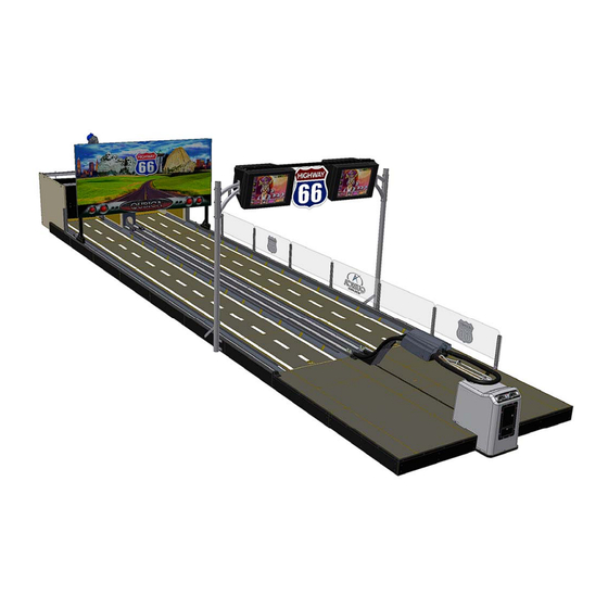
QubicaAMF Highway 66 User Manual (200 pages)
Brand:
QubicaAMF
| Category:
Sports & Outdoors
| Size: 22.36 MB
Table of Contents
Table of Contents
6
List of Figures
9
List of Procedures
10
Important Safety Instructions
11
Introduction to Highway 66
12
What Makes up the Highway 66 System
13
Identifying Your Highway 66 System Components
14
Understanding How the Game Is Played
15
About this Book
16
Safety Information
17
Highway 66 Fundamentals
19
Major Components and Assemblies
20
Ball Detector
20
Pit
20
Ball Elevator
20
Pinsetter
21
TMS Power Box
21
Pin Stabilizer
22
Main Motor
22
Drawbar
22
Solenoid/Opto Control Box
23
Pin Brakes
23
Optical Reading Devices
24
Ball Detector
24
Pin Detectors
24
Limit Optical Sensor (LOS)
24
Brake Optical Sensor (BOS)
24
Pin Pause Optical Sensor (PPOS)
24
Motor Encoder
24
Q-AMS Game Controller
25
Overhead Monitors
25
Understanding How the System Works
26
Pinsetter Cycles
27
Part Set
27
Full Set
27
Setting Up/Operating Your Highway 66
29
Getting Ready to Play
30
TMS Power Box DIP Switches
31
SW1-1 Jumping Ball (V1.16)
31
SW1-2 Control Mode (V1.00)
31
Figure 2-1 Dip Switch Location
31
(SW1-3,4,5) Pin Detection Sensitivity
32
SW1-6 Stabilizing Pause Time (V1.00)
32
SW1-7, 8 Pin Reading Pause Time (V1.00)
32
SW2-1, 2 Untangle Routine Type (V1.00)
33
SW2-3 Pinsetters Reaction after Power Failure (V1.16)
33
SW2-4 Pin Position When Pinsetters Are off (V1.00)
34
SW2-5 Pinsetter Reaction on Gutter Ball (V1.00)
34
SW2-6 Type of Game (V1.00)
34
SW2-7 Number Pins Installed (V1.11)
34
Procedures and Adjustments
35
Figure 2-2 Ball Detector
35
Procedure 2-1 - Ball Detector
35
Figure 2-3 Pin Detector Button
36
Figure 2-4 Reel Arm Position
36
Procedure 2-2 - Strings Adjustment
36
Figure 2-5 - Optical Sensor Position
37
Procedure 2-3 - LOS Limit Optical Sensor
37
Procedure 2-4 - BOS Brake Optical Sensor
37
Procedure 2-5 - PPOS Pin Pause Optical Sensor
37
Figure 2-6 - String Repair
38
Procedure 2-6 - Repairing String and Bushing
38
Figure 2-7 - Pin Brake Adjustment
39
Procedure 2-7 - Adjusting the Pin Brakes
39
Procedure 2-8 - Pin Brake Adjustment
39
Figure 2-8 - Drawbar Chain Adjustment
40
Procedure 2-9 - Adjusting Chain Tension of the Drawbar
40
Figure 2-9 Adjusting Rear Ball Lift V-Belt
41
Procedure 2-10 - Adjusting Rear Ball Lift V-Belt
41
Taking Care of Your Highway 66
43
Preventive Maintenance Basics
44
Manufacturer's Recommendations
44
Setting up a Preventive Maintenance Program
44
Getting Organized
45
Daily Maintenance Schedule
48
Weekly Maintenance Schedule
49
Monthly Maintenance Schedule
50
Quarterly and Annual Maintenance Schedule
51
Annual Inspection
52
Solving Problems
53
Read this First
54
Hint on Cabling Problems
54
Procedure 4-1 - Untangling Pin String
55
The Pinsetter Doesn't React to a Ball Rolled down the Lane
55
The Pinsetter Cycles When It Shouldn't
55
The Drawbar Continuously Moves Back and Forth
55
The Drawbar Does Not Attain the Rear of the Pinsetter
55
The Chains Emit a Loud Noise
55
One or more Fallen Pins Are Re-Spotted When They Are Not Supposed to
56
There Are no Pictures on the Monitors
56
There Is no Reaction from the Joystick
56
There Is no Reaction from the Machines
56
Wiring Diagrams
57
General Wiring
58
Power Box Wiring
59
Electronics Wiring
60
Joystick Diagram
61
Coin Mechanism (Coin Comparator)
62
Coin Mechanism (Multi Coin)
63
Pin out DB 25 Ctrl I/O
64
Joystick Control Cable
65
Power Box Connectors
66
Q-AMS Connectors
67
I/O Controller Connectors
68
Parts Listing
69
Safety Covers
70
Bowling Pin Highway
72
Main Components
74
Frame Assembly
76
Drawbar Assembly
78
DC Motor Assembly
81
9122015 Drawbar Shaft Assembly
82
9122027 Reel Arm Assembly
84
9122057 Pulley Detection Assembly
86
9122070 Pin Brake Assembly
88
9122220 Ten Pins Brakes Assembly
90
SB-043-01 Pulley Assembly
92
9166005 Table and Stabilization Assembly (ME-B03)
94
M-0701-25 Rear Ball Lift
96
SB-0701-30 Rear Ball Lift Assembly
100
SB-0540-75 Pit Cushion Assembly
102
Ball Rack Assembly
105
Ball Rack Hood Assembly
107
Monitors and Supports Assembly
109
LCD Supports Assembly
111
Q100-4500 Masking Unit
112
Q100-4150 ONE/TWO Ball Light
114
Q100-4156 Stop/Go LED
116
Fluorescent Support 115 Vac
119
Fluorescent Support 220 Vac
121
Q200-1010-00 Lateral Safety Guard
123
Electronic Components
124
SB-9802200-230 Power Box
126
Power Box Front Panel
128
Parts Number Index
130
Advertisement
Advertisement
Related Products
QubicaAMF 612-051-102
QubicaAMF 612-051-102BT
QubicaAMF 612-051-001
QubicaAMF 90XLi
QubicaAMF BES
QubicaAMF BES X
QubicaAMF Bowler Entertainment System
QubicaAMF CenterPunch
QubicaAMF EasyKey
QubicaAMF Harmony
QubicaAMF Categories
Sports & Outdoors
Video Gaming Accessories
Security Sensors
Accessories
Cleaning Equipment
More QubicaAMF Manuals
Login
Sign In
OR
Sign in with Facebook
Sign in with Google
Upload manual
Upload from disk
Upload from URL