
Subscribe to Our Youtube Channel
Related Manuals for Daikin LREN8A7Y1B


Summary of Contents for Daikin LREN8A7Y1B
- Page 1 Installation and operation manual CO₂ ZEAS outdoor unit and capacity up unit LREN8A7Y1B LREN10A7Y1B LREN12A7Y1B Installation and operation manual English CO₂ ZEAS outdoor unit and capacity up unit LRNUN5A7Y1...
- Page 2 (mm) 1500 ≥300 ≥500 ≥100 ≥500 ≥300 ≥500 ≥10 ≥50 ≥200 ≥300 ≥500 ≥100 ≥500 ≥300 ≥20 ≥100 ≥400 ≥10 ≥50 ≥200...
-
Page 3: Table Of Contents
Table of contents 13.1.3 Refrigerant piping length and height difference ... 21 Table of contents 13.1.4 To select the piping size ..........22 13.1.5 To select refrigerant branch kits........22 13.1.6 To select expansion valves for refrigeration ....22 1 About the documentation 13.2 Using stop valves and service ports........... -
Page 4: About The Documentation
WARNING Daikin website (publicly accessible). Fix the unit correctly. For instructions, see "12 Unit ▪ The full set of latest technical data is available on the Daikin installation" [ 4 16]. Business Portal (authentication required). WARNING Fixing method of the outdoor unit MUST be in accordance Specific installer safety with the instructions from this manual. - Page 5 2 Specific installer safety instructions WARNING WARNING In case of mechanical ventilation, take care the ventilated The unit contains small amounts of refrigerant R744. air is exhausted to the outdoor space and NOT into WARNING another closed area. Any gas or oil remaining inside the stop valve may blow off WARNING the spun piping.
- Page 6 2 Specific installer safety instructions WARNING WARNING Serious injury and/or damage can result from the blow-off Provide adequate measures to prevent that the unit can be of the liquid receiver safety valve (see "19.1 Piping used as a shelter by small animals. Small animals that unit" [ 4 46]): diagram: Outdoor make contact with electrical parts can cause malfunctions,...
-
Page 7: For The User
3 User safety instructions Configuration (see "16 Configuration" [ 4 38]) WARNING ▪ ONLY use R744 (CO ) as refrigerant. Other substances DANGER: RISK OF ELECTROCUTION may cause explosions and accidents. Commissioning (see "17 Commissioning" [ 4 40]) ▪ When installing, charging refrigerant, maintaining or performing service, ALWAYS use personal protective WARNING equipment, such as safety shoes, safety gloves and... -
Page 8: Instructions For Safe Operation
3 User safety instructions ▪ Do NOT sit, climb or stand on the (field supply). In order to be effective, unit. the unit must ALWAYS be electrically powered after installation. ▪ Units are marked with the following symbol: If for any reason the CO refrigerant leak detector is powered OFF, ALWAYS use a portable CO... - Page 9 3 User safety instructions Maintenance and service (see "6 Maintenance and CAUTION service" [ 4 10]) Before accessing terminal devices, DANGER: RISK OF make sure to interrupt all power supply. ELECTROCUTION refrigerant" [ 4 10]) About the refrigerant (see "6.1 About the To clean showcases or blower coils, stop operation and turn OFF all power WARNING supplies.
-
Page 10: About The System
4 About the system About the system Operation WARNING Operation modes Do NOT modify, disassemble, remove, reinstall or repair the unit yourself as incorrect dismantling or installation may The system allows for only one operation mode: refrigeration. cause an electrical shock or fire. Contact your dealer. Operation range NOTICE Do NOT use the system for other purposes. -
Page 11: Recommended Maintenance And Inspection
7 Troubleshooting WARNING Malfunction Measure Water (other than defrost water) leaks Stop the operation. ▪ Do NOT pierce or burn refrigerant cycle parts. from the unit. ▪ Be aware that the refrigerant inside the system is The operation switch does NOT work Turn OFF the power odourless. -
Page 12: Error Codes: Overview
8 Relocation Error codes: Overview Code Cause Solution Communication error Check the connection of For your reference, a list with malfunction codes is provided. In case between the capacity up the communication cables a malfunction code appears, contact your installer to inform him of unit and the outdoor unit. -
Page 13: To Handle The Outdoor Unit
10 About the box Outdoor unit Capacity up unit WARNING NOTICE Tear apart and throw away plastic packaging bags so that Use a belt sling that adequately bears the weight of the nobody, especially NOT children, can play with them. unit. -
Page 14: 11 About The Units And Options
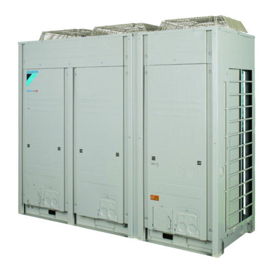
In this manual, we use the following names: WARNING General name Product name Outdoor unit LREN8A7Y1B LREN10A7Y1B Unit is charged and under high pressure. Set pressure of safety valve is 90 bar g. LREN12A7Y1B If refrigerant temperature is higher than 31°C... -
Page 15: System Layout
11 About the units and options The unit has some rest refrigerant inside when it leaves the factory. Text on card Translation To avoid the safety relief valve being opened, the unit must not be Cut off the lower part of the gas Cut off the lower part of the gas exposed to temperatures above 55°C. -
Page 16: Indoor Unit Constraints
12 Unit installation WARNING Fix the unit correctly. For instructions, see "12 Unit installation" [ 4 16]. NOTICE Adverse effects shall be considered. For example, danger of water collecting and freezing in discharge pipes for pressure relief devices, accumulation of dirt and debris, or blockage of the discharge pipes by solid CO (R744). -
Page 17: Additional Installation Site Requirements Of The Outdoor Unit In Cold Climates
12 Unit installation Calculate h1 and h2 as shown in the figure. Add h1/2 for To determine the minimum number of appropriate maintenance space to the front side. Add h2/2 for maintenance measures space to the back side (if wall height exceeds above values). For occupancies other than on the lowest underground floor of the building 12.1.2... -
Page 18: Opening And Closing The Unit
12 Unit installation QLAV QLMV 3 Remove the small front plates of each removed front panel. 2× 1× (If applicable) Small front plate left Small front plate right 100 150 200 250 300 350 600 650 700 750 800 850 900 950 1000 B (m³) Once the front plates open, the electrical component box can be accessed. -
Page 19: Mounting The Outdoor Unit
12 Unit installation Outdoor unit 1 Reinstall the small front plates of each removed front panel. 2× 1× (If applicable) Small front plate left Small front plate right 2 Reinstall the front panels. 4× Capacity up unit × × Outdoor unit Capacity up unit 3 Attach the small front plates to the front panels. -
Page 20: To Install The Outdoor Unit
13 Piping installation 12.3.2 To install the outdoor unit 1 Position the unit onto the installation structure. See also: (12.3 N·m) unit" [ 4 13]. "10.1.3 To handle the outdoor 2 Fix the unit onto the installation structure. See also "12.3.1 To structure" [ 4 19]. -
Page 21: Refrigerant Piping Material
13 Piping installation NOTICE Requirement Limit LREN* LREN* + The piping and other pressure-containing parts shall be LRNUN5* suitable for refrigerant and oil. Use K65 (or equivalent) copper-iron alloy tube system high-pressure Maximum Outdoor higher 35 m applications with a working pressure of 90 bar gauge at the height than indoor refrigeration side. -
Page 22: To Select The Piping Size
13 Piping installation Piping size between branching areas or between first and second branch Indoor unit Piping outer Piping material capacity index diameter size (kW) (mm) Liquid pipe for medium temperature and low temperature x≤3.0 Ø6.4×t0.8 C1220T–O 3.0<x≤10.0 Ø9.5×t0.65 K65 and equivalent piping 10.0<x≤18.0 Ø12.7×t0.85 K65 and equivalent piping... -
Page 23: Using Stop Valves And Service Ports
13 Piping installation 90° Evaporate temperature –10°C –35°C Liquid temperature 25°C 12°C Liquid pressure 6.8 MPa 6.8 MPa Refrigerant condition Subcooled liquid If capacity up unit is connected between outdoor unit and Result: The valve is fully open: showcases or blower coils Liquid temperature (at outlet of 15°C 4°C... -
Page 24: Connecting The Refrigerant Piping
13 Piping installation Valve cap Result: The service port is fully closed. To open the service port 1 Remove the service port cap with 2 spanners and remove the copper packing. 13.3 Connecting the refrigerant piping DANGER: RISK OF BURNING/SCALDING 13.3.1 To cut off the spun pipe ends When the product is shipped, a small amount of refrigerant gas is... -
Page 25: To Connect The Refrigerant Piping To The Outdoor Unit
13 Piping installation 6 Close stop valves CsV3 and CsV4 and service ports SP3, SP7 and SP11. 7 Connect the field piping to the cut pipes. 13.3.2 To connect the refrigerant piping to the outdoor unit WARNING ONLY connect the outdoor unit to showcases or blower coils with a design pressure: ▪... -
Page 26: Guidelines To Connect T-Joints
13 Piping installation 4× 13.3.3 Guidelines to connect T-joints INFORMATION Screw Piping joints and fittings shall comply with the requirements Side plate of EN 14276-2. 3 Dispose of the plate and its screws. 4 Remove the knockout in the bottom plate of the outdoor unit CAUTION and, if applicable, the one of the capacity up unit. -
Page 27: Guidelines To Install A Filter
13 Piping installation Where/how Install the dryer as near as possible to the WARNING outdoor unit. All installed safety valves MUST ventilate to the outdoor Install the dryer on the liquid pipe. space and NOT into a closed area. Install the dryer horizontally. CAUTION When brazing Follow the brazing instructions in the dryer... -
Page 28: About Changeover Valves
13 Piping installation Prerequisite: If you do not route the safety valve piping the same Maximum piping length way as the refrigerant piping, remove the other knockout (in the The allowed length of the safety valve piping is limited by the small front plate or the bottom plate of the outdoor unit). -
Page 29: Checking Refrigerant Piping: Setup
13 Piping installation 2 Vacuum the unit for at least 2 hours and to –100.7 kPaG 13.5.1 Checking refrigerant piping: Setup (-1.007 bar gauge) or below. 3 Leave the unit for more than 1 hour with a vacuum pressure of –100.7 kPaG (-1.007 bar gauge) or less. On the vacuum gauge, check if the pressure does not increase. -
Page 30: To Insulate The Gas Stop Valve
ONLY to a supply with a short-circuit power S greater than or equal to the minimum S value. Model Minimum S value LREN8A7Y1B – 5477 LREN10A7Y1B – 5819 ▪ Gently push the square against the tube to keep the square in place. -
Page 31: Field Wiring: Overview
14 Electrical installation 14.2 Field wiring: Overview X1M (A1P) X1M (A1P) X1M (A1P) X1M (A1P) L1 L2 L3 N C C1 W1 R P1 P2 C C1 W1 R P1 P2 L1 L2 L3 N IN/D UNIT OUT/D UNIT MULTI UNIT IN/D UNIT OUT/D UNIT MULTI UNIT... -
Page 32: Guidelines When Knocking Out Knockout Holes
14 Electrical installation 14.3 Guidelines when knocking out 14.4 Guidelines when connecting the knockout holes electrical wiring ▪ To punch a knockout hole in a front panel, hit on it with a hammer. Tightening torques ▪ To punch a knockout hole in the bottom panel, drill holes where indicated. -
Page 33: Connections To The Outdoor Unit
14 Electrical installation 14.6.1 Low voltage wiring – Outdoor unit Model Minimum circuit Recommended fuses ampacity Connections/routing/fixing LRNUN5A7Y1 16 A 25 A X1M (A1P) Power supply cable IN/D UNIT OUT/D UNIT MULTI UNIT LREN8* LREN10* LREN12* LRNUN5A7 F2 Q1 Q2 X1M (A1P) Voltage 380-415 V Current... -
Page 34: High Voltage Wiring - Outdoor Unit
14 Electrical installation Power supply: a: Power supply cable b: Overcurrent fuse c: Earth leakage circuit breaker Protective earth (screw) Output signals: d: Caution e: Warning f: Run g: Operation Factory-equipped operation switch: OFF: Unit operation turned OFF ON: Unit operation turned ON Remote: Unit controlled (ON/OFF) with remote operation switch Wiring remote operation switch:... -
Page 35: Connections To The Capacity Up Unit
14 Electrical installation Wiring Only use harmonised wire providing double insulation and suitable for the applicable voltage. 2-cord cable X1M (A1P) 0.75~1.25 mm² Maximum wiring length 130 m Details – Power supply components" [ 4 32]. "14.5 Specifications of standard wiring 14.7 Connections to the capacity up unit NOTICE ▪... -
Page 36: High Voltage Wiring - Capacity Up Unit
14 Electrical installation Details – Remote low noise switch: NOTICE Low noise switch. If you want to remotely turn ON/OFF low noise operation, you must install a low noise switch. Use a voltage-free contact for microcurrent (≤1 mA, 12 V DC). Low noise switch Mode Normal mode Low noise mode... -
Page 37: 15 Charging Refrigerant
15 Charging refrigerant 15.2 To determine the refrigerant Charging refrigerant amount 15.1 Precautions when charging INFORMATION refrigerant The capacity up unit is a pre-charged, closed circuit. There is no need to add additional refrigerant charging. WARNING 1 Calculate each amount of refrigerant for the liquid piping using ▪... -
Page 38: To Charge Refrigerant
16 Configuration Conversion ratio for indoor units: refrigeration Configuration Type Conversion ratio (kg/kW) DANGER: RISK OF ELECTROCUTION Low temperature Medium temperature Blower coil 0.059 INFORMATION Showcase 0.441 0.294 It is important that all information in this chapter is read sequentially by the installer and that the system is configured as applicable. -
Page 39: Field Setting Components
16 Configuration 16.1.3 Field setting components Capacity up unit installation With capacity up unit DIP switches Use DS1 to set the target evaporating temperature for the refrigeration side. Do NOT change DS2. Without capacity up unit If there is no electrical connection to the capacity up unit, an error Target evaporating code will be displayed on the outdoor unit. -
Page 40: To Set Field Settings
17 Commissioning 4 To change the value of the setting, push BS2 the same amount of times as the number of the value you need. For example: push 2 times for value 2. Result: The value appears on the 7-segment display. 5 Push BS3 1 time to validate the value change. -
Page 41: About The Test Run
17 Commissioning Field wiring Refrigerant charge Check that that the field wiring has been carried out The amount of refrigerant to be added to the unit shall be according to the instructions described in the chapter written in the logbook. installation" ... -
Page 42: Test Run Checks
17 Commissioning ▪ If communication is confirmed, the display will be OFF and Action Push button 7-segment display the compressors and fans start operating. Push BS2 a number The last 2 digits ▪ If communication is not confirmed, an error code will be of times, depending indicate the number BS1 BS2 BS3... -
Page 43: Troubleshooting
18 Troubleshooting Furthermore, you can add: Troubleshooting ▪ Instructions for shutting down the system in case of an emergency ▪ Name and address of fire department, police and hospital 18.1 Solving problems based on error ▪ Name, address and day and night telephone numbers for codes obtaining service If the unit runs into a problem, the user interface displays an error... - Page 44 18 Troubleshooting Main code LREN* LRNUN5* Cause Solution Malfunction of discharge/compressor body Check connection on PCB or actuator. temperature sensor For LREN*: ▪ (R31T) - A1P (X19A) ▪ (R32T) - A1P (X33A) ▪ (R33T) - A2P (X19A) ▪ (R91T) - A1P (X19A) ▪...
- Page 45 18 Troubleshooting Main code LREN* LRNUN5* Cause Solution ▪ Heat exchanger of outdoor unit is blocked. ▪ Check if any obstacles block the heat exchanger and remove them. ▪ The outdoor temperature is above the maximum operating temperature. ▪ Operate the unit only within the temperature operation range.
-
Page 46: 19 Technical Data
19 Technical data Technical data A subset of the latest technical data is available on the regional Daikin website (publicly accessible). The full set of latest technical data is available on the Daikin Business Portal (authentication required). 19.1 Piping diagram: Outdoor unit... -
Page 47: Piping Diagram: Capacity Up Unit
19 Technical data 19.2 Piping diagram: Capacity up unit 15.9 C1220T-H 15.9 C1220T-H Pressure sensor Plate heat exchanger Pressure switch Heat exchanger Check valve Oil separator Service port Liquid receiver Electronic expansion valve Distributor Filter Refrigerant pipe Propeller fan Oil and injection pipe Compressor with accumulator LREN8~12A7 + LRNUN5A7 Installation and operation manual... -
Page 48: Wiring Diagram: Outdoor Unit
19 Technical data 19.3 Wiring diagram: Outdoor unit The wiring diagram is delivered with the unit: F601U Fuse (A3P, A4P, A5P) ▪ For the outdoor unit: At the inside of the left electrical component Pilot lamp (service monitor-green) (A1P, box cover. A2P, A3P, A4P, A5P, A9P, A10P, A11P) Reactor (A3P) ▪... - Page 49 19 Technical data Capacity up unit Thermistor (M1C discharge) Notes: Thermistor (de-icer) This wiring diagram applies only to the capacity up unit. Thermistor (liquid separator outlet) Field wiring Thermistor (plate heat exchanger outlet) Terminal block Thermistor (liquid pipe) Connector Thermistor (M1C body) S1NPH High pressure sensor Terminal...
- Page 52 4P704141-1 B 0000000V 4P704141-1B 2022.12 Verantwortung für Energie und Umwelt...
Need help?
Do you have a question about the LREN8A7Y1B and is the answer not in the manual?
Questions and answers