
Related Manuals for Daikin LREN8A7Y1B


Summary of Contents for Daikin LREN8A7Y1B
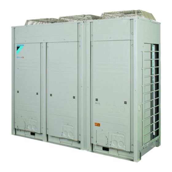
- Page 1 Installer and user reference guide CO₂ ZEAS outdoor unit and capacity up unit LREN8A7Y1B LREN10A7Y1B LREN12A7Y1B LRNUN5A7Y1...
-
Page 2: Table Of Contents
Table of contents Table of contents 1 About the documentation About this document ..............................2 General safety precautions About the documentation .............................. 2.1.1 Meaning of warnings and symbols ........................ For the installer ................................2.2.1 General ................................2.2.2 Installation site ............................... 2.2.3 Refrigerant —... - Page 3 Table of contents 14.1.2 Additional installation site requirements of the outdoor unit in cold climates..........60 14.1.3 Additional installation site requirements for CO₂ refrigerant ............... 60 14.2 Opening and closing the unit............................65 14.2.1 About opening the units..........................65 14.2.2 To open the outdoor unit..........................
- Page 4 Table of contents 17.6 To fix the refrigerant charge label ..........................121 18 Finishing the outdoor unit installation 18.1 To check the insulation resistance of the compressor ....................122 19 Configuration 19.1 Making field settings............................... 123 19.1.1 About making field settings..........................123 19.1.2 To access the field setting components......................
-
Page 5: About The Documentation
The original documentation is written in English. All other languages are translations. Technical engineering data ▪ A subset of the latest technical data is available on the regional Daikin website (publicly accessible). ▪ The full set of latest technical data is available on the Daikin Business Portal (authentication required). -
Page 6: General Safety Precautions
General safety precautions 2 General safety precautions 2.1 About the documentation ▪ The original documentation is written in English. All other languages are translations. ▪ The precautions described in this document cover very important topics, follow them carefully. ▪ The installation of the system, and all activities described in the installation manual and in the installer reference guide MUST be performed by an authorised installer. -
Page 7: For The Installer
WARNING Improper installation or attachment of equipment or accessories could result in electrical shock, short-circuit, leaks, fire or other damage to the equipment. ONLY use accessories, optional equipment and spare parts made or approved by Daikin unless otherwise specified. WARNING Make sure installation, testing and applied materials comply with applicable legislation (on top of the instructions described in the Daikin documentation). -
Page 8: Installation Site
General safety precautions CAUTION Wear adequate personal protective equipment (protective gloves, safety glasses,…) when installing, maintaining or servicing the system. CAUTION Do NOT touch the air inlet or aluminium fins of the unit. CAUTION ▪ Do NOT place any objects or equipment on top of the unit. ▪... - Page 9 WARNING Make sure installation, servicing, maintenance and repair comply with instructions from Daikin and with applicable legislation and are executed ONLY by authorised persons. WARNING If one or more rooms are connected to the unit using a duct system, make sure: ▪...
-
Page 10: Refrigerant - In Case Of R744
General safety precautions 2.2.3 Refrigerant — in case of R744 See the installation manual or installer reference guide of your application for more information. NOTICE Make sure refrigerant piping installation complies with applicable legislation. In Europe, EN378 is the applicable standard. NOTICE Make sure the field piping and connections are NOT subjected to stress. -
Page 11: Electrical
General safety precautions ▪ Only use R744 (CO ) as refrigerant. Other substances may cause explosions and accidents. ▪ Do NOT charge liquid refrigerant directly from a gas line. Liquid compression could cause compressor operation failure. ▪ Only use tools exclusively for the refrigerant type used in the system, this to ensure pressure resistance and prevent foreign materials from entering into the system. - Page 12 General safety precautions WARNING ▪ After finishing the electrical work, confirm that each electrical component and terminal inside the electrical components box is connected securely. ▪ Make sure all covers are closed before starting up the unit. CAUTION ▪ When connecting the power supply: connect the earth cable first, before making the current-carrying connections.
-
Page 13: Specific Installer Safety Instructions
WARNING Make sure installation, servicing, maintenance, repair and applied materials follow the instructions from Daikin (including all documents listed in “Documentation set”) and, in addition, comply with applicable legislation and are performed by qualified persons only. In Europe and areas where IEC standards apply, EN/IEC 60335-2-40 is the applicable standard. - Page 14 Specific installer safety instructions DANGER: RISK OF ELECTROCUTION Do NOT leave the unit unattended when the service cover is removed. WARNING Follow the service space dimensions in this manual for correct installation of the unit. "14.1.1 Installation site requirements of the outdoor unit" [ 57].
- Page 15 Specific installer safety instructions WARNING Install the unit ONLY in locations where the doors of the occupied space are NOT tight fitting. CAUTION Appliance NOT accessible to the general public, install it in a secured area, protected from easy access. The equipment meets the requirements for commercial and light-industrial locations when professionally installed and maintained.
- Page 16 Specific installer safety instructions WARNING NEVER remove the spun piping by brazing. Any gas or oil remaining inside the stop valve may blow off the spun piping. WARNING When stop valves are closed during service, the pressure of the closed circuit will increase due to high ambient temperature.
- Page 17 Specific installer safety instructions WARNING All installed safety valves MUST ventilate to the outdoor space and NOT into a closed area. WARNING Install safety valves in a proper way according to the applicable national regulation. WARNING To ensure that the safety valve(s) and the changeover valve are properly reinstalled, a leak test is mandatory.
- Page 18 Specific installer safety instructions WARNING Electrical wiring connection method MUST be in accordance with the instructions from: ▪ This manual. See "16 Electrical installation" [ 101]. ▪ The wiring diagram of the outdoor unit, which is delivered with the unit, located on the inside of the top plate. For a translation of its legend, see "25.4 ...
- Page 19 Specific installer safety instructions CAUTION This equipment is NOT intended for use in residential locations and will NOT guarantee to provide adequate protection to radio reception in such locations. Charging refrigerant (see "17 Charging refrigerant" [ 116]) WARNING Charging of refrigerant MUST be in accordance with the instructions from this manual.
- Page 20 Specific installer safety instructions DANGER: RISK OF BURNING/SCALDING WARNING Commissioning method MUST be in accordance with the instructions from this manual. See "20 Commissioning" [ 128]. CAUTION Do NOT perform the test operation while working on the indoor units. When performing the test operation, NOT ONLY the outdoor unit, but the connected indoor unit will operate as well.
- Page 21 Specific installer safety instructions "23 Troubleshooting" [ 139]) Troubleshooting (see DANGER: RISK OF ELECTROCUTION DANGER: RISK OF BURNING/SCALDING WARNING ▪ When carrying out an inspection on the switch box of the unit, ALWAYS make sure that the unit is disconnected from the mains. Turn off the respective circuit breaker.
-
Page 22: For The User
For the user LREN8~12A7 + LRNUN5A7 Installer and user reference guide CO₂ ZEAS outdoor unit and capacity up unit 4P704142-1 – 2022.08... -
Page 23: User Safety Instructions
User safety instructions 4 User safety instructions Always observe the following safety instructions and regulations. 4.1 General WARNING If you are NOT sure how to operate the unit, contact your installer. WARNING This appliance can be used by children aged from 8 years and above and persons with reduced physical, sensory or mental capabilities or lack of experience and knowledge if they have been given supervision or instruction concerning... -
Page 24: Instructions For Safe Operation
User safety instructions ▪ Units are marked with the following symbol: This means that electrical and electronic products may NOT be mixed with unsorted household waste. Do NOT try to dismantle the system yourself: dismantling the system, treatment of the refrigerant, of oil and of other parts MUST be done by an authorised installer and MUST comply with applicable legislation. - Page 25 User safety instructions WARNING NEVER use a flammable spray such as hair spray, lacquer or paint near the unit. It may cause a fire. CAUTION If this unit is installed indoors, it must ALWAYS be equipped with an electrically powered safety measure such as a CO refrigerant leak detector (field supply).
- Page 26 User safety instructions "5 About the system" [ 29]) About the system (see WARNING Do NOT modify, disassemble, remove, reinstall or repair the unit yourself as incorrect dismantling or installation may cause an electrical shock or fire. Contact your dealer. Maintenance and service (see "8 Maintenance and service" [ 33])
- Page 27 User safety instructions WARNING The R744 refrigerant (CO ) inside the unit is odourless, non-flammable and normally does NOT leak. If the unit is installed indoors, ALWAYS install a CO detector according to the specifications of standard EN378. If the refrigerant leaks in high concentrations in the room, it may have negative effects on its occupants such as asphyxiation and carbon dioxide poisoning.
- Page 28 User safety instructions "9 Troubleshooting" [ 35]) Troubleshooting (see WARNING Stop operation and shut OFF the power if anything unusual occurs (burning smells etc.). Leaving the unit running under such circumstances may cause breakage, electrical shock or fire. Contact your dealer. LREN8~12A7 + LRNUN5A7 Installer and user reference guide CO₂...
-
Page 29: About The System
About the system 5 About the system WARNING Do NOT modify, disassemble, remove, reinstall or repair the unit yourself as incorrect dismantling or installation may cause an electrical shock or fire. Contact your dealer. NOTICE Do NOT use the system for other purposes. In order to avoid any quality deterioration, do NOT use the unit for cooling precision instruments or works of art. -
Page 30: System Layout
About the system 5.1 System layout INFORMATION The following figure is an example and may NOT completely match your system layout a Main outdoor unit (LREN*) b Capacity up unit (LRNUN5*): only in combination with LREN12* c Safety valve (accessory bag) d Indoor unit for refrigeration (showcase) (field supply) e Indoor unit for refrigeration (blower coil) (field supply) f Safety valve (field supply) -
Page 31: Operation
Operation 6 Operation 6.1 Operation modes The system allows for only one operation mode: refrigeration. 6.2 Operation range Use the system in the following temperature ranges for safe and effective operation. Temperature type Temperature range Outdoor temperature –20~43°C DB Evaporation temperature Low temperature –40~–20°C DB Medium temperature –20~5°C DB... -
Page 32: Energy Saving And Optimum Operation
Energy saving and optimum operation 7 Energy saving and optimum operation Observe the following precautions to ensure the system operates properly. ▪ Adjust the room temperature properly for a comfortable environment. ▪ Adjust the evaporating temperature for refrigeration properly in the settings of the outdoor unit. -
Page 33: Maintenance And Service
Maintenance and service 8 Maintenance and service WARNING NEVER replace a fuse with a fuse of a wrong ampere ratings or other wires when a fuse blows out. Use of wire or copper wire may cause the unit to break down or cause a fire. -
Page 34: About The Refrigerant
Maintenance and service ▪ Clean the showcases and blower coils. Respect the maintenance tips and procedures for cleaning in the installation/operation manuals of the indoor units. ▪ Turn on the power at least 6 hours before operating the unit in order to ensure smoother operation. -
Page 35: Troubleshooting
Troubleshooting 9 Troubleshooting If system malfunctions are likely to degrade the articles in the room/showcase, you can ask your installer to install an alarm (example: lamp). For more information, contact your installer. If one of the following malfunctions occur, take the measures shown below and contact your dealer. -
Page 36: Error Codes: Overview
Troubleshooting Malfunction Measure The system operates but ▪ Check if air inlet or outlet of outdoor or indoor cooling is insufficient. unit is not blocked by obstacles. Remove any obstacles and make sure the air can flow freely. (for refrigerator and freezer indoor units) ▪... - Page 37 Troubleshooting Code Cause Solution Lost phase in power supply. Check the connection of the power supply cable. Insufficient supply voltage Check if the supply voltage is supplied properly. Communication error between Check the connection of the the capacity up unit and the communication cables upstream outdoor unit.
-
Page 38: Relocation
Relocation 10 Relocation Contact your dealer to remove and reinstall the entire unit. Moving units requires technical expertise. LREN8~12A7 + LRNUN5A7 Installer and user reference guide CO₂ ZEAS outdoor unit and capacity up unit 4P704142-1 – 2022.08... -
Page 39: Disposal
Disposal 11 Disposal NOTICE Do NOT try to dismantle the system yourself: dismantling of the system, treatment of the refrigerant, oil and other parts MUST comply with applicable legislation. Units MUST be treated at a specialised treatment facility for reuse, recycling and recovery. LREN8~12A7 + LRNUN5A7 Installer and user reference guide CO₂... -
Page 40: For The Installer
For the installer LREN8~12A7 + LRNUN5A7 Installer and user reference guide CO₂ ZEAS outdoor unit and capacity up unit 4P704142-1 – 2022.08... -
Page 41: About The Box
About the box 12 About the box Keep the following in mind: ▪ At delivery, the unit MUST be checked for damage and completeness. Any damage or missing parts MUST be reported immediately to the claims agent of the carrier. ▪... -
Page 42: To Unpack The Outdoor Unit
About the box 12.1.2 To unpack the outdoor unit 1 Remove the packaging material from the unit. Take care not to damage the unit when removing the shrink foil with a cutter. a Outdoor unit b Capacity up unit WARNING Tear apart and throw away plastic packaging bags so that nobody, especially NOT children, can play with them. -
Page 43: To Remove The Accessories From The Outdoor Unit
About the box Capacity up unit NOTICE Use a belt sling that adequately bears the weight of the unit. The width of the holes for belts in the outdoor unit is 90 mm. Also see the label about handling on the unit. 12.1.4 To remove the accessories from the outdoor unit Outdoor unit RXXX... - Page 44 About the box Capacity up unit a Declaration of conformity LREN8~12A7 + LRNUN5A7 Installer and user reference guide CO₂ ZEAS outdoor unit and capacity up unit 4P704142-1 – 2022.08...
-
Page 45: About The Units And Options
About the units and options 13 About the units and options In this chapter 13.1 Identification................................... 13.1.1 Identification label: Outdoor unit .......................... 13.2 About the outdoor unit ................................13.2.1 Labels on outdoor unit............................13.3 System layout..................................13.4 Combining units and options..............................13.4.1 Possible options for the outdoor unit........................ -
Page 46: About The Outdoor Unit
International Standard. General name and product name In this manual, we use the following names: General name Product name Outdoor unit LREN8A7Y1B LREN10A7Y1B LREN12A7Y1B Capacity up unit LRNUN5A7Y1 Temperature range Temperature type... -
Page 47: Labels On Outdoor Unit
About the units and options 13.2.1 Labels on outdoor unit Label about flow directions Label used for Text on label Translation The first two labels: from LRYEN10A7Y1 or From LRYEN10A7Y1 or LREN12A7Y1B to LREN12A7Y1B to Capacity up unit Refrigeration Refrigeration The third label: Gas from Refrigeration Gas from Refrigeration... - Page 48 About the units and options Text on warning label Translation Set pressure of safety valve is 90 bar g. Set pressure of safety valve is 90 bar g. If refrigerant temperature is higher than If refrigerant temperature is higher than 31°C there is a possibility that the safety 31°C there is a possibility that the safety valve will open during service or power valve will open during service or power...
- Page 49 About the units and options CAUTION WARNING ELECTRIC SHOCK CAUTION Caution when servicing the switch box 1. Before obtaining access to terminal devices, all supply circuits must be interrupted because units at standstill may be in a pre-heating mode and start automatically. 2.
- Page 50 About the units and options Text on warning label Translation 1. Before obtaining access to terminal 1. Before obtaining access to terminal devices, all supply circuits must be devices, all supply circuits must be interrupted because units at standstill interrupted because units at standstill may be in a pre-heating mode and start may be in a pre-heating mode and start automatically.
- Page 51 About the units and options Card on how to cut the spun pipe ends of the stop valve pipes Text on card Translation To cut off the spun pipe ends To cut off the spun pipe ends When the product is shipped, a small When the product is shipped, a small amount of refrigerant gas is kept inside amount of refrigerant gas is kept inside...
- Page 52 About the units and options Text on card Translation See Note. See Note. Cut off the lower part of the gas and Cut off the lower part of the gas and liquid stop valve pipes along the black liquid stop valve pipes along the black line.
-
Page 53: System Layout
About the units and options 13.3 System layout INFORMATION The following figure is an example and may NOT completely match your system layout a Main outdoor unit (LREN*) b Capacity up unit (LRNUN5*): only in combination with LREN12* c Safety valve (accessory bag) d Indoor unit for refrigeration (showcase) (field supply) e Indoor unit for refrigeration (blower coil) (field supply) f Safety valve (field supply) -
Page 54: Indoor Unit Constraints
About the units and options Communication box (BRR9B1V1) Install the modbus communication box to fully integrate your system with building control automation networks and other monitoring systems. 13.5 Indoor unit constraints WARNING ONLY the refrigeration parts that are also designed to work with R744 (CO ) shall be connected to the system. - Page 55 About the units and options Restriction Usage range or value Maximum height difference outdoor 5 m unit above indoor unit Maximum height difference outdoor 10 m unit below indoor unit Field setting components "DIP switches" [ 124] LREN8~12A7 + LRNUN5A7 Installer and user reference guide CO₂...
-
Page 56: Unit Installation
Unit installation 14 Unit installation WARNING ▪ Install all necessary countermeasures in case of refrigerant leakage according to standard EN378 (see "14.1.3 Additional installation site requirements for CO₂ refrigerant" [ 60]). ▪ Install a CO leak detector (field supply) in every room with refrigerant piping, showcases or blower coils, and - if present - enable the function for refrigerant leak detection (see the installation manual of the indoor units). -
Page 57: Installation Site Requirements Of The Outdoor Unit
Unit installation 14.1.1 Installation site requirements of the outdoor unit CAUTION Appliance NOT accessible to the general public, install it in a secured area, protected from easy access. The equipment meets the requirements for commercial and light-industrial locations when professionally installed and maintained. CAUTION This equipment is NOT intended for use in residential locations and will NOT guarantee to provide adequate protection to radio reception in such locations. - Page 58 Unit installation ▪ When installing the unit in a small room, take measures in order to keep the refrigerant concentration from exceeding allowable safety limits in the event of a refrigerant leak. "14.1.3 Additional installation site requirements for CO₂ refrigerant" [ 60]. ▪...
- Page 59 Unit installation NOTICE The equipment described in this manual may cause electronic noise generated from radio-frequency energy. The equipment complies to specifications that are designed to provide reasonable protection against such interference. However, there is no guarantee that interference will not occur in a particular installation. It is therefore recommended to install the equipment and electric wires in such a way that they keep a proper distance from stereo equipment, personal computers, etc.
-
Page 60: Additional Installation Site Requirements Of The Outdoor Unit In Cold Climates
Unit installation ▪ In places where a mineral oil mist, spray or vapour may be present in the atmosphere. Plastic parts may deteriorate and fall off or cause water leakage. It is NOT recommended to install the unit in the following places because it may shorten the life of the unit: ▪... - Page 61 Unit installation Allowable refrigerant charge The calculation of the allowable refrigerant charge depends on the combination of the "access category" and the "location classification" as described in the following table. INFORMATION Where the possibility exists of more than one access category, the more stringent requirements apply.
- Page 62 Unit installation Access category Description Examples Authorized access Rooms, parts of buildings, buildings Manufacturing facilities, e.g. for chemicals, where only authorized persons have food, beverage, ice, ice cream, refineries, access, who are acquainted with cold stores, dairies, abattoirs, non-public general and special safety precautions areas in supermarkets.
- Page 63 Unit installation To determine the minimum number of appropriate measures For occupancies other than on the lowest underground floor of the building If the total refrigerant charge (kg) …the number of appropriate measures divided by the room volume ) is… must be at least…...
- Page 64 Unit installation QLAV QLMV 100 150 200 250 300 350 600 650 700 750 800 850 900 950 1000 B (m³) 14‒2 Example graph for calculation A Refrigerant charge limit B Room volume a Installation is not allowed b 2 appropriate measures required c 1 appropriate measure required d No measure required INFORMATION...
-
Page 65: Opening And Closing The Unit
Unit installation ▪ Where an indoor unit, or any related refrigerant-containing pipework, is located in a space where the total charge exceeds the allowable charge, make special provisions to ensure at least an equivalent level of safety. 14.2 Opening and closing the unit 14.2.1 About opening the units At certain times, you have to open the unit. -
Page 66: To Open The Electrical Component Box Of The Outdoor Unit
Unit installation 4× × a Outdoor unit b Capacity up unit 3 Remove the small front plates of each removed front panel. 2× 1× a (If applicable) Small front plate left b Small front plate right Once the front plates open, the electrical component box can be accessed. See "14.2.3 To open the electrical component box of the outdoor unit" [ 66]. -
Page 67: To Close The Outdoor Unit
Unit installation Electrical component box of the capacity up unit 4× 14.2.4 To close the outdoor unit NOTICE When closing the outdoor unit cover, make sure that the tightening torque does NOT exceed 3.98 N•m. 1 Reinstall the small front plates of each removed front panel. 2×... -
Page 68: Mounting The Outdoor Unit
Unit installation b Capacity up unit 14.3 Mounting the outdoor unit 14.3.1 About mounting the outdoor unit Typical workflow Mounting the outdoor unit typically consists of the following stages: Providing the installation structure. Installing the outdoor unit. 14.3.2 Precautions when mounting the outdoor unit INFORMATION Also read the precautions and requirements in the following chapters: ▪... - Page 69 Unit installation Outdoor unit Capacity up unit ▪ The preferred installation is on a solid longitudinal foundation (steel beam frame or concrete). The foundation must be larger than the grey marked area. ≥765 ≥765 (mm) Minimum foundation 1 LREN* 2 LRNUN5* LREN8~12A7 + LRNUN5A7 Installer and user reference guide CO₂...
-
Page 70: To Install The Outdoor Unit
Unit installation Unit LREN* 1940 1102 LRNUN5* — 14.3.4 To install the outdoor unit 1 Position the unit onto the installation structure. See also: "12.1.3 To handle the outdoor unit" [ 42]. 2 Fix the unit onto the installation structure. See also "14.3.3 ... -
Page 71: To Provide Drainage
Unit installation (12.3 N·m) 14.3.6 To provide drainage Make sure that condensation water can be evacuated properly. NOTICE Prepare a water drainage channel around the foundation to drain waste water from around the unit. When the outdoor temperatures are negative, the drained water from the outdoor unit will freeze up. -
Page 72: Piping Installation
Piping installation 15 Piping installation In this chapter 15.1 Preparing refrigerant piping ..............................15.1.1 Refrigerant piping requirements ........................... 15.1.2 Refrigerant piping material ............................ 15.1.3 Refrigerant piping length and height difference ....................15.1.4 To select the piping size ............................15.1.5 To select refrigerant branch kits..........................15.1.6 To select expansion valves for refrigeration...................... -
Page 73: Refrigerant Piping Material
Piping installation NOTICE Foreign materials inside pipes are NOT allowed (including oils for fabrication). NOTICE The piping and other pressure-containing parts shall be suitable for refrigerant and oil. Use K65 (or equivalent) copper-iron alloy tube system for high-pressure applications with a working pressure of 90 bar gauge at the refrigeration side. NOTICE NEVER use standard hoses and manometers. - Page 74 Piping installation Requirement Limit LREN* LREN* + LRNUN5* Piping length between LREN* and Not specified, but piping must be LRNUN5* horizontal Maximum branch piping length ▪ Example refrigeration side: 50 m C+D+(E or F) c+d+(e or f) Maximum total piping length 180 m Maximum height Outdoor higher...
-
Page 75: To Select The Piping Size
Piping installation a Refrigeration indoor unit b Flow direction in refrigerant suction piping To install riser piping If the outdoor unit is installed lower than the refrigeration indoor unit, install riser piping close to the indoor unit. When the compressor of the outdoor unit starts, correctly installed riser piping will prevent liquid from flowing back to the outdoor unit. - Page 76 Piping installation 3 Indoor unit (showcase) 4 Indoor unit (blower coil) A~J Liquid piping a~g Gas piping H1~H3 Height difference In case the required pipe sizes (inch sizes) are not available, it is also allowed to use other diameters (mm sizes), taken the following into account: ▪...
-
Page 77: To Select Refrigerant Branch Kits
Piping installation Piping size from branch to indoor unit Liquid and gas piping: outer diameter size Same size as C, D, c, d. If piping sizes of the indoor units are different, connect a reducer close to the indoor unit to align piping sizes. Piping from branch to indoor unit (C, D, E;... -
Page 78: Using Stop Valves And Service Ports
Piping installation A Liquid piping (refrigeration side): 90 bar gauge B Gas piping (refrigeration side): depends on design pressure of showcase and blower coil. For example, 60 bar gauge 1 Capacity up unit (LRNUN5*) 2 Outdoor unit (LREN* ) 3 Indoor unit (showcase) 4 Indoor unit (blower coil) 15.2 Using stop valves and service ports WARNING... -
Page 79: Overview Stop Valves And Service Ports For Connection And Charging
Piping installation 15.2.1 Overview stop valves and service ports for connection and charging a Gas stop valve CsV3 b Liquid stop valve CsV4 c Service port SP10 (gas side) d Service port SP3 (gas side) e Service port SP7 (liquid side) f Service port SP11 (gas side) g Service port SP8 (gas side) 15.2.2 Overview stop valves for maintenance... -
Page 80: To Handle The Stop Valve
Piping installation a Stop valve b Stop valve 15.2.3 To handle the stop valve Take the following guidelines into account: ▪ The gas and liquid stop valves are factory closed. ▪ Make sure to keep all stop valves open during operation. ▪... -
Page 81: Tightening Torques
Piping installation c Field piping connection 15‒2 Ball stop valve: intersection a Stop valve cap b Ball + stem and handle To open the stop valve 1 Remove the valve cap. 2 Turn counterclockwise to open the valve. 90° Result: The valve is fully open: a To outdoor unit b To indoor unit To close the stop valve... - Page 82 Piping installation ▪ All service ports are of the backseat type and do not have a valve core. ▪ After handling the service port, make sure to tighten the service port cap and the valve cap securely. ▪ Check for refrigerant leaks after tightening the service port cap and the valve cap.
-
Page 83: Connecting The Refrigerant Piping
Piping installation 4 Apply screw lock agent or silicon sealant to the screw thread when mounting the service port cap. Without it, moisture and condensing water may penetrate and freeze between the screw thread. As a result, refrigerant may leak and the service port cap may break. a New copper packing b Screw lock agent or silicon sealant only on screw thread 5 Tighten the service port cap with 2 spanners. -
Page 84: Precautions When Connecting The Refrigerant Piping
Piping installation 15.3.2 Precautions when connecting the refrigerant piping INFORMATION Also read the precautions and requirements in the following chapters: ▪ "2 General safety precautions" [ 6] ▪ "15.1 Preparing refrigerant piping" [ 72] DANGER: RISK OF BURNING/SCALDING CAUTION NEVER bend high pressure piping! Bending can reduce the pipe thickness and thus weaken the piping. -
Page 85: To Cut Off The Spun Pipe Ends
Piping installation 15.3.3 To cut off the spun pipe ends When the product is shipped, a small amount of refrigerant gas is kept inside the product. Therefore, the pipes contain a pressure higher than the atmospheric pressure. For safety reasons, it is necessary to release the refrigerant before cutting the spun pipe ends. -
Page 86: To Connect The Refrigerant Piping To The Outdoor Unit
Piping installation 15.3.4 To connect the refrigerant piping to the outdoor unit WARNING ONLY connect the outdoor unit to showcases or blower coils with a design pressure: ▪ At the high pressure side (liquid side) of 90 bar gauge. ▪ At the low pressure side (gas side) of 60 bar gauge (is possible with safety valve at field gas piping). - Page 87 Piping installation 2 Remove the knockout in the small front plate of the outdoor unit and, if applicable, the one of the capacity up unit. For more information, see "16.3 Guidelines when knocking out knockout holes" [ 106]. 3 Cut off the spun pipe ends. See "15.3.3 To cut off the spun pipe ends" [ 85].
- Page 88 Piping installation 1 Remove the left front panel of the outdoor unit and, if applicable, the one of the capacity up unit. See "14.2.2 To open the outdoor unit" [ 65]. 2 Unscrew the 4 screws to remove the side plate of the outdoor unit. 4×...
-
Page 89: To Braze The Pipe End
Piping installation 15.3.5 To braze the pipe end General guidelines ▪ When brazing, blow through with nitrogen to prevent creation of large quantities of oxidized film on the inside of the piping. This film adversely affects valves and compressors in the refrigerating system and prevents proper operation. ▪... - Page 90 Piping installation a Correct heating zone b Heating zone is too large. Brazing material can cause obstructions inside the piping. A running test might detect these obstructions. c Heating zone is too small. The brazed connection will not be strong and might rip. 80~85˚...
-
Page 91: Guidelines To Connect T-Joints
Piping installation 90˚ a Brazing rod 15.3.6 Guidelines to connect T-joints INFORMATION Piping joints and fittings shall comply with the requirements of EN 14276-2. CAUTION ALWAYS use K65 T-joints for refrigerant branching. K65 T-joints are field supplied. Liquid piping Always branch horizontally when connecting the branch piping. To prevent uneven refrigerant flow, always branch downwards when using a header. -
Page 92: Guidelines To Install A Dryer
Piping installation 15.3.7 Guidelines to install a dryer NOTICE Do NOT operate the unit without a dryer installed on the liquid pipe. Possible consequence: Without dryer, operating the unit may cause a choked expansion valve, hydrolysis of the refrigerant oil and copper plating of the compressor. Install a dryer on the liquid piping: Dryer type Drops of R744 water capacity at 60°C: 200... -
Page 93: About Safety Valves
Piping installation 15.3.9 About safety valves When installing a safety valve, always keep the design pressure of the circuit in mind. See "6 Operation" [ 31]. WARNING Serious injury and/or damage can result from the blow-off of the liquid receiver safety valve (see "25.2 Piping diagram: Outdoor unit" [ 148]):... - Page 94 Piping installation Accessories The safety valve is part of the accessories. As the safety valve is threaded, it cannot be brazen onto the field piping. Therefore, the accessory bag also contains a threaded piece that acts as an intermediate between the field piping and the safety valve.
- Page 95 Piping installation 6 It is recommended to apply 20 PTFE tape windings onto the thread of the threaded piece. 7 It is recommended to screw the safety valve onto the threaded piece and tighten it between 35 and 60 N•m. The safety valve has to be installed vertically so water cannot enter the blow-off hole.
-
Page 96: Guidelines To Install Blow-Off Piping
Piping installation Changeover Maximum piping length (m) for Ø 22.2 valve's kV value elbows elbows elbows elbows elbows 3-3,49 3,5-4,49 4,5-4,99 5-7,99 K65 or equivalent piping 0 = There is no changeover valve present Specifications safety valve Flow area Connection Allowable temperature range 90 bar... -
Page 97: About Checking The Refrigerant Piping
Piping installation 15.4.1 About checking the refrigerant piping 15.4.2 Checking refrigerant piping: General guidelines Connect the vacuum pump through a manifold to the service port of all stop valves to increase efficiency (refer to "15.4.3 Checking refrigerant piping: Setup" [ 97]). NOTICE Use a 2-stage vacuum pump with a non-return valve or a solenoid valve that can evacuate to a gauge pressure of –... -
Page 98: To Perform A Strength Pressure Test And Leak Test
Piping installation NOTICE The connections to the indoor units and all indoor units should also be leak and vacuum tested. Keep any possible (field supplied) field piping valves open as well. Also see the indoor unit installation manual for more details. Leak test and vacuum drying should be done before the power supply is set to the unit. -
Page 99: Insulating The Refrigerant Piping
Piping installation 2 Afterwards, vacuum dry the unit to –100.7 kPaG (-1.007 bar gauge) or less for at least 1 hour. 3 Repeat vacuum destruction and vacuum drying if the pressure does not reach –100.7 kPaG (-1.007 bar gauge) or less. 4 Leave the unit for more than 1 hour with a vacuum pressure of –100.7 kPaG (-1.007 bar gauge) or less. - Page 100 Piping installation ▪ Remove the protective tape from between the sealing to reveal the sticky side. ▪ Gently push both sides of the sealing together to close the insulation. 2 Install the accessory insulation square around the gas stop valve's cap. ▪...
-
Page 101: Electrical Installation
Electrical installation 16 Electrical installation CAUTION This equipment is NOT intended for use in residential locations and will NOT guarantee to provide adequate protection to radio reception in such locations. NOTICE If the equipment is installed closer than 30 m to a residential location, the professional installer MUST evaluate the EMC situation before installation. -
Page 102: Guidelines When Connecting The Electrical Wiring
Electrical installation 16.1.2 Guidelines when connecting the electrical wiring Keep the following in mind: NOTICE We recommend using solid (single-core) wires. If stranded wires are used, slightly twist the strands to consolidate the end of the conductor for either direct use in the terminal clamp or insertion in a round crimp-style terminal. - Page 103 Electrical installation Use the following methods for installing wires: Wire type Installation method Single-core wire AA´ A´ Stranded conductor wire twisted to "solid-like" connection a Curled wire (single-core or twisted stranded conductor wire) b Screw c Flat washer Stranded conductor wire with round crimp-style terminal a Terminal...
-
Page 104: About Electrical Compliance
ONLY to a supply with a short-circuit power S greater than or equal to the minimum S value. Model Minimum S value LREN8A7Y1B – 5477 LREN10A7Y1B – 5819 LREN12A7Y1B –... -
Page 105: Field Wiring: Overview
Electrical installation 16.2 Field wiring: Overview X1M (A1P) X1M (A1P) X1M (A1P) X1M (A1P) C C1 W1 R P1 P2 C C1 W1 R P1 P2 L1 L2 L3 N L1 L2 L3 N IN/D UNIT OUT/D UNIT MULTI UNIT IN/D UNIT OUT/D UNIT MULTI UNIT... -
Page 106: Guidelines When Knocking Out Knockout Holes
Electrical installation 16.3 Guidelines when knocking out knockout holes ▪ To punch a knockout hole in a front panel, hit on it with a hammer. ▪ To punch a knockout hole in the bottom panel, drill holes where indicated. ▪ After knocking out the holes, we recommend removing any burrs and paint the edges and areas around the holes using repair paint to prevent rusting. -
Page 107: Specifications Of Standard Wiring Components
Electrical installation WARNING Provide adequate measures to prevent that the unit can be used as a shelter by small animals. Small animals that make contact with electrical parts can cause malfunctions, smoke or fire. 16.4 Specifications of standard wiring components Power supply NOTICE When using residual current operated circuit breakers, be sure to use a high-speed... -
Page 108: Connections To The Outdoor Unit
Electrical installation Remote switches See details in: ▪ "16.5.1 Low voltage wiring – Outdoor unit" [ 108] ▪ "16.6.1 Low voltage wiring – Capacity up unit" [ 112] Output signals See details in: ▪ "16.5.2 High voltage wiring – Outdoor unit" [ 110] ▪ "16.6.2 High voltage wiring – Capacity up unit" [ 114] 16.5 Connections to the outdoor unit... - Page 109 Electrical installation X1M (A1P) e Wiring intake (knockout hole) for low voltage. See "16.3 Guidelines when knocking out knockout holes" [ 106]. Details – DIII transmission wiring "16.4 Specifications of standard wiring components" [ 107]. Details – Remote operation switch NOTICE Remote operation switch. The unit is factory-equipped with an operation switch with which you can turn unit operation ON/OFF.
-
Page 110: High Voltage Wiring - Outdoor Unit
Electrical installation Details – Remote low noise switch NOTICE Low noise switch. If you want to remotely turn ON/OFF low noise operation, you must install a low noise switch. Use a voltage-free contact for microcurrent (≤1 mA, 12 V DC). Low noise switch Mode Normal mode Low noise mode... - Page 111 Electrical installation h Wiring intake (knockout hole) for high voltage. See "16.3 Guidelines when knocking out knockout holes" [ 106]. Details – Output signals NOTICE Output signals. The outdoor unit is provided with a terminal (X4M class II construction) that can output 4 different signals. The signal is 220~240 V AC. The maximum load for all signals is 0.5 ...
-
Page 112: Connections To The Capacity Up Unit
Electrical installation 16.6 Connections to the capacity up unit NOTICE ▪ Be sure to keep the power line and transmission line apart from each other (≥50 mm). Transmission wiring and power supply wiring may cross, but may not run parallel. ▪ Transmission wiring and power supply wiring may NOT touch internal piping in order to avoid wire damage due to high temperature piping. - Page 113 Electrical installation Details – DIII transmission wiring "16.4 Specifications of standard wiring components" [ 107]. Details – Remote operation switch NOTICE Remote operation switch. The unit is factory-equipped with an operation switch with which you can turn unit operation ON/OFF. If you want to remotely turn ON/ OFF operation of the capacity up unit, a remote operation switch is required.
-
Page 114: High Voltage Wiring - Capacity Up Unit
Electrical installation Maximum wiring length 130 m 16.6.2 High voltage wiring – Capacity up unit Connections/routing/fixing L1 L2 L3 L1 L2 L3 N 3N~ 50 Hz 380-415 V C C1 W1 R P1 P2 a d/e/f X1M Power supply: a: Power supply cable b: Overcurrent fuse c: Earth leakage circuit breaker PE Protective earth (screw) - Page 115 Electrical installation Details – Output signals NOTICE Output signals. The outdoor unit is provided with a terminal (X2M class II construction) that can output 3 different signals. The signal is 220~240 V AC. The maximum load for all signals is 0.5 A. The unit outputs a signal in the following situations: ▪...
-
Page 116: Charging Refrigerant
Charging refrigerant 17 Charging refrigerant In this chapter 17.1 About charging refrigerant..............................116 17.2 Precautions when charging refrigerant ..........................116 17.3 About the refrigerant ................................117 17.4 To determine the refrigerant amount ........................... 119 17.5 To charge refrigerant................................120 17.6 To fix the refrigerant charge label............................ -
Page 117: About The Refrigerant
Charging refrigerant CAUTION Do NOT charge liquid refrigerant directly from a gas line. Liquid compression could cause compressor operation failure. NOTICE If the power of some units is turned off, the charging procedure cannot be finished properly. NOTICE Only when charging the unit for the first time, turn ON the power 6 hours before operation in order to have power running to the crankcase heater and to protect the compressor. - Page 118 Charging refrigerant WARNING ▪ Do NOT pierce or burn refrigerant cycle parts. ▪ Be aware that the refrigerant inside the system is odourless. WARNING The R744 refrigerant (CO ) inside the unit is odourless, non-flammable and normally does NOT leak. If the unit is installed indoors, ALWAYS install a CO detector according to the specifications of standard EN378.
-
Page 119: To Determine The Refrigerant Amount
Charging refrigerant 17.4 To determine the refrigerant amount INFORMATION The capacity up unit is a pre-charged, closed circuit. There is no need to add additional refrigerant charging. 1 Calculate each amount of refrigerant for the liquid piping using the Calculation table in this chapter, based on the piping size and length: (a) (b) (c) and (d). -
Page 120: To Charge Refrigerant
Charging refrigerant Type of indoor unit Total amount of refrigerant (kg) Blower coils Showcases Subtotal (e)+(f): Required amount of refrigerant for outdoor unit (kg): 18.4[3] 18.4 kg Subtotal [1]+[2]+[3] (kg) Additional amount of refrigerant charged when test run if required (kg) Total amount of refrigerant [4]+[5] (kg) The maximum amount of additional refrigerant that can be charged at the time of the test run is 10% of the amount of refrigerant as calculated from the capacity of connected indoor units. -
Page 121: To Fix The Refrigerant Charge Label
Charging refrigerant 4 When the refrigerant is charged, fully open all gas and liquid stop valves. WARNING After charging refrigerant, keep the power supply and operation switch of the outdoor unit ON to avoid a pressure increase on the low pressure (suction piping) side and to avoid pressure increase on the pressure side of the liquid receiver. -
Page 122: Finishing The Outdoor Unit Installation
Finishing the outdoor unit installation 18 Finishing the outdoor unit installation 18.1 To check the insulation resistance of the compressor NOTICE If, after installation, refrigerant accumulates in the compressor, the insulation resistance over the poles can drop, but if it is at least 1 MΩ, then the unit will not break down. -
Page 123: Configuration
Configuration 19 Configuration DANGER: RISK OF ELECTROCUTION INFORMATION It is important that all information in this chapter is read sequentially by the installer and that the system is configured as applicable. In this chapter 19.1 Making field settings................................123 19.1.1 About making field settings ........................... -
Page 124: Field Setting Components
Configuration a Outdoor unit b Capacity up unit c1 Inspection hole c2 Inspection hole cover d Operation switch (S1S) e Field setting components e1 7‑segment displays: ON ( ) OFF ( ) Flashing ( e2 Push buttons: BS1: MODE: For changing the set mode BS2: SET: For field setting BS3: RETURN: For field setting e3 DIP switches... - Page 125 Configuration Target evaporating temperature –30°C –35°C –40°C Factory setting Use DS2 to define a system layout with or without capacity up unit. NOTICE When installing a capacity up unit it is mandatory to put switch 4 ON. If DS2 is not set correctly, the capacity up unit will NOT operate and no error code is displayed on the PCB of the outdoor unit.
-
Page 126: To Access Mode 1 Or 2
Configuration Description Setting 8 (in mode 2) Value 4 (in mode 2) 19.1.4 To access mode 1 or 2 After the units are turned ON, the display goes to its default situation. From there, you can access mode 1 and mode 2. Initialisation: default situation NOTICE Turn ON the power 6 hours before operation in order to have power running to the... -
Page 127: To Set Field Settings
Configuration 19.1.5 To set field settings Prerequisite: Start from the default setting in the 7-segment display. See also "19.1.3 Field setting components" [ 124]. If anything but the default setting is visible, push BS1 once. 1 To select the desired mode, push BS1. See also "19.1.4 To access mode 1 or 2" [ 126]. -
Page 128: Commissioning
Commissioning 20 Commissioning In this chapter 20.1 Overview: Commissioning ..............................128 20.2 Precautions when commissioning............................128 20.3 Checklist before commissioning............................. 129 20.4 About the test run .................................. 130 20.5 To perform a test run (7-segment display) ..........................130 20.5.1 Test run checks............................... 131 20.5.2 Correcting after abnormal completion of the test run .................. -
Page 129: Checklist Before Commissioning
Commissioning INFORMATION During the first running period of the unit, the required power may be higher than stated in the technical engineering data of the unit. This phenomenon is caused by the compressor, that needs a continuous run time of 50 hours before reaching smooth operation and stable power consumption. -
Page 130: About The Test Run
Commissioning Safety valve (accessory) Check that the safety valve (accessory) has been installed correctly according to standards EN378-2 and EN13136. Pipe size and pipe insulation Be sure that correct pipe sizes are installed and that the insulation work is properly executed. -
Page 131: Test Run Checks
Commissioning 2 Check that all electrical components and refrigerant piping is installed correctly, for the indoor units, outdoor unit, and (if applicable) capacity up unit. 3 Turn ON the power supply of all units: the indoor units, outdoor unit and (if applicable) the capacity up unit. - Page 132 Commissioning Parameter Range Root cause when Countermeasure out of range Suction superheat ≥10 K Incorrect selection Set the correct target super (refrigeration) of expansion valve heat (SH) value of at refrigeration showcase or blower coil. side. Suction ≤18°C Lack of amount of Charge additional temperature refrigerant.
-
Page 133: Correcting After Abnormal Completion Of The Test Run
Commissioning Action Push button 7-segment display Push BS1 once to return to the initial state. BS1 BS2 BS3 CAUTION ALWAYS turn off the operation switch BEFORE turning off the power supply. 20.5.2 Correcting after abnormal completion of the test run The test operation is only completed if there is no malfunction code displayed on the user interface or outdoor unit 7‑segment display. - Page 134 Commissioning ▪ Name and address of fire department, police and hospital ▪ Name, address and day and night telephone numbers for obtaining service Location of the logbook The logbook shall either be kept in the machinery room, or the data shall be stored digitally by the operator with a printout in the machinery room, in which case the information shall be accessible to the competent person when servicing or testing.
-
Page 135: Hand-Over To The User
Hand-over to the user 21 Hand-over to the user Once the test run is finished and the unit operates properly, make sure the following is clear for the user: ▪ Make sure that the user has the printed documentation and ask him/her to keep it for future reference. -
Page 136: Maintenance And Service
Maintenance and service 22 Maintenance and service In this chapter 22.1 Precautions for maintenance and service..........................136 22.2 To prevent electrical hazards ..............................136 22.3 To release refrigerant ................................137 22.3.1 To remove refrigerant using the service ports...................... 137 22.1 Precautions for maintenance and service DANGER: RISK OF ELECTROCUTION DANGER: RISK OF BURNING/SCALDING NOTICE... -
Page 137: To Release Refrigerant
Maintenance and service A11P Outdoor unit, switchbox right A4P Capacity up unit, switchbox 3 To prevent damaging the PCB, touch a non-coated metal part to eliminate static electricity before pulling out or plugging in connectors. 4 Pull out junction connectors for the fan motors in the outdoor unit before starting service operation on the inverter equipment. - Page 138 Maintenance and service 3 Fully open service ports SP3, SP7 and SP11 to release the refrigerant. See "15.2.5 To handle the service port" [ 81]. All refrigerant must be evacuated before continuing. LREN8~12A7 + LRNUN5A7 Installer and user reference guide CO₂ ZEAS outdoor unit and capacity up unit 4P704142-1 –...
-
Page 139: Troubleshooting
Troubleshooting 23 Troubleshooting In this chapter 23.1 Precautions when troubleshooting............................139 23.2 Prerequisites: Troubleshooting .............................. 139 23.3 Solving problems based on error codes..........................139 23.3.1 Error codes: Overview............................140 23.1 Precautions when troubleshooting DANGER: RISK OF ELECTROCUTION DANGER: RISK OF BURNING/SCALDING WARNING ▪... -
Page 140: Error Codes: Overview
Troubleshooting 23.3.1 Error codes: Overview In case other error codes appear, contact your dealer. Main code LREN* LRNUN5* Cause Solution Electrical leakage Correct the field wiring and connect ground wiring. — Stop valves are closed. Open the stop valve on both the gas and liquid side. - Page 141 Troubleshooting Main code LREN* LRNUN5* Cause Solution Malfunction of discharge/ Check connection on PCB or compressor body temperature actuator. sensor For LREN*: ▪ (R31T) - A1P (X19A) ▪ (R32T) - A1P (X33A) ▪ (R33T) - A2P (X19A) ▪ (R91T) - A1P (X19A) ▪...
- Page 142 Troubleshooting Main code LREN* LRNUN5* Cause Solution Malfunction of high pressure sensor Check connection on PCB or actuator. For LREN*: ▪ (S1NPH) – A2P (X31A) For LRNUN5*: ▪ (S1NPH) – A1P (X31A) Malfunction of low pressure sensor Check connection on PCB or actuator.
- Page 143 Troubleshooting NOTICE After turning ON the operation switch, wait at least 1 minute before turning OFF the power supply. Electrical leakage detection is performed shortly after the compressor starts. Turning off the power supply during this check will result in an incorrect detection.
-
Page 144: Disposal
Disposal 24 Disposal Before disposal, remove all refrigerant. For more information, see "22.3.1 To remove refrigerant using the service ports" [ 137]. NOTICE Do NOT try to dismantle the system yourself: dismantling of the system, treatment of the refrigerant, oil and other parts MUST comply with applicable legislation. Units MUST be treated at a specialised treatment facility for reuse, recycling and recovery. -
Page 145: Technical Data
Technical data 25 Technical data A subset of the latest technical data is available on the regional Daikin website (publicly accessible). The full set of latest technical data is available on the Daikin Business Portal (authentication required). In this chapter 25.1... - Page 146 Technical data (mm) 1500 ≥300 ≥500 ≥100 ≥500 ≥300 ≥500 ≥10 ≥50 ≥200 ≥300 ≥500 ≥100 ≥500 ≥300 ≥20 ≥100 ≥400 ≥10 ≥50 ≥200 A Maintenance space B Possible patterns with installation spaces in case of a single outdoor unit. C Possible patterns with installation spaces in case of an outdoor unit connected to a capacity up unit.
- Page 147 Technical data INFORMATION The service space dimensions in above figure are based on cooling operation at 32°C ambient temperature (standard conditions). INFORMATION Further specifications can be found in the technical engineering data. LREN8~12A7 + LRNUN5A7 Installer and user reference guide CO₂...
-
Page 148: Piping Diagram: Outdoor Unit
Technical data 25.2 Piping diagram: Outdoor unit CsV5 S1NPH S3PH HEX1 R33T CV10 INV3 R93T R23T S2NPM HEX2 S2PH S1PH R32T R31T CV11 PHEX2 INV1 INV2 CsV7 R92T SP10 FT10 R91T Y21S S1NPL Ø22.2 C1120T-H R21T CsV3 Y15E PHEX1 S1NPM Ø15.9 C1120T-H CsV4 Pressure sensor... -
Page 149: Piping Diagram: Capacity Up Unit
Technical data 25.3 Piping diagram: Capacity up unit 15.9 C1220T-H 15.9 C1220T-H Pressure sensor Plate heat exchanger Pressure switch Heat exchanger Check valve Oil separator Service port Liquid receiver Electronic expansion valve Distributor Filter Refrigerant pipe Propeller fan Oil and injection pipe Compressor with accumulator LREN8~12A7 + LRNUN5A7 Installer and user reference guide... -
Page 150: Wiring Diagram: Outdoor Unit
Technical data 25.4 Wiring diagram: Outdoor unit The wiring diagram is delivered with the unit: ▪ For the outdoor unit: At the inside of the left electrical component box cover. ▪ For the capacity up unit: At the inside of the electrical component box cover. Outdoor unit Notes: This wiring diagram applies only to the outdoor unit. - Page 151 Technical data Printed circuit board (M1F) A10P Printed circuit board (M2F) A11P Printed circuit board (M3F) A13P Printed circuit board (ABC I/P 1) A14P Printed circuit board (earth leakage detector) E1HC Crankcase heater (M1C) E2HC Crankcase heater (M2C) E3HC Crankcase heater (M3C) F1U, F2U Fuse (T, 6, 3 A, 250 V) (A1P, A2P) F3U, F4U...
- Page 152 Technical data S1NPL Low pressure sensor (refrigeration) S1NPM Medium pressure sensor (liquid) S2NPM Medium pressure sensor (M3C suction) S1PH Pressure switch (high pressure protection) (M1C) S2PH Pressure switch (high pressure protection) (M2C) S3PH Pressure switch (high pressure protection) (M3C) Operation switch (REMOTE/OFF/ON) Current sensor (A14P) Current sensor (A1P) Current sensor (A2P)
- Page 153 Technical data Colours: Black Blue White Green Yellow Legend: Printed circuit board (main) Printed circuit board (M1C) Printed circuit board (noise filter) (M1C) Printed circuit board (M1F) Printed circuit board (ABC I/P 1) Printed circuit board (sub) BS1~BS3 Push buttons (mode, set, return) C503, C506 Capacitor (A2P) C507...
- Page 154 Technical data Thermistor (M1C discharge) Thermistor (de-icer) Thermistor (liquid separator outlet) Thermistor (plate heat exchanger outlet) Thermistor (liquid pipe) Thermistor (M1C body) S1NPH High pressure sensor S1NPM Medium pressure sensor S1PH Pressure switch (high pressure protection) (M1C) Operation switch (REMOTE/OFF/ON) Current sensor (A1P) Power module (A2P, A4P) Diode (A2P)
-
Page 155: Glossary
Optional equipment Equipment made or approved by Daikin that can be combined with the product according to the instructions in the accompanying documentation. Field supply Equipment NOT made by Daikin that can be combined with the product according to the instructions in the accompanying documentation. - Page 156 4P704142-1 2022.08 Verantwortung für Energie und Umwelt...
Need help?
Do you have a question about the LREN8A7Y1B and is the answer not in the manual?
Questions and answers