
Subscribe to Our Youtube Channel
Related Manuals for Daikin ECORCH 40 Series


Summary of Contents for Daikin ECORCH 40 Series
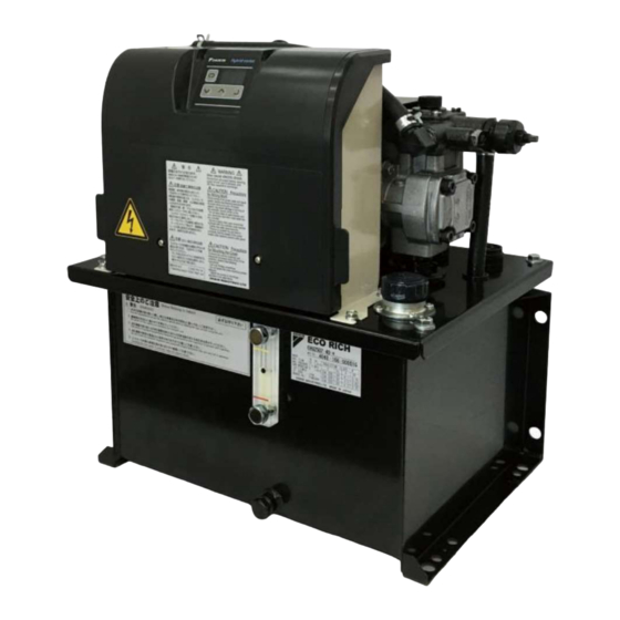
- Page 1 H y b r i d H y d r a u l i c S y s t e m Design #40 Series EHU1404 | EHU2504 EHU2507 | EHU3007...
-
Page 2: Table Of Contents
Table of Contents CHAPTER 1 0BSAFETY INSTRUCTIONS ................ EN-3 12BFor Safe Operation ..................EN-3 13BGeneral Precautions ................. EN-4 14BDisclaimers ....................EN-4 15BRestrictions on Users................EN-5 16BRestrictions on Applications ..............EN-5 17BPrecaution....................EN-5 1.6.1 56BInstallation and wiring ....................EN-6 1.6.2 57BOperation ........................EN-8 1.6.3 58BMaintenance inspections .................. - Page 3 CHAPTER 7 6BCOMPONENT PARTS AND PART NAMES ..........EN-34 CHAPTER 8 7BPROCEDURE FOR STARTING UP ............EN-35 CHAPTER 9 8BTRIAL RUNNING ................. EN-36 CHAPTER 10 9BPANEL OPERATIONS ................ EN-37 10.1 35BNames and Main Functions of Each Part of the Operation Panel ..EN-37 10.2 36BFunctions of the Operation Panel ............
-
Page 4: Chapter 1 0Bsafety Instructions
CHAPTER 1 SAFETY INSTRUCTIONS For Safe Operation Improper handling without regard to this indication will cause an imminently DANGER hazardous condition that may result in death or serious injury. Improper handling without regard to this indication will cause a potentially WARNING hazardous condition that may result in death or serious injury. -
Page 5: 13Bgeneral Precautions
DAIKIN shall not be responsible for any damage attributable to malfunction, etc., resulting from the combination with connected equipment. Daikin shall not be responsible for any injury or accident incurred as a result of equipment operation or maintenance work performed by persons who do not meet the... -
Page 6: 16Brestrictions On Applications
Restrictions on Users DANGER Please restrict the personnel responsible for operating or maintaining equipment to those who have received the necessary training on the handling of the product in advance, fully understand how to the customer. Electrical maintenance in particular must be restricted to those who have certain qualifications prescribed by law (e.g. - Page 7 This hydraulic unit incorporates a safety valve, and its factory default pressure is set to the maximum operating pressure of the hydraulic unit + 0.5 MPa. Adjust the set pressure of the safety valve according to the application. The same applies when the surge pressure upon operation of actuators has to be kept to a minimum.
- Page 8 DANGER Ground the grounding terminals in accordance with the law in the country concerned. Otherwise, there is a risk of electric shock and fire. Make a direct connection without going through a circuit breaker. Make sure that no conductive foreign objects such as screws or metal scraps, or combustible foreign matter such as wood debris or oil, get inside the controller.
- Page 9 1.6.2 DANGER While the product is powered up, do not change the wiring, or connect/disconnect terminals, etc. Otherwise, there is a risk of electric shock, accidents and damage. Do not turn on and shut off the power frequently. Otherwise, there is a risk of failures. CAUTION Set the pressure and flow rate such that they do not exceed the permissible range for the machine.
- Page 10 1.6.5 WARNING The warning plates are very important, so do not damage or remove them. If a warning plate becomes difficult to read through peeling or losses, contact Daikin immediately. This is a warning plate that indicates This is a caution plate for high a high voltage hazard.
-
Page 11: Chapter 2 1Bchecks Upon Receiving The Product
CHAPTER 2 CHECKS UPON RECEIVING THE PRODUCT Check on the Contents of the Packaging CAUTION Check that the product is the right way up, then unpack it. Otherwise, there is a danger of falling and breakage. When the product has been unpacked, check that the following items are present. Hydraulic unit body 1 piece Instruction Manual... -
Page 12: Chapter 3 2Btransportation/Installation
CHAPTER 3 TRANSPORTATION/INSTALLATION Transportation 3.1.1 To transport the product in the packaged state, lift by using the handgrip openings in the cardboard, and transport it on a dolly, for example. The weight in the packaged state is indicated on the label affixed to the side face. WARNING Ensure that transportation work is carried out by people with the required expertise. - Page 13 NOTICE Do not move the product while there is oil in the tank (this could cause malfunctions due to oil leakage or inclusion of air). Installation 3.2.1 Install the unit at a well ventilated location where heat will not build up, and secure a surrounding space of 10 cm from each of the four end faces of the unit.
-
Page 14: 22Bsecuring The Hydraulic Unit
NOTICE If the intake air/exhaust spaces described above are not secured, the motor and controller will reach high temperatures and the lives of the devices will be significantly shortened. Be sure to secure the space for air intake /exhaust. If the intake air/exhaust spaces described above are not secured, the motor and controller will reach high temperatures, temperature protection will be actuated and the product will stop running. - Page 15 CHAPTER 4 HYDRAULIC PIPING Piping Be sure to connect piping at the following ports. Details on the piping positions can be found in the outside view drawing. Use hoses for the piping work, and fasten them with sealing tape. <Piping Specifications> Recommended Hose Piping Port Piping Size...
-
Page 16: 24Bfilling With Hydraulic Oil
CAUTION Use hoses for the piping to this product. Connect the hoses without any twisting. In cases where excessive strain is likely to occur due to the weight of the hose, support the hose. Filling with Hydraulic Oil Remove the cap of the filler port cum air breather by turning it counterclockwise, then pour clean hydraulic oil (within NAS class 10) into the tank. -
Page 17: Chapter 5 4Belectric Wiring
CHAPTER 5 Electric wiring In order to run this product, the main power supply has to be connected. Also connect input/output signal cables as necessary. Connect the main power supply and input/output signal cables after removing the exterior cover. To remove this cover, unscrew the four M4 cross recessed screws. - Page 18 DANGER The wiring work must be done by a qualified electrical engineer. Otherwise, there is a risk of electric shock or fire. Personnel doing wiring work must wear gloves and long sleeves and implement safety measures to avoid injuries such as grazes. Personnel doing wiring work must wear gloves and long sleeves and implement safety measures to prevent electric shocks and fire due to static electricity.
-
Page 19: 25Bprocedure For Mounting Exterior Covers
Procedure for Mounting Exterior Covers After connecting the main power supply and input/output signal cables, the exterior cover needs to be mounted. Mount it by following the procedure below. Controller box Exterior cover Engage the corners of the controller and corners of the cover together. Close the cover. - Page 20 Press in the vicinity of the two screws at the bottom of the exterior cover to position it. When pressing the vicinity of the screws, confirm that a clicking sound is heard as the projections on the exterior cover go into the mating parts on the interior cover. Vicinity of screws Interior cover Exterior cover...
-
Page 21: 26Boverall Wiring Diagram
Overall Wiring Diagram Input power supply 3 200/200/220 V 50/60/60 Hz Digital output Power supply Control power supply input Ready to run line ground 1 200/200/220 V 50/60/60 Hz Positive common Negative common External power supply (DC+24 V) Max. current 50 mA option is selected Digital input Start/stop signal... -
Page 22: 27Binstallation Of The Breaker
Installation of the Breaker In order to prevent power-supply-related accidents, be sure to use a no-fuse breaker conforming to EN60947-2 in the power supply connection line. The rated capacity of the breaker should be as indicated in the table below. There are no inrush currents with EcoRich. - Page 23 Connect the power cable to the terminal block. The recommended tightening torque is 1.0 N m. Power supply cable port 23 hole Grounding connection Shutter opens. Power supply connection terminal Lever From left: L1, L2, L3 Terminal block securing screws Press in the direction Do not use these for power shown by the arrow...
-
Page 24: 29Bconnection Of Input/Output Signal Cables
Connection of Input/Output Signal Cables Prepare a cable and cable clamp. <Recommended Items> Cable Size Recommended Cable Recommended Cable Clamp OA-W15M-07 (OHM ELECTRIC) KVC-36SB 0.3 0.5 mm 0.3 - 0.5 mm (AWG20 - 22) Applicable cable outer diameter: (Kuramo Electric) If not using input/output signals, fit a blanking cap and ensure the protection class is satisfied. - Page 25 Terminal Terminal Signal Name Remarks Signal Name Remarks Code Code COM1 Digital output common ALMa Alarm output, NO contact 5.5.2 Digital 5.5.3 Contact output DOUT Digital output ALMb Alarm output, NC contact output DIN0 Digital input 0 Alarm output common DIN1 Digital output 1 5.5.1 Digital...
- Page 26 5.5.1 These are sequence input signals that control the operations of this unit from an external device. Connect them as necessary by following the information below. Terminal Name Signal Name Remarks COM2 Digital input common Can be either positive or negative Start/stop signal (At shipment from factory: Start when OFF/stop DIN0 Digital input 0...
- Page 27 5.5.2 due to pressure holding speed drop) alarm and L67 (pressure holding speed drop) warning status. Connect them in accordance with the instructions below as necessary. Terminal Name Signal Name Output Content: factory default setting DOUT Digital output Disabled (goes OFF (closed) when ready to run) COM1 Digital output common Can be either positive or negative...
- Page 28 5.5.3 These are the contact output signals that output the alarm statuses of this unit. Connect them as necessary by following the information below. Terminal Signal Name Output Content: factory default setting Name The NO contact becomes closed when power supply turns ON. ALMa Alarm output, NO contact When an alarm (E ) or L70 (reverse rotation warning) occurs or a pressure...
-
Page 29: Chapter 6 5Bproduct Specifications And Conditions Of Use
CONDITIONS OF USE CAUTION Be sure to use the product within the specifications and observe the conditions of use. Daikin shall not be responsible for any accident or loss attributable to failing to follow this instruction. Product Specifications Product Model... - Page 30 Nomenclature Model No. Maximum flow rate EHU: ECORICH Series 14: 15.2 L/min 25: 25.1 L/min 30: 28.5 L/min Maximum operating pressure Design No. Design 40 series 04: 4 MPa (Incremented at model changes) 07: 7 MPa Controller option (s) (in alphabetical order when combined) C: With RS422/485 communications function S: With separated power supplies for power and control lines N: No controller option and with unit options...
-
Page 31: 31Bconditions Of Use
Conditions of Use Mineral- Viscosity grade: ISO VG 32 to 68 - Contamination: Within NAS class 10, water content 0.1%vol max. Useable oil (Note 1) Dynamic viscosity range: 20 to 88 mm /s (recommended values), 15 to 400 mm (usable range) Tank oil temperature range: 15 to 50 C (recommended values), 0 to 60 C (usable range) (Note 3) -
Page 32: 32Bpq Representative Characteristic Diagram
PQ Representative Characteristic Diagram P pressure (MPa) P pressure (MPa) P pressure (MPa) P pressure (MPa) -
Page 33: 33Bexternal Dimensions
External Dimensions... -
Page 34: 34Bhydraulic Circuit
Hydraulic Circuit Part No. Name Oil tank Suction strainer Oil level gauge Above the oil level Inverter driven motor pump Control unit Oil filler port cum air breather Oil cooler... -
Page 35: Chapter 7 6Bcomponent Parts And Part Names
CHAPTER 7 COMPONENT PARTS AND PART NAMES Control unit Safety valve Operation panel Oil cooler DC fan Inverter driven motor pump Oil filler port cum air breather Oil level gauge Oil tank Oil filling / drain port... -
Page 36: Chapter 8 7Bprocedure For Starting Up
CHAPTER 8 PROCEDURE FOR STARTING UP The procedure for starting up the product is as follows. Be sure to check the following points before turning the power on. Is the product installed correctly? Has the piping been done correctly? Has hydraulic oil been supplied? Has the wiring been done correctly? Is the power supply voltage correct? Check the operation of the actuators. - Page 37 CHAPTER 9 TRIAL RUNNING CAUTION Ensure that the power can be shut off immediately in response to unforeseen events. Either incorporate an emergency stop switch or similar device, or configure a sequence circuit for the main machine for that purpose. Before running the unit, stop it temporarily and check for safety even in the event of unanticipated operation.
-
Page 38: Chapter 10 9Bpanel Operations
CHAPTER 10 PANEL OPERATIONS 10.1 Names and Main Functions of Each Part of the Operation Panel MODE key Data display (3 digits) The controller features the 3-digit data display and four key-switches indicated in the figure to the left. The LED display normally shows the current actual pressure (MPa). -
Page 39: 36Bfunctions Of The Operation Panel
10.2 Functions of the Operation Panel 10.2.1 The operation panel has the following functions. Mode Details Regular mode Displays the current pressure. The unit at shipment is MPa. Monitor mode Enables checking of the pressure, command voltage and current value of the flow rate, etc. Setting mode Enables setting of the various parameters. - Page 40 10.3 Regular Mode In the regular mode, the display is as follows depending on the status at the time. Status Panel Indication Details Powering on At powering on, all the LEDs flash momentarily. Normal In the normal status, the current pressure is displayed. Displayed when a stop command is in effect, and when the pressure is Stopped 0.15 MPa or lower.
- Page 41 Monitor No. Name Unit Details Total operation time (minutes) Total operation time Displays the total operation time after shipment from the factory (hours) (time the motor is energized). Total operation time (thousands of hours) 1,000 h (thousands of hours) Power consumption Displays the current approximate power consumption.
- Page 42 10.4.2 Monitor mode Selection of data number Value display Regular mode One of The data number selected after the maximum data number returns to n00. Press the key in the regular mode. The mode will switch to the monitor mode. Select the data number to be displayed by using the key or key.
- Page 43 10.5 Setting Mode 10.5.1 Regular mode Holding down together (approx. 2 seconds) Setting mode Selection of data number Value display Value editing Confirmation The data number selected after the maximum data number returns to P00. Hold down the keys together in the regular mode. After about 2 seconds, the mode will switch to the setting mode.
- Page 44 PQ selection parameters Regular mode Holding down together (approx. 2 seconds) Setting mode Data selection and value display/editing Selection of data number Elapse of 2 seconds Elapse of 2 seconds Elapse of 2 seconds Elapse of 2 seconds Elapse of 2 seconds Elapse of 2 seconds Hold down the keys together in the regular mode.
-
Page 45: 40Balarm Mode Display
10.6 Alarm Mode Display The alarm mode enables checking of up to 10 alarms in the history of alarms that have occurred in the past. 10.6.1 Regular mode Holding down together (approx. 2 seconds) Alarm mode History of alarm numbers Alarm data display Latest alarm Elapse of 2 seconds... - Page 46 Press the key. This returns you to the alarm history number. Panel Display Item Remarks Indication Unit Alarm details Alarm details Number of Power-on count Power-on count at occurrence of the alarm times Motor speed at alarm 10 min Rotational speed of the motor at occurrence of the alarm occurrence Effective motor current Effective current value of the motor at occurrence of the...
-
Page 47: Chapter 11 10Bmaintenance
When an alarm has occurred at the unit, the alarm number is displayed on the operation panel. Take prompt action by referring to the table below. WARNING If you have any concern about how to deal with an alarm, be sure to contact Daikin. Operation panel... - Page 48 11.2 Alarm Causes and Corrective Actions Alarm Name Cause Corrective Action Code Adjust the setting of the safety valve to the operating pressure + 0.5 MPa. Motor control error If there is a possibility of large hydraulic load due to deterioration of the oil, change the oil. Adjust the lowest rotational speed.
- Page 49 Alarm Name Cause Corrective Action Code Set value for the safety valve is too Adjust the setting of the safety valve to the high. operating pressure + 0.5 MPa. Motor control error Controller failure Replace controller. Excessive load torque at starting due Replace hydraulic oil.
- Page 50 Alarm Name Cause Corrective Action Code Replace the cooling fan. The cooling fan has stopped. Replace controller. The radiator is clogged. Clean or replace the radiator. Check if the amount of oil leaking from the circuit at the main machine has increased. Abnormal temperature The motor rotation speed has risen.
-
Page 51: 43Bwarning Causes And Corrective Actions
11.3 Warning Causes and Corrective Actions Warning Name Cause Corrective Action Code Replace the cooling fan. The cooling fan has stopped. Replace controller. Replace the fan harness. The radiator is clogged. Clean or replace the radiator. Motor abnormal Check if the amount of oil leaking from the circuit at temperature warning the main machine has increased. -
Page 52: 44Bperiodic Maintenance
Warning Name Cause Corrective Action Code The pressure reached the If there is nothing abnormal in the operation of the Pressure switch main machine, review the set value for the pressure actuation switch or the delay time. Clean the throttle of the safety valve. The flow channel (throttle Holding pressure Adjust the minimum rotational speed adjustment... -
Page 53: 45Bcleaning/Replacement Work
Inspection Inspection Inspection Instructions Location/Item Timing/Interval Control unit Once a month Check if the ambient temperature has exceeded 40 C. Check that there are no cracks or breaks in the sheathing of the wiring. Once every 6 Electric wiring months Check that the ground is properly grounded. -
Page 54: 46Boil Cooler Maintenance Instructions
DANGER When touching the interior of the controller, abide by the following procedure to prevent electric shocks. Shut off the source power supply to the hydraulic unit. (Set the power supply circuit breaker of the circuit that is supplying the power to power supply circuit breaker or other device, preventing erroneous operation while the work is in progress. - Page 55 11.6.1 Disconnect the connector for the DC fan wiring. Remove the hose clamps (2 locations), and pull off the two hoses fitted to the oil cooler. At this time, fit e.g. a blind plug to the hoses before starting further work since oil may leak due to reverse flow of oil from the tank.
- Page 56 11.6.3 Steam blow or air blow the core to blow dirt and contamination that has been deposited on or is adhering to the fins, making the fin section clean. WARNING When using air blow, wear protective glasses to avoid getting deposits and dirt in your eyes.
-
Page 57: 47Boil Filler Port Cum Air Breather Maintenance Instructions
11.7 Oil Filler Port cum Air Breather Maintenance Instructions WARNING Before starting maintenance work, stop the unit running and shut off the source power supply. Wear protective glasses and gloves for this work. 11.7.1 To remove it, turn the cap in the counterclockwise direction by hand. To fit it, turn the cap in the clockwise direction by hand to the position where it stops. -
Page 58: 49Bsafety Valve Adjustment Instructions
11.8.2 Air blow the suction strainer to blow off deposits and adhering material. Also remove foreign matter inside the cylinder part of the strainer. WARNING When using air blow, wear protective glasses to avoid getting deposits and dirt in your eyes. 11.8.3 After completing the cleaning, reassemble by following the removal procedure in reverse. - Page 59 When the pressure setting has been changed after shipment from Daikin peripheral devices such as pressure gauges, it is advisable to set [Safety Valve Adjustment Instructions] Referring to the enlarged view of the safety valve on the next page, loosen the lock nut.
-
Page 60: 50Bfixed Throttle ( 0.8) Mounting Instructions
11.10 Fixed Throttle ( 0.8) Mounting Instructions When using the unit with a set pressure of 6 MPa or higher, if the pressure becomes unstable due to the effects of contaminants, etc., mount the fixed throttle ( 0.8) provided as an accessory. Check that there is no residual pressure before mounting it. - Page 61 11.11 Minimum Rotational Speed Adjustment Instructions In case the pressure setting is changed or the fixed throttle is installed, rotational speed in the pressure holding status would be changed. Adjust to the appropriate speed(380min machine it will not be possible to adjust to the appropriate rotational speed due to the influence of leakage from the valves, actuators, etc.
-
Page 62: 52Btiming Chart At Powering Up
CHAPTER 12 APPENDIX The start/stop signals (digital input 0) in the timing charts all assume that the value set for [P00: Start/stop signal (digital input 0) are inverted. 12.1 Timing Chart at Powering Up The timing chart at powering up differs depending on the type of power supply as shown below. When sharing control power supply Judge the charging completed/not completed status based on the alarm output or DOUT (READY output). - Page 63 Panel Default Code Name Operation Range Details Indication Value Pressure Sets the delay time from when the pressure T_SW switch output 0.00 to 9.99 [sec] 0.00 delay time When the displayed on the operation panel can be retained. It is also possible to record the Pressure switch the alarm history, although it is not usually...
- Page 64 Panel Default Code Name Operation Range Details Indication Value Dry operation 0.00 to 2.00 [MPa] 0.50 DR_L judgment 0 to 290 [PSI] pressure Dry operation DR_T 0.01 to 9.99 [sec] 3.00 judgment time Sets the threshold for detecting pressure 0.00 to 1.00 [MPa] 0.50 Pressure recovery from actuation of the pressure...
- Page 65 Panel Default Code Name Operation Range Details Indication Value Pressure attainment Sets the differential pressure between the signal pressure at which the pressure attainment PFD2 0.00 to 1.00 [MPa] 0.00 canceling signal comes ON and the pressure at which it differential goes OFF.
-
Page 66: 54Babout The European Directive On 400 V Specifications
12.3 About the European Directive on 400 V Specifications The European Directives are directives aimed at the smooth distribution of products whose safety has been guaranteed within EU member states. Sales managers within the EU area Company: BIBUS ITALIA Srl Address: Via Tosarelli, 336/4 40055 Villanova di Castenaso (Bo) Italy... -
Page 67: 55Babout Hybrid-Win (Maintenance/Control Functions
ABOUT Hybrid-Win (MAINTENANCE/CONTROL FUNCTIONS) Hybrid-Win is a software tool for reading and controlling the information of a Daikin hybrid system (SuperUnit, EcoRich, Oilcon, etc.) on a personal computer. It makes it possible to set and monitor parameters efficiently from a Windows screen on the personal computer. - Page 68 Fax.: 81-6-6349-7862 http://www.daikinpmc.com/en/ Home Page: Contact: http://www.daikin.com/contact/hydraulic/ For requirements on Maintenance Repair Operation; All World Machinery Supply, Inc. a member of Daikin Group 6164 All World Way, Roscoe, IL 61073, U. S. A. Phone: +1-815-943-9111 Fax.: +1-815-943-5370 http://www.allworldmachinery.com/us/ Home Page:...
Need help?
Do you have a question about the ECORCH 40 Series and is the answer not in the manual?
Questions and answers