
Related Manuals for biochrom Ultrospec 50


Summary of Contents for biochrom Ultrospec 50
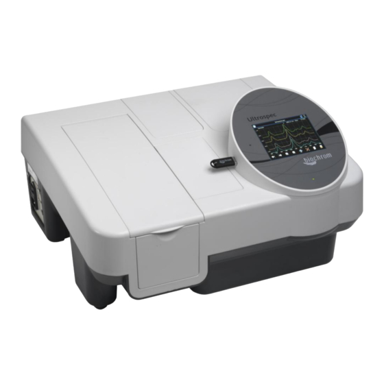
- Page 1 Biochrom Ultrospec 50, 60, 70 & 80 UV Visible Spectrophotometers Accessories User Manual...
-
Page 2: Table Of Contents
TABLE OF CONTENTS: HEALTH & SAFETY ........................... 1 OPERATION ............................. 1 INSTALLATION ..........................1 PASSIVE ACCESSORIES ........................2 4.1. SINGLE CELL HOLDER ......................3 4.2. VARIABLE PATHLENGTH CELL HOLDER ................... 4 4.3. WATER THERMOSTATED CELL HOLDER .................. 4 4.4. FILM HOLDER .......................... 4 4.5. -
Page 3: Health & Safety
Note: The images in this manual show the installation of accessories in a double beam instrument. Accessories are installed in split beam instruments in exactly the same way. All accessories detailed in this manual are available for both split beam (Ultrospec 50) and double beam instruments (Ultrospec 60, 70 & 80). -
Page 4: Passive Accessories
4. PASSIVE ACCESSORIES Accessories that do not interact with the instrument’s software are named passive accessories. There installation is described below: To allow easy access to the thumbscrew at the front of the accessory open the cell chamber lid and lift out the front panel (below left). -
Page 5: Single Cell Holder
With the accessory inserted simply replace front panel, switch on the instrument and it will be ready to use. 4.1. SINGLE CELL HOLDER The single cell holder is designed to take measurements of 10 mm pathlength cuvettes. All Biochrom Ultrospec are supplied with a single cell holder as standard. Issue 02... -
Page 6: Variable Pathlength Cell Holder
4.2. VARIABLE PATHLENGTH CELL HOLDER The variable pathlength cell holder is designed to use 1, 2, 5, 10, 20, 50 & 100 mm pathlength cells. To accommodate different pathlengths the clips should be moved to secure the cell and spacers used as required. 4.3. -
Page 7: Test Tube Holder
4.5. TEST TUBE HOLDER The test tube holder allows samples to be measured in a test tube of between 10 and 24mm diameter and up to 160mm tall Issue 02... -
Page 8: Peltier Controlled Fluid Circulator
4.6. PELTIER CONTROLLED FLUID CIRCULATOR Content 4.6.1. GENERAL INFORMATION ....................7 4.6.1.1. General Warnings ....................7 4.6.1.2. Quality, Reliability and Safety ................. 7 4.6.1.3. SAFETY MARKINGS ....................8 4.6.2. INSTRUMENT DESCRIPTION .................... 8 4.6.2.1. Controller front and rear panel ................9 4.6.2.2. -
Page 9: General Information
The equipment must be used in accordance with the instructions for use provided by BIOCHROM. All modifications and repairs to the equipment must be carried out by BIOCHROM or its authorised Agents. Modifications must not be carried out unless they conform to approved Engineering Service Information issued according to the appropriate BIOCHROM procedure. -
Page 10: Safety Markings
The publication may not be reproduced in part or in whole without written consent of BIOCHROM. In order to maintain and improve standards of manufacturing, methods of functioning and to increase reliability, BIOCHROM equipment is periodically reviewed. -
Page 11: Controller Front And Rear Panel
4.6.2.1. Controller front and rear panel The front and the rear panel have grids to dissipate the heat generated in the unit. Two fans force the air movement. These grids must be free to guarantee the instrument specifications. The front panel features the display with keypad. The rear panel features the mains power connection with mains voltage selector, the USB connector for remote control, the mains switch and the "Water Fill"... - Page 12 4.6.2.2.5. External Control Possibilities USB as standard. 4.6.2.2.6. Dimensions Width: 170 mm Height: 280 mm Depth: 430 mm Weight: 6 kg 4.6.2.2.7. Electrical data Mains supply: 115/120 V or 220/240 V t 10% (factory setting 220/240 V) Frequency: 50/60 Hz ...
-
Page 13: User Interface
4.6.2.2.8. Description of Symbols Caution (Refer to accompanying documents). Symbol identifying the use of substances dangerous for health and environment. For these substances reference must be made to the laws and standards in force in the laboratory where this instrument is used. If using flammable or explosive substances take the necessary precautions. -
Page 14: Installation
The plate containing the serial number is located on the rear panel at the base of the unit. Check that this number is identical to the serial number on the delivery note. If not, please inform BIOCHROM immediately. 4.6.3.2. Checking mains supply and fuses The Controller is factory set to operate at 220 VAC. -
Page 15: Instrument Set-Up
4.6.3.2.1. Changing the Mains Voltage Setting and Fuses The voltage set is shown in the window of the voltage selector below the mains input connection. To change this setting switch off the unit at the mains switch, remove the mains cable and proceed as follows: Slide out the fuse holder by inserting a small screwdriver alternatively into the two slots at the left and right and pulling it out of the housing. -
Page 16: Operating Instructions
The Controller has no special electrical external connections which would allow relay control etc. Operations are performed either manually or via remote control using the USB connections. Contact BIOCHROM for further information about the remote control functions. 4.6.4. OPERATING INSTRUCTIONS 4.6.4.1. - Page 17 Menu page and functions of the buttons Menu Description L button Middle R button button Parameter User parameters Scroll Select Exit Configuration Configure Scroll Select Exit parameters Diagnostic Diagnostic values Scroll Select Exit Parameters setting User parameters and functions of the buttons Number Description Default L button...
-
Page 18: Maintenance
4.6.5. MAINTENANCE The Controller requires very little routine maintenance by the user. Any operation that requires the units to be opened must only be performed by BIOCHROM technicians or authorized personnel. Always unplug from the mains when opening the units 4.6.5.1. -
Page 19: Troubleshooting
4.6.6. TROUBLESHOOTING The Controller is able to indicate malfunctions and incorrect use. The messages available are directly visible on the display, indicated audibly or transmitted via USB for remote communication. 4.6.6.1. Audible alarm The Controller will send an audible alarm if either a leakage was detected or another failure occurs. 4.6.6.1.1. -
Page 20: Active Accessories
The installation of active accessories that use the internal accessory connector is outlined below. Note: The Biochrom Ultrospec will be supplied with a single cell holder as standard; this is removed as described above. -
Page 21: 8-Position Cell Changer
5.1. 8-POSITION CELL CHANGER The 8-position cell changer is designed to speed up analysis by allowing users to automatically measure samples. With a cell changer connected the software will allow the user to perform parallel kinetics measurements. 5.2. 5-POSITION THERMOSTATTED CELL CHANGER The 5-position thermostatted cell changer is designed to speed up analysis by allowing users to automatically measure samples that are at a... -
Page 22: Sipper & Flowcell
5.3. SIPPER & FLOWCELL The sipper is designed to speed up analysis by allowing users to automatically measure samples by pumping them through a flowcell using a peristaltic pump head. To install the sipper carry out the following steps Pump head Start/Stop button Sample beak –... - Page 23 80-2055-13 PTFE tubing with flowcell connectors The tubing supplied with the flowcell from Biochrom is 150cm in length to allow customers flexibility in how they sip from their sample vessels. Unless you require tubing this long for your application take the tubing with the short flowcell connector attached and cut the tubing to 65cm in length.
- Page 24 Take the tall flowcell connector and connect it to the outlet port of the flowcell. Slide the whole sipper unit up and feed the end of the tube through the hole in the front panel underneath the pump head, once again from the inside out and then slide the sipper unit back down in it’s slot.
- Page 25 5.3.1.1. Sipper Troubleshooting Problems with sipper systems are generally caused by wrongly set parameters or poor maintenance. Typical faults and their cures include: 5.3.1.1.1. Sample not being sipped Check pump head closed Check pump head tubing for damage ...
-
Page 26: Installing The Internal Printer
6. INSTALLING THE INTERNAL PRINTER Ensure that the instrument is unplugged before installing the internal printer. 1. Before the internal printer can be installed the printer blanking panel must be removed. This is accessed from the back of the unit. 2. - Page 27 5. Slide the front legs of the printer in place and lower into the correct position. 6. Secure to the instrument by screwing into place. Reconnect the instrument to the mains and switch on. Once installed the internal printer will appear in the list of available printer options.
Need help?
Do you have a question about the Ultrospec 50 and is the answer not in the manual?
Questions and answers