
Related Manuals for biochrom HB Ultrospec 7500


Summary of Contents for biochrom HB Ultrospec 7500
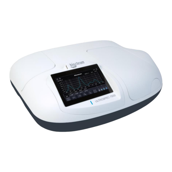
- Page 1 Ultrospec 7500 Spectrophotometer USER MANUAL ORIGINAL INSTRUCTIONS • 41 56 2050 REV03 •...
- Page 2 Intentionally blank Ultrospec 7500 User Manual • 41 56 2050 REV03 •...
-
Page 3: Table Of Contents
TABLE OF CONTENTS ESSENTIAL SAFETY NOTES Hazards and Warnings INTRODUCTION The Biochrom Ultrospec Spectrophotometers INSTALLATION Unpacking Positioning Installing WARRANTY AND REPAIR Warranty Policy Returns INSTRUMENT OVERVIEW Scope Spectrophotometer Principle and Intended Use Hardware Technical Specifications Touchscreen Display Instrument Connections PVC PC Software... - Page 4 GLP Settings GLP application GLP error Switch User Instrument Status Instrument Information Instrument Settings Lamp Settings Instrument Reset Applications Single Wavelength Wavescan Kinetics Standard Curve Substrate Equation Editor Protein Protein UV Colorimetric Protein Protein Dye Oligo Fluorescent Dye OD 600 Tm Calculation Methods Favourites...
- Page 5 TROUBLESHOOTING PRINTING Printing Sample Data External Printer Print Via Computer (PVC) Manual Printing Installing the External Printer ACCESSORIES Accessory Part Numbers Accessory Installation Guide CONTACT INFORMATION Ultrospec 7500 User Manual • 41 56 2050 REV03 •...
- Page 6 Intentionally blank Ultrospec 7500 User Manual • 41 56 2050 REV03 •...
-
Page 7: Essential Safety Notes
ESSENTIAL SAFETY NOTES Hazards and Warnings This section describes potential hazards which may exist in the operation of these units. Several warning labels and symbols are affixed to your instrument. These symbols are used to inform you of potential dangers which may exist or where caution is required. Before installing your new unit, please take time to familiarise yourself with these warnings and symbols. -
Page 8: Introduction
INTRODUCTION The Biochrom Ultrospec Spectrophotometers Spectrophotometers are ubiquitous among modern laboratories. Ultraviolet (UV) and Visible (VIS) spectrophotometry has become the method of choice in most laboratories concerned with the identification and quantification of organic and inorganic compounds across a wide range of products and processes. Applied across research, quality, and manufacturing, with continuing focus on life science and pharmaceutical environments, they are equally as relevant in agriculture, animal husbandry and fishery, geological exploration, food safety, environmental monitoring, and many manufacturing industries to name a few. -
Page 9: Installation
INSTALLATION Unpacking • The unit weighs ~13 kg. No special handling is required. • Please keep the original packaging for transport for service or repair as it has been specifically designed to protect the unit from damage during transit. • Inspect the instrument and its power supply for any signs of damage caused during transit. If any damage is discovered, do not use the instrument, and report the problem to your supplier. -
Page 10: Warranty And Repair
Warranty Policy Biochrom warrants these instruments for a period of 24 months (2 years), and an additional 12 months (3 years in total) for the xenon lamp, from the date of purchase. Where appropriate, Biochrom will repair or replace the unit for defects of workmanship or materials. This warranty does not extend to damage resulting from misuse, neglect, or abuse, normal wear and tear, or accidental damage. -
Page 11: Instrument Overview
INSTRUMENT OVERVIEW Scope This user manual covers the following range of Biochrom UV/Visible spectrophotometers: Part Number Description 80-2140-60 Ultrospec 7500 Spectrophotometer Principle and Intended Use UV/Visible spectrophotometers measure the transmission of light through a sample. Samples absorb light based on their unique molecular composition. -
Page 12: Technical Specifications
Technical Specifications Wavelength range 190 to 1100 nm Monochromator 1200 lines/mm Aberration corrected concave grating Wavelength calibration Automatic upon switch on Beam Height 15 mm Spectral bandwidth <2 nm Wavelength accuracy ±1 nm Wavelength reproducibility ±0.5 nm Light sources Xenon flash lamp Detector two silicon photodiodes Photometric range... -
Page 13: Pvc Pc Software
Biochrom Resolution PC Software When connected to a PC the spectrophotometer can be controlled using the Biochrom Resolution PC software packages (sold separately). Operation using Biochrom Resolution PC software is described in the Resolution user manual or Resolution help file. -
Page 14: User Interface
USER INTERFACE Colour Touchscreen The instrument is controlled using the colour display and touchscreen. The onscreen keyboards and number pad, and frequently used icons are detailed in this section of this operating manual. Onscreen Keyboards and Number Pad “QWERTY” Alphanumeric Keyboard Text Panel Alphanumeric keys Backspace... -
Page 15: Frequently Used Icons
Special Character Keyboard Text Panel Special Character Keys Backspace Caps Lock “QWERTY” Confirm Keyboard Symbol Spacebar Keyboard Number Pad Number Panel Numeric Keys Clear Decimal Point Cancel Confirm + or - Toggle Key Frequently Used Icons The frequently used icons detailed in this section are to support the quick-start operation of the instrument. Method specific icons are detailed in the relevant method section. -
Page 16: Common Icons On The Options Menu
Common Icons on the Options Menu Exit Exit the application and return to the application menu Save data Save the sample data Save method Save the method with the current parameter’s settings Print Print the sample data from the specified printer Auto-print Toggle auto print on (green) or off (red) Go to std Curve... -
Page 17: Instrument Firmware
Instrument Firmware The instrument firmware uses an intuitive menu arrangement that is navigated using the colour display icons and touchscreen. First-time Start-Up Upon first powering up of the instrument, the following screen sequence is displayed. 1: Self-calibration routine screen 2: Regional settings page. Select the appropriate settings according to your location 3: Date and time setup page. -
Page 18: Login Screen
Home screen for the Ultrospec 7500 spectrophotometer when Home screen for the Ultrospec 7500 spectrophotometer User Login is available displaying the USB memory stick application and screenshot camera icon, made available when a USB flash drive is inserted and User Login available Login Screen The instrument Ultrospec 7500 login screen is the first screen displayed after self-initialisation of the instrument if the ‘Show Login’... -
Page 19: Power Off
Power Off To Power off the instrument switch off the main switch to the off (0) position. Main switch and 19 VDC power supply socket Settings The Settings screen is accessed from the home screen settings icon . The settings screen can be used to adjust the instrument settings: date and time, regional, data output, user interface, accessories, user access, service and GLP settings. -
Page 20: Regional
Regional The Regional application is accessed from the Settings screen. It can be used to change the language and decimal separator number format. There are several setting options available. Select the language from the selection menu. Toggle between full stop and comma number format decimal separator. -
Page 21: Accessories
Accessories The Accessories application is accessed from the Settings screen. It can be used to identify which accessories are fitted to the instrument and to define their default settings. The example below shows the 10 mm pathlength, 8 position cell changer that comes as standard with the Ultrospec 7500. - Page 22 Editing the “Administrator” user account allows to enable the login function upon start-up of the unit for all the users. Select “Yes” in the Show Login box to enable the user login upon start up. The default Administrator password is 1000. New accounts can be assigned to 3 permission groups.
-
Page 23: Glp Settings
GLP Settings The GLP Settings application is accessed from the Settings screen. It can be used to define the GLP routine preferences. There are several GLP setting options available. Set the GLP frequency from the selection menu, from “Always”, “Daily”, “Weekly”, “Monthly”, or “Quarterly”. Set auto print to “On”... -
Page 24: Switch User
Switch User The switch user icon is visible on the home screen toolbar, providing the ‘Show Login’ setting is enabled on the ‘Edit User Access – Parameters’ screen for the default Administrator user. It is used to change the active user on the instrument without having to restart the instrument first. -
Page 25: Instrument Settings
Instrument Settings The Instrument Settings screen is accessed from the Instrument Status screen. It can be used to create and store a new instrument baseline. From the Instrument Status screen, select the instrument settings icon. There are several setting options available. Create a new temporary baseline, using the new baseline icon. -
Page 26: Instrument Reset
Instrument Reset The Instrument Reset screen is accessed from the Instrument Status screen. It can be used to delete all the user data from the instrument. From the Instrument Status screen, select the instrument reset icon. There are several setting options available. Delete all user samples, using the delete samples icon. -
Page 27: Applications
Applications The Applications screen is accessed from the home screen. It contains basic applications with definable parameters to meet the needs of typical laboratory protocols. Single Wavelength The Single Wavelength application is selected from the Applications screen. It can be used to perform simple absorbance (A) and % transmission (%T) measurements. - Page 28 Step 4 If “Concentration” mode is selected. Proceed to the next parameter screen using the right/forward arrow. Step 5 Select the factor method to be applied to the absorbance value from “Predefined” or “Standard”. Step 6 Set the factor or concentration value to between -9999 and 9999, according to the factor method selection of “predefined”...
- Page 29 Step 14 Press the batch measurement icon, then load the cell changer according to the cell changer prompt. Confirm when ready to take measurements. Step 15 The acquired reference sample baseline will be applied to all subsequent sample measurements. The sample measurements can be viewed by pressing the sample name test box and selecting the appropriate sample from the list.
-
Page 30: Wavescan
Step 19 Replace the previous sample with a test sample then take a sample measurement using the sample measurement icon. Repeat for all samples. Step 20 Return to the Applications screen using the exit icon in the options menu OR use the additional options to save, print, and, or load previous measurements (see the Additional Options section). - Page 31 For “Custom” feature detection, also set the custom peak height and width triggers. For “Multi λ” feature detection, set the number of wavelengths to extract the absorbance at to “1”, “2”, “3”, “4”, “5”, “6”, “7”, or “8”. Then set those wavelengths to between the previously defined minimum and maximum wavelengths, 190 –...
- Page 32 Step 18 Press the batch measurement icon, then load the cell changer according to the cell changer prompt. Then select the confirm icon. If using a cell changer, skip steps 19 through 20 and go straight to step 21. Step 19 Insert the reference sample then take a reference measurement using the reference measurement icon.
- Page 33 Additional viewing tools as available at the bottom of the screen. Cursor left Move the x-axis cursor position left Cursor right Move the x-axis cursor position right Zoom in Zoon into the area around the x and y-axis cursor position Zoom out Zoon out from the area around the x and y-axis cursor position Step 22...
-
Page 34: Kinetics
Kinetics The Kinetics application is selected from the Applications screen. It can be used to perform a series of absorbance (A) measurements over a defined timeframe creating a time-course trace. Step 1 Set the wavelength to between 190 and 1100 nm. Step 2 Select the sample name to bring up the sample window, enter a sample seed prefix and the incremental sample number starting value. - Page 35 Step 9 Proceed to the next parameters screen using the right/forward arrow. Step 10 Set the mode to define the desired result, “Delta A”, “Final A”, or “Slope”. Step 11 Set the factor value to be applied to the result, between 0.000 and ±9999. Step 12 Define the units that the result value will be reported in.
- Page 36 Step 19 Press the batch measurement icon, then load the cell changer according to the cell changer prompt. Then select the confirm icon. If using a cell changer, skip steps 20 through 21 and go straight to step 22. Step 20 Insert the reference sample then take a reference measurement using the reference measurement icon.
- Page 37 Zoom out Zoon out from the area around the x and y-axis cursor position Step 23 Return to the Applications screen using the exit icon in the options menu OR use the additional options to save, print, and, or load previous measurements (see the Additional Options section).
-
Page 38: Standard Curve
Standard Curve The Standard Curve application is selected from the Applications screen. It can be used to create a calibration curve from standard samples of known concentration. The curve fit equation is then applied to the absorbance (A) measurements of any subsequent test samples to determine their concentration. - Page 39 Step 9 Proceed to the next parameter screen using the right/forward arrow. Step 10 Enter the concentration values of the standards samples between - 9999 to 9999. Confirm the settings using the confirm icon. Step 11 Proceed to the next parameter screen using the right/forward arrow. Step 12 Set auto print to “On”...
- Page 40 If using a cell changer, skip steps 18 through 23 and go straight to step Step 18 Proceed to the next parameter screen using the right/forward arrow. Step 19 Take a reference using the reference icon, then insert standards and take each standard measurement by using the measurement icon If not using replicates, ship to step 26 Step 20...
- Page 41 Step 24 Leave the replicates function using the left/backward arrow. Step 25 If the source of the calibration is set to “Standards”, skip step 25 and go to step 26. If source of the calibration is set to “Manual”. Define each standards absorbance value by selecting the appropriate text box and entering a value between -0.3 and 3.0 A.
- Page 42 If using a single cell holder, or a cell changer set to use as a single cell holder, skip steps 29 through 30 and go straight to step 31. Step 29 Press the batch measurement icon, then load the cell changer according to the cell changer prompt.
-
Page 43: Substrate
Substrate The Substrate application is selected from the Applications screen. It can be used to create a calibration curve from kinetic measurements of samples of known concentrations. The curve fit equation is then applied to the absorbance (A) measurements of any subsequent test samples to determine their concentration. - Page 44 Step 15 Select one of the predefined units; “μg/ml”, “ng/μl”, or “μg/μl”. Select “Custom” and define the custom units that the concentration value will be reported in. Step 16 Enter the concentration values of the standards samples between -9999 to 9999. Confirm the settings using the confirm icon. Step 17 Proceed to the next parameter screen using the right/forward arrow.
- Page 45 Step 24 Then select the confirm icon. Step 25 Acknowledge the on-screen prompts by selecting the confirm icon. Repeat for all replicate and standard samples. If using replicates, any of the standards or replicates can be re-run, by highlighting the appropriate standard and selecting the replicates icon. Cycle through the standards using the right/forward arrow, and leave the replicates function by cycling back through the standards using the left/backward arrow.
- Page 46 Step 28 Replace the reference sample with the first standard sample then take a sample measurement using the sample measurement icon for each replicate of that standard sample. Step 29 Proceed to the next standard measurement screen using the right/forward arrow. Step 30 Replace the previous standard sample with the next standard sample then take a sample measurement using the sample measurement icon for each...
- Page 47 If using a single cell holder, or a cell changer set to use as a single cell holder, skip steps 35 through 36 and go straight to step 37. Step 35 Press the batch measurement icon, then load the cell changer according to the cell changer prompt.
-
Page 48: Equation Editor
Equation Editor The Equation Editor application is selected from the Applications screen. It can be used to create more complex custom methods incorporating bespoke calculations. Step 1 Select the mode from “Absorbance” or “%Transmission”. Step 2 Set sample message prompt between λ to “On” or “Off”. Step 3 Set scan to “On”... - Page 49 Step 11 Proceed to the next parameter screen using the right/forward arrow. Step 12 Enter the standard names of any standard sample measurement data to be applied to the final equations. Step 13 Proceed to the next parameter screen using the right/forward arrow. Step 14 Enter any constant factors to be applied to the final equations.
- Page 50 Variables Select a defined variable factor. Constants Select a defined constant factor. Equations Select the results from a previous equation. Sample Data Select raw sample data. Symbols Select a mathematical operator. Standards Select a defined standard. Numbers Enter a fixed number. Complete the current equation and close the equation builder screen using the left/backward arrow.
- Page 51 If using a single cell holder, or a cell changer set to use as a single cell holder, skip steps 24 through 25 and go straight to step 26. Step 24 Press the batch measurement icon, then load the cell changer according to the cell changer prompt.
-
Page 52: Protein
Protein The Protein screen is accessed from the home screen. It contains predefined protein quantification methods and a protein dye application for fluorescent labelling efficiency of protein probes, based on the absorbance, prior to their use in microarrays. All calculations applied within the Protein applications are described in the Useful Calculation section. - Page 53 Step 5 For the “Molar Extinction” mode, define the molar extinction coefficient (“AU l/mol ×1000”), then the molecular weight (“MW kDa”) of the protein of interest. For the “Mass Extinction” mode, define the mass extinction coefficient (“AU l/g”) of the protein of interest. For the “E 1%”...
- Page 54 Step 12 Proceed to the next parameter screen using the right/forward arrow. Step 13 Set auto print to “On” or “Off”. If auto print is set to “On”, select the print to hardware from “Internal Printer”, “PC via USB”, or “USB Mass Storage”...
-
Page 55: Colorimetric Protein
If using a cell changer, skip steps 20 through 21 and go straight to step Step 20 Insert the reference sample then take a reference measurement using the reference measurement icon. The acquired reference sample baseline will be applied to all subsequent sample measurements. - Page 56 Step 3 Proceed to the next parameter screen using the right/forward arrow. Step 4 Select the source of the calibration to “Standards” or “Manual”. Step 5 Select the number of standard samples of known concentration to “1”, “2”, “3”, “4”, “5”, “6”, “7”, “8”, or “9”. Step 6 If the source of the calibration is set to “Standards”, select the number of standard sample replicates to “Off”, “2”, or “3”.
- Page 57 Step 14 Proceed to the next parameter screen using the right/forward arrow. Step 15 Set whether to use as single cell to “On” or “Off”. If set to “Off”, set the position prompt per sample to “On” or “Off”. If the source of the calibration is set to “Manual”, skip steps 16 through 23 and go to step 24.
- Page 58 Step 19 Run the standards by selecting the replicates icon. Insert the reference sample then take a reference measurement using the reference measurement icon. The acquired reference sample baseline will be applied to all subsequent standard sample measurements. Step 20 Replace the reference sample with the first standard sample then take a sample measurement using the sample measurement icon for each replicate of that standard sample.
- Page 59 Step 25 Proceed to the next parameter screen using the right/forward arrow. Step 26 Set whether to use as single cell to “On” or “Off”. If set to “Off”, set the position prompt per sample to “On” or “Off”, set the number of samples to between 2 and 100, and set whether to retake the reference between reload to “On”...
-
Page 60: Protein Dye
Step 31 Replace the previous sample with a test sample then take a sample measurement using the confirm key. Repeat for all samples. Step 32 Return to the Protein screen using the exit icon in the options menu OR use the additional options to save, print, and, or load previous measurements (see the Additional Options section). - Page 61 Step 4 Select the sample name to bring up the sample window, enter a sample seed prefix and the incremental sample number starting value. Confirm the settings using the confirm icon. Step 5 Select one of the predefined units, “µg/ml”, “ng/µl”, “µg/µl”, or “mg/ml”. Step 6 Proceed to the next parameter screen using the right/forward arrow.
- Page 62 Select the custom dye and define the dye absorbance max to between 300 and 950 nm, the dye extinction coefficient to between 10000 and 9999999, and the dye correction factor to between 0.001 and 0.999. Step 8 Proceed to the next parameter screen using the right/forward arrow. Step 9 Select the sample protein from one of the predefined protein names.
- Page 63 Step 12 Proceed to the next parameter screen using the right/forward arrow. Step 13 Set auto print to “On” or “Off”. If auto print is set to “On”, select the print to hardware from “Internal Printer”, “PC via USB”, or “USB Mass Storage” depending on what hardware is connected to the instrument.
-
Page 64: Dna
If using a cell changer, skip steps 20 through 21 and go straight to step 22. Step 20 Insert the reference sample then take a reference measurement using the reference measurement icon. The acquired reference sample baseline will be applied to all subsequent sample measurements. - Page 65 Step 3 Set the background, “On” or “Off”. Step 4 Select the sample name to bring up the sample window, enter a sample seed prefix and the incremental sample number starting value. Confirm the settings using the confirm icon. Step 5 Select one of the predefined units, “µg/ml”, “ng/µl”, or “µg/µl”.
- Page 66 Step 11 Proceed to the next parameter screen using the right/forward arrow. Step 12 Set whether to use as single cell to “On” or “Off”. If set to “Off”, set the position prompt per sample to “On” or “Off”, set the number of samples to between 2 and 100, and set whether to retake the reference between reload to “On”...
-
Page 67: Rna
If using a cell changer, skip steps 16 through 17 and go straight to step 18. Step 16 Insert the reference sample then take a reference measurement using the reference measurement icon. The acquired reference sample baseline will be applied to all subsequent sample measurements. - Page 68 Step 3 Set the background, “On” or “Off”. Step 4 Select the sample name to bring up the sample window, enter a sample seed prefix and the incremental sample number starting value. Confirm the settings using the confirm icon. Step 5 Select one of the predefined units, “µg/ml”, “ng/µl”, or “µg/µl”.
- Page 69 Step 11 Proceed to the next parameter screen using the right/forward arrow. Step 12 Set whether to use as single cell to “On” or “Off”. If set to “Off”, set the position prompt per sample to “On” or “Off”, set the number of samples to between 2 and 100, and set whether to retake the reference between reload to “On”...
-
Page 70: Oligo
If using a cell changer, skip steps 16 through 17 and go straight to step 18. Step 16 Insert the reference sample then take a reference measurement using the reference measurement icon. The acquired reference sample baseline will be applied to all subsequent sample measurements. - Page 71 Step 3 Set the background, “On” or “Off”. Step 4 Select the sample name to bring up the sample window, enter a sample seed prefix and the incremental sample number starting value. Confirm the settings using the confirm icon. Step 5 Select one of the predefined units, “µg/ml”, “ng/µl”, or “µg/µl”.
- Page 72 Step 11 Proceed to the next parameter screen using the right/forward arrow. Step 12 Set whether to use as single cell to “On” or “Off”. If set to “Off”, set the position prompt per sample to “On” or “Off”, set the number of samples to between 2 and 100, and set whether to retake the reference between reload to “On”...
-
Page 73: Fluorescent Dye
If using a cell changer, skip steps 16 through 17 and go straight to step 18. Step 16 Insert the reference sample then take a reference measurement using the reference measurement icon. The acquired reference sample baseline will be applied to all subsequent sample measurements. - Page 74 Each dye has fixed associated parameters: Dye 1 Name λ Max Extinction Coefficient Correction Factor 489 nm 150 E+3 0.08 550 nm 150 E+3 0.08 Cy3B 558 nm 130 E+3 0.06 Cy3.5 581 nm 150 E+3 0.14 649 nm 250 E+3 0.05 Cy5.5 675 nm...
- Page 75 Step 6 Proceed to the next parameter screen using the right/forward arrow. Step 7 Select the pathlength; “10 mm”, “Quantimate 500”, or “Quantimate 200”. Step 8 Enter any dilution factor to be applied to the absorbance measurement. Set the initial sample volume of a value of up to four significant figures. Then set the amount of diluent added to the initial volume of a value of up to four significant figures.
- Page 76 Step 12 Proceed to the next parameter screen using the right/forward arrow. Step 13 Set display scan to “On” or “Off”. Step 14 Proceed to the next parameter screen using the right/forward arrow. Step 15 Set auto print to “On” or “Off”. If auto print is set to “On”, select the print to hardware from “Internal Printer”, “PC via USB”, or “USB Mass Storage”...
- Page 77 Step 21 The acquired reference sample baseline will have be applied to all subsequent sample measurements. The sample measurements can be viewed by pressing the sample name test box and selecting the appropriate sample from the list. If using a cell changer, skip steps 22 through 23 and go straight to step 24. Step 22 Insert the reference sample then take a reference measurement using the reference measurement icon.
- Page 78 OD 600 The OD 600 application is accessed from the home screen. It can be used to performed simple optical density measurements of microbial growth cultures. Step 1 Set the units, “OD” or “cells/ml”. For “cells/ml” units, define the multiplication factor of a value of up to four significant figures, and set the multiplier, “×1 000”...
- Page 79 Step 4 Proceed to the next parameter screen using the right/forward arrow. Step 5 Set auto print to “On” or “Off”. If auto print is set to “On”, select the print to hardware from “Internal Printer”, “PC via USB”, or “USB Mass Storage”...
-
Page 80: Tm Calculation
If using a cell changer, skip steps 12 through 13 and go straight to step 14. Step 12 Insert the reference sample then take a reference measurement using the reference measurement icon. The acquired reference sample baseline will be applied to all subsequent sample measurements. - Page 81 Step 6 Proceed to the next parameter screen using the right/forward arrow. Step 7 Select the pathlength to “10 mm”, “Quantimate 500”, or “Quantimate 200”. Step 8 Select the integration time from “1 second”, “2 seconds”, or “5 seconds”. Step 9 Enter the primer nucleotide base sequence of up to 60 bases.
- Page 82 If using a single cell holder, or a cell changer set to use as a single cell holder, skip steps 18 through 19 and go straight to step 20. Step 18 Press the batch measurement icon, then load the cell changer according to the cell changer prompt.
-
Page 83: Methods
Methods The Methods, Favourites, and USB Methods screens are accessed from the home screen. They are directories to save custom methods to, using the options menu from the results screen (see the Additional Options section). Select the methods subdirectory, where the custom method is saved. PLEASE NOTE This only applies to the Methods screen. - Page 84 To unlock a protected saved custom method application, use the options icon, the unlock icon, and then select the method name to unlock and enter a pass code. Confirm the selection using the confirm icon. By clicking on the Options icon , the method folders can be renamed using the Rename icon On the New Name screen, select the folder you want to...
-
Page 85: Favourites
The USB stick icon allow backing up or restoring one or all method folders to/from the USB memory stick 10. Select the operation required in the Operation drop down menu and select which folder this operation will be applied to and touch the Accept icon. -
Page 86: Sample Manager
Sample Manager The Sample Manager screen is accessed from the home screen. It is a directory to save result data to, using the options menu from the results screen (see the Additional Options section). Once the sample manager directory application is accessed, there are several options available To open saved results, simply highlight the applicable saved data entries then select the load sample icon. -
Page 87: Additional Options
Additional Options Additional options are available from the measurement screen using the options icon. The available options, in addition to those described in the ‘Common Icons on the Option Menu’ of the ‘Frequently Used Icons’ section, vary between applications. Options Menu Icons Icon Name Function... -
Page 88: Status Bar Icons
Status Bar Icons During the measurement process, various status icons are displayed in the status bar at the top of the screen. The icons displayed depend on the current process being undertaken and the defined settings. Auto-print to external printer is active. Printing to external printer. -
Page 89: Useful Calculations
USEFUL CALCULATIONS Beer-Lambert Law A = cεl A is the absorbance, which although unit-less is usually described as A or AU (absorbance units). C is the concentration in molar units (M). ε is the molar extinction coefficient in per molar unit per cm (M l is the pathlength in centimetres (cm). -
Page 90: Nucleic Acid Concentrations
Nucleic Acid Concentrations Concentration = (A260 - A320) × Factor × Pathlength Factor × Units Factor × Dilution Factor A260 is the absorbance at 260 nm. A320 is the optional background absorbance at 320 nm. Factor is the value defined within the application method parameters. Pathlength Factor is based on the pathlength selected: Selected Pathlength Pathlength Factor... -
Page 91: Protein Concentrations
Protein Concentrations Concentration = (((A280 – A320) × F280) – ((A260 – A320) × F260)) × Pathlength Factor × Units Factor × Dilution Factor A280 is the absorbance at 280 nm. A320 is the optional background absorbance at 320 nm. F280 and F260 are the factors associated with the mode selected: Mode F280... -
Page 92: Nucleic Acid And Protein Purity Ratios
Nucleic Acid and Protein Purity Ratios A260 – A320 A260/A280 = A280 – A320 A260 – A320 A260/A230 = A230 – A320 A260 is the absorbance at 260 nm. A280 is the absorbance at 280 nm. A230 is the absorbance at 230 nm. A320 is the optional background absorbance at 320 nm. -
Page 93: Fluorescent Dye Quantity
Fluorescent Dye Quantity 1 000 000 Quantity (pmol) = (Adye - A320) × [Pathlength Factor] × Volume × Dilution Factor × Extinction Coefficient Adye is the absorbance value at the dye λ A320 is the optional background absorbance at 320 nm. Pathlength Factor is based on the pathlength selected: Selected Pathlength Pathlength Factor... -
Page 94: Melting Temperature
Melting Temperature (T ΔH (°C) = (16.6 × log [Buffer]) + (α + ΔS + (R × ln[c ÷ 4])) - 273.15 ΔH is the change in enthalpy (kcal mol ) and ΔS is the change in entropy (kcal K ), and are the sum values of their nearest-neighbour pair values, specifically: Molecule... - Page 95 Counter Ion Pathlength Factor 23.00 39.10 102.2 TEOA 149.19 Other* Custom Triethylamine Triethanolamine Other is values defined within the application method parameters. Molar Extinction Coefficient is calculated for the base sequence defined within the application method parameters, and is the sum values of their nearest-neighbour pair values, specifically: T/U* 13.7...
- Page 96 OD 600 OD = A600 × Correction Cell/ml = A600 × Correction × Factor A600 is the absorbance at 600 nm. Correction is value defined within the application method parameters. Factor is the value defined within the application method parameters. Ultrospec 7500 User Manual •...
-
Page 97: Troubleshooting
TROUBLESHOOTING • Sample measurements will be negative absorbance reading if the absorbance value of Negative absorbance readings the reference is higher than the sample. • Negative readings can also result if reference and sample are interchanged or if the sample is very dilute and close to the absorbance of the reference. •... -
Page 98: Printing
USB simultaneously. Installation and operating instructions for PVC can be found on the PVC USB Drive for the respective U7500 spectrophotometer or you can visit https://support.biochrom.co.uk for further information. Manual Printing If a method does not require sample data to be printed each time a measurement is taken it is possible to manually print sample data. -
Page 99: Installing The External Printer
Installing the External Printer This part of the User manual explains how to install the external Seiko DPU S245 thermal printer, for any safety and operation precautions we refer to the Seiko DPU S245 User guide from the supplier’s website: https://www.sii.co.jp/sps/eg/download/index.html Open printer kit box and verify content: Paper Roll... - Page 100 Connect the other end to the serial port, see picture below Serial port After setting the thermal paper in the printer, perform test printing. In test printing, the printer's function setting and character strings for testing are printed. Make sure that the thermal paper is in the printer and the printer is turned off. Press the POWER and FEED switches at the same time.
-
Page 101: Accessories
ACCESSORIES Accessory Part Numbers 80-2108-01 8 Position Cell Changer 80-2106-01 4 Position Cell Holder 80-2106-07 10 – 50 mm Cell Holder 80-2107-14 100 mm Single Cell Holder 80-7100-71 Quantimate Micro Volume Cuvette 200 µl 80-7100-72 Quantimate Micro Volume Cuvette 500 µl 80-2140-62 Printer Accessory Ultrospec 7500 80-7100-33... -
Page 102: Contact Information
CONTACT INFORMATION Biochrom Ltd. Biochrom U.S. Unit 7, Enterprise Zone, 3970 Cambridge Research Park 84 October Hill Road Beach Drive, Waterbeach, Cambridge, UK, CB25 9PE Holliston, Massachusetts 01746 Phone: +44 1223 423 723 Phone: +1 508 893 8999| toll-free +1 800 272 2775 Harvard Bioscience (China) Co., Ltd. - Page 103 Intentionally blank Ultrospec 7500 User Manual • 41 56 2050 REV03 •...
Need help?
Do you have a question about the HB Ultrospec 7500 and is the answer not in the manual?
Questions and answers