
Related Manuals for Southern States COLE L


Summary of Contents for Southern States COLE L
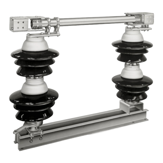
- Page 1 COLE TYPE L Copper Center Break Disconnect Switch For 8.3 – 72.5 kV Ratings INSTALLATION & INSTRUCTION MANUAL...
- Page 2 Page I The Quality Name in High Voltage Switching...
- Page 3 Page II The Quality Name in High Voltage Switching Safety Information...
- Page 4 The Quality Name in High Voltage Switching LIMITED WARRANTY Southern States, LLC (“SSLLC”) warrants only to the Warranty Holder (hereinafter defined as the “End User” or the “Immediate Purchaser”, as applicable, pursuant to the terms and conditions of this Limited Warranty as set forth below), that the Product identified below will, upon shipment, be free of defects in workmanship and material for the applicable Warranty Period.
- Page 5 Page IV The Quality Name in High Voltage Switching Southern States, LLC Equipment Receipt, Installation, Use, Operation and Maintenance Terms (“Terms of Use”)
- Page 6 Page V The Quality Name in High Voltage Switching...
- Page 7 Page VI The Quality Name in High Voltage Switching Type L 8.3 – 72.5 kV...
-
Page 8: Table Of Contents
Page VII The Quality Name in High Voltage Switching Table of Contents Chapter Page Table of Contents ..........................VII List of Tables and Figures ......................VIII Summary & Introduction ........................1 Summary ............................1 Important ............................1 Introduction ............................ 2 Ratings ............................ -
Page 9: List Of Tables And Figures
Page VIII The Quality Name in High Voltage Switching List of Tables and Figures Tables Page Table 1: Ratings Table ........................3 Table 2: Recommended Tools and Torque Values ................6 Table 3: Recommended Installation and Maintenance Table ............16 Figures Page Figure 1: Type L 69kV, 1600 amp ..................... -
Page 10: Summary & Introduction
The sales contract contains the entire obligations of Southern States. The Warranty contained in the contract between the parties is the sole warranty of Southern States. Any statements contained herein do not create new warranties or modify the existing warranty. -
Page 11: Introduction
Page 2 of 17 Summary & Introduction Introduction The Southern States, Cole Type L outdoor side break switches are available in ratings from 8.3kV through 72.5 kV and through 2000 amperes. The Type L is suitable for all types of outdoor disconnecting and sectionalizing service and may be mounted horizontally upright, horizontally underhung, vertically, or angularly. -
Page 12: Ratings
Page 3 of 17 Summary & Introduction Ratings Table 1: Ratings Table RATINGS Maximum Voltage Rating (kV) 15.5 48.3 72.5 BIL (kV) ADDITIONAL RATINGS Rated Power Frequency 60 Hz Continuous Current 1200A 2000A Short-Time Symmetrical Withstand (3 Sec.) 38 kA RMS 50 kA RMS Peak Withstand 99 kA... -
Page 13: Product Description
Page 4 of 17 Product Description Product Description Typical Disconnect Switch In general, installing a disconnect switch consists of the following: Mounting the insulators (F) to the switch base (A) • Mounting the live parts (B) to the insulators • Mounting the switch base (A) to the structure •... -
Page 14: Receiving, Handling & Storage
Page 5 of 17 Receiving, Handling & Storage Receiving, Handling & Storage Unpacking Unpack the equipment and check for damages or material shortages immediately. The bill-of-material from the Unit Assembly (switch) and Operating Mechanism drawings should be used for this purpose. If damage or a shortage is noted, file a claim immediately with the carrier and contact the factory. -
Page 15: Installation & Adjustment Procedures
Page 6 of 17 Installation & Adjustment Procedures Installation & Adjustment Procedures Recommended Tools & Values Table 2: Recommended Tools and Torque Values Recommended Tools Recommended Torque Values Type Sizes Bolt/Nut size Torque (Ft-lb) Hand Wrenches 15/16”, 3/4", 50 (S. Steel) 1/2”... -
Page 16: Preferred Switch Assembly Method
Page 7 of 17 Installation & Adjustment Procedures Preferred Switch Assembly Method: If Disconnect switch is shipped assembled on insulators, ignore steps 3 and 4 (below). 1. DO NOT CHANGE any factory setting unless directed to do so in this manual. 2. - Page 17 Page 8 of 17 Installation & Adjustment Procedures 5. If the switch has been assembled on the ground, at this time mount it on the structure, lifting by the switch base only. Refer to the Op. Mech. Drawing; there may be differences in the poles that require that they be mounted in specific locations.
-
Page 18: Operating Mechanism
Page 9 of 17 Installation & Adjustment Procedures Operating Mechanism (See Operating mechanism drawings provided for details): 1. Lay out all op-mech parts and check them against the Operating Mechanism drawing bill- of-material. 2. To ensure that the bearing stops do not interfere with switch adjustments, loosen each open/close bearing stop and slide them out of the way. -
Page 19: Final Switch Adjustments (Tuning)
Page 10 of 17 Installation & Adjustment Procedures Final Switch Adjustments (Tuning): 1. The operating mechanism is intended to fully open and fully close the disconnect switch by rotating the vertical operating pipe approximately 180 using an operator (manual or electrical). - Page 20 Page 11 of 17 Installation & Adjustment Procedures Worm gear operator (SEGO – Safety Enhanced Gear Operator) (Optional) 3.1 The weight of the vertical operating pipe should be supported by pipe collar by maintaining the ¼”-3/8” gap. 3.2 When the switch is properly adjusted the operator handle should hang freely in both the open and closed positions to permit the use of the customer supplied padlock.
- Page 21 Page 12 of 17 Installation & Adjustment Procedures 4.1.1 The switch is in the fully closed position when the centerline of the male blade assembly is aligned with the centerline of the Female Blade Assembly. 4.2 Set the adjustable arm to the preliminary setting on the Operating Mechanism drawing, adjustment may be necessary to achieve proper operation.
- Page 22 Page 13 of 17 Installation & Adjustment Procedures Loosen Bolts for Adjustment Figure 8: Adjustable Arm Assembly 5.9 Final Check: 5.9.1 Once all final adjustments are complete, be sure that all nuts are tightened to their specified torque (Refer to Table 2). 5.9.2 Apply a minimal amount of grease to the point of each piercing bolt and then tighten the bolt until it pierces the pipe wall.
-
Page 23: Changing Disconnect Opening Direction
The following are instructions for making field modifications to the opening direction of the disconnect switch if it is determined that it is necessary. If parts or assistance are required please contact your Local Representative or Southern States Service Division, contact information provide on the back page. - Page 24 Page 15 of 17 Installation & Adjustment Procedures operator will have to be changed to achieve proper rotation. Please contact representative. 3. Leave the operator in the starting position as originally shown on the operating mechanism drawing. 4. To achieve CLOCKWISE handle rotation to OPEN you must attach the adjustable arm 180 degrees from its original setup.
-
Page 25: Recommended Inspection Maintenance
Recommended Inspection Maintenance Recommended Inspection Maintenance Southern States’ disconnect switches are designed to operate with minimum maintenance. While disconnecting switches are not readily serviced at frequent intervals, periodic inspection is important for satisfactory operation and maximized overall life. Frequency of inspection and maintenance depends on the installation site, weather, atmospheric conditions, experience of operating personnel, and any special operation requirements. -
Page 26: Patrolling Inspection (6 Months)
Page 17 of 17 Recommended Inspection Maintenance Patrolling Inspection (6 Months) The patrolling inspection is a largely visual inspection on an energized unit in service. The frequency of the inspection is determined by the local conditions and policies of the owner of the equipment. Inspect the insulators for breaks, cracks, burns, or cement deterioration. - Page 28 30 Georgia Avenue Hampton, Georgia 30228 Phone: 770-946-4562 Fax: 770-946-8106 E-mail: support@southernstatesllc.com http://www.southernstatesllc.com ©2021 Southern States, LLC IB-107-Cole L-Rev6 02182021 Printed U.S.A.
Need help?
Do you have a question about the COLE L and is the answer not in the manual?
Questions and answers