
Subscribe to Our Youtube Channel
Related Manuals for Moxa Technologies AirWorks AWK-3251A-M12-RCC Series


Summary of Contents for Moxa Technologies AirWorks AWK-3251A-M12-RCC Series
- Page 1 AWK-3251A-M12-RCC Series Quick Installation Guide Moxa AirWorks Version 1.0, September 2022 Technical Support Contact Information www.moxa.com/support 2022 Moxa Inc. All rights reserved. P/N: 1802032510010 *1802032510010*...
-
Page 2: Hardware Setup
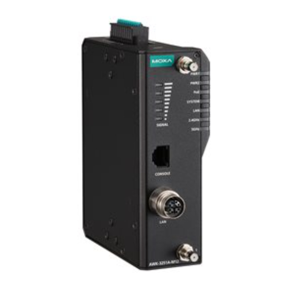
Overview The AWK-3251A-M12-RCC Series is an industrial-grade AP/Client with IEEE 802.11ac Wave 2 technology. This Series features concurrent dual-band Wi-Fi data transmissions up to 400 Mbps (2.4 GHz mode) and 867 Mbps (5 GHz mode) simultaneously, meeting the speed and flexibility requirements for industrial applications. - Page 3 Panel Layout of the AWK-3251A-M12-RCC Series 1. Grounding screw (M5) 11. Screw holes for wall-mounting 2. Terminal blocks for PWR1, PWR2, relay, DI 1 and DI 2 12. DIN-rail mounting kit 3. Reset button 13. Cable holder screw 4. Antenna connector 2 5.
-
Page 4: Mounting Dimensions
Mounting Dimensions DIN-rail Mounting When shipped, the metal DIN-rail mounting kit is fixed to the back panel of the AWK-3251A-M12-RCC. Mount the AWK-3251A-M12-RCC on to a corrosion-free mounting rail that adheres to the EN 60715 standard. STEP 1: STEP 2: Insert the upper lip of the DIN-rail Press the AWK-3251A-M12-RCC kit into the mounting rail. -
Page 5: Wall Mounting (Optional)
To remove the AWK-3251A-M12-RCC from the DIN rail, do the following: STEP 1: Pull down the latch on the DIN- rail kit with a screwdriver. STEP 2 & 3: Slightly pull the AWK-3251A- M12-RCC forward and lift it up to remove it from the mounting rail. -
Page 6: Wiring Requirements
STEP 3: Once the screws are fixed into the wall, insert the four screw heads through the large opening of the keyhole-shaped apertures, and then slide the AWK-3251A-M12-RCC downwards, as indicated to the right. Tighten the two screws for added stability. WARNING •... - Page 7 NOTE Do not run signal or communications wiring and power wiring in the same wire conduit. To avoid interference, wires with different signal characteristics should be routed separately. • You can use the type of signal transmitted through a wire to determine which wires should be kept separate.
-
Page 8: Terminal Block Pin Assignment
Grounding the AWK-3251A-M12-RCC Grounding and wire routing help limit the effects of noise due to electromagnetic interference (EMI). Run the ground connection from the ground screw to the grounding surface prior to connecting devices. ATTENTION This product is intended to be mounted to a well-grounded mounting surface, such as a metal panel. -
Page 9: Wiring The Redundant Power Inputs
Definition DC Power Input 1 DC Power Input 2 Relay Output Digital Input 1 Digital Input GND Digital Input 2 Digital Input GND Wiring the Redundant Power Inputs The first two pairs of contacts of the 10-contact terminal block connector on the AWK-3251A-M12-RCC’s top panel are used for the AWK-3251A-M12-RCC’s two DC inputs. -
Page 10: Wiring The Relay Contact
Wiring the Relay Contact The AWK-3251A-M12-RCC has one relay output, which consists of the two contacts of the terminal block on the AWK-3251A-M12-RCC’s top panel. Refer to the previous section for detailed instructions on how to connect the wires to the terminal block connector, and how to attach the terminal block connector to the terminal block receptor. -
Page 11: Communication Connections
Communication Connections 10/100/1000BaseT(X) Ethernet Port Connection The 10/100/1000BaseT(X) ports located on the AWK-3251A-M12-RCC’s front panel are used to connect to Ethernet-enabled devices. MDI/MDI-X Port Pinouts 1000BaseT 10/100BaseT 10/100BaseT MDI/MDI-X MDI-X DA– DB– – – DD– – – – – – –... -
Page 12: Specifications
Color State Description System startup completed and is operating Green normally. LAN port’s 1000 Mbps link is active. Blinking Data is being transmitted at 1000 Mbps. Green (3 Hz) LAN port’s 1000 Mbps link is inactive. LAN port’s 10/100 Mbps link is active. Blinking Data is being transmitted at 10/100 Mbps. -
Page 13: Software Setup
ATTENTION The AWK-3251A-M12-RCC is NOT a portable mobile device and should be located at least 50 cm away from the human body. The AWK-3251A-M12-RCC is NOT designed for the general public. To ensure that your AWK-3251A-M12-RCC wireless network is safe and configured correctly, consult a well-trained technician to assist with the installation process. - Page 14 Step 1: Select a suitable power source and plug in the AWK. • The AWK can be powered by DC power ranging from 12 VDC to 48 VDC or by a PoE PSE via an Ethernet connection. • Step 2: Connect the AWK to the notebook or PC via the AWK’s LAN port.
- Page 15 Step 5: Choose your country or region. • Select your country or region from the drop-down list and click NEXT. Step 6: Create a user account and password. • Enter the username, password, and email address for your user account and click CREATE. NOTE The username and password are case-sensitive.
-
Page 16: First-Time Quick Configuration
After creating your account, you will be automatically redirected to the login screen. Step 7: Log in to the device. • Enter your username and password and click LOG IN. The device will start initializing, this may take several seconds. Once the warning message has disappeared, you can log in using your username and password. - Page 17 AP/Client Mode Configuring the AWK as an AP Step 1: Set the operation mode of the AWK to AP mode. • Go to Wi-Fi Wireless Settings and select AP from the Operation Mode drop-down list. • Step 2: Set up the AWK as an AP. Click the ADD icon to create a new SSID.
- Page 18 On the settings page, configure the SSID Status, SSID, RF Band, RTS/CTS Threshold, and Transmission Rate for the 5 GHz or 2.4 GHz band. When finished, click NEXT. On the second SSID Settings screen, configure the SSID Broadcast Status and Security type. From here, you can also copy the configuration over to the second SSID.
- Page 19 Configuring the AWK as a Client Step 1: Set the operation mode of the AWK to Client mode. • Go to Wi-Fi Wireless Settings and select Client from the Operation Mode drop-down list, set the SSID, and click Apply. For more detailed configurations, refer to the AWK-3251A-M12-RCC User Manual.
- Page 20 Configuring the AWK as a Master Step 1: Set the operation mode of the AWK to Master mode. • Go to Wi-Fi Wireless Settings and select Master from the Operation Mode drop-down list. Step 2: Set up the AWK as a Master. •...
- Page 21 On the second SSID Settings screen, configure the SSID Broadcast Status and Security type. From here, you can also copy the configuration over to the second SSID. When finished, click CONFIRM. Configuring the AWK as a Slave Step 1: Set the operation mode of the AWK to Slave mode. •...
-
Page 22: Fcc/Ic Statements
Certifications FCC/IC Statements Federal Communication Commission Interference Statement This equipment has been tested and found to comply with the limits for a Class A digital device, pursuant to Part 15 of the FCC Rules. These limits are designed to provide reasonable protection against harmful interference in a residential installation. - Page 23 Manufacturer Item Model name Type 2.4GHz Gain 5GHz Gain MOXA ANT-WDB-ANM-0306 Dipole MOXA ANT-WDB-ANM-0502 Dipole 4.62 1.41 MOXA ANT-WDB-ARM-02 Dipole 2.04 0.38 MOXA ANT-WDB-ARM-0202 Dipole MOXA ANT-WSB-AHRM-05-1.5m Dipole 5.00 MOXA MAT-WDB-CA-RM-2-0205 Dipole MOXA MAT-WDB-DA-RM-2-0203-1m Dipole 2.45 2.72 MOXA MAT-WDB-PA-NF-2-0708 Panel 7.63 8.77 MOXA...
-
Page 24: Ncc Statements
Canada, Innovation, Science and Economic Development Canada (ISED) Notices This device contains licence-exempt transmitter(s)/receiver(s) that comply with Innovation, Science and Economic Development Canada’s licence-exempt RSS(s). Operation is subject to the following two conditions: This device may not cause interference. This device must accept any interference, including interference that may cause undesired operation of the device.
Need help?
Do you have a question about the AirWorks AWK-3251A-M12-RCC Series and is the answer not in the manual?
Questions and answers