PSI SpectraPen LM 510 Series Instruction Manual
Hide thumbs
Also See for SpectraPen LM 510 Series:
- Manual and user manual (43 pages) ,
- Instruction manual (34 pages)
Table of Contents
Advertisement
Quick Links
Advertisement
Table of Contents

Related Manuals for PSI SpectraPen LM 510 Series


Summary of Contents for PSI SpectraPen LM 510 Series
- Page 2 This document and its parts can be copied or provided to a third party only with the express permission of PSI. The contents of this manual have been verified to correspond to the specifications of the device. However, deviations cannot be ruled out.
-
Page 3: Table Of Contents
ABLE OF CONTENT Information before using SpectraPen device ..................5 General Description ..........................5 Technical Specification ..........................7 Device Description ..........................8 List of equipment and customer information ....................9 Care and maintenance ..........................9 Getting started ............................ 10 Dark spectrum calibration .......................... 10 Measurement ............................. -
Page 4: Information Before Using Spectrapen Device
NFORMATION BEFORE USING PECTRA EN DEVICE Read this manual carefully before operating the device. If you are not sure about something in the manual, contact the manufacturer for clarification. By accepting the device, the customer agrees to follow the instructions in this guide. Always follow corresponding manuals while working with the SpectraPen device or doing the maintenance. - Page 5 SpectraPen measures: Scope - quantitative light intensity at different wavelengths Irradiance spectrum [µW.cm Photon flux density spectrum [µmol.m Light Meter - absolute light intensity at defined range of wavelengths of the electromagnetic spectrum Irradiance [W.m ] in user defined range of the electromagnetic spectrum Photon flux density [µmol.m ] in user defined range of the electromagnetic spectrum Illuminance [Lux] - total luminous flux incident on a surface, per unit area...
-
Page 6: Technical Specification
2.1 T ECHNICAL PECIFICATION 340 nm – 790 nm (LM 510 UVIS) Spectral range 640 nm – 1050 nm (LM 510 NIR) Spectral response half width 9 nm FWHM bandwidth 7 nm Wavelength reproducibility +/- 0.5 nm Spectral Straylight -30 dB Set automatically Integration time From 5 ms to 10 s... -
Page 7: Device Description
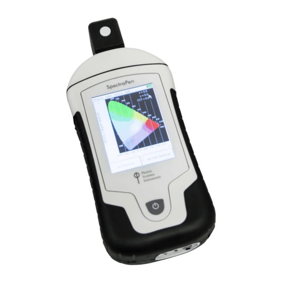
EVICE ESCRIPTION Fig. 2 Device description Cosine corrector The optical sensor of the SpectraPen and the cosine corrector, is placed inside of the black box positioned on the front panel which protects the optics from dirt or moisture. The sensor is covered with a teflon ring placed either on top (horizontal position) or in front (vertical position) of the optical head depending on the device version. -
Page 8: List Of Equipment And Customer Information
Do not keep the battery at full charge for long periods of time. Allow for it to discharge. • High temperatures shorten battery life. • If the battery can no longer be charged, please contact PSI for replacement battery and installation instructions. Page | 9... -
Page 9: Getting Started
ETTING STARTED Switch on the device by pressing the Power button and follow next steps to perform the measurements. In case the device battery is not charged connect the SpectraPen to the PC or to USB adaptor (not included) via the USB cable and charge the battery. Before any parameters are measured with SpectraPen device dark spectrum scan must be performed. -
Page 10: Measurement
In case surrounding temperature is rapidly changed during the calibration step or during the measurement, the SpectraPen will automatically ask for new dark spectrum calibration. 4.2 M EASUREMENT SpectraPen can calculate a number of parameters that are derived from measurements of: •... - Page 11 Light meter Light meter function is used for measurements of absolute light intensity at defined range of wavelengths (Fig. 7). Photon flux density measurements display units in micromoles per square meter per second, irradiance measurements are displayed in Watts per square meter and illuminance measurements are displayed in units of Lux.
-
Page 12: Menu Description
ENU DESCRIPTION Measure This option is described in the Chapter 4.2. Data • Browse (Fig. 9) – displays data browse dialog box. The user can browse the list of stored data, select the set of data files and view the light spectra in Scope mode. Color classification of each data file helps the user to discriminate between individual measurements. - Page 13 Please note that the wavelength range setting applies only for light meter. Light intensity measured in selected range is shown only on the SpectraPen display. The device saves to the memory the whole spectrum and light intensity calculated from the whole spectrum. The wavelength range setting is not active for Illuminance.
-
Page 14: Pc Communication
Help • About…- information about the device, hardware and software version (Fig. 13). Fig. 13 Information about the device. 6 PC COMMUNICATION 6.1 USB CONNECTION SpectraPen comes with the USB cable that is required for charging of the Li-ion battery and can also be used for data transfer to the PC after completion of measurements. -
Page 15: Driver Installation
To connect SpetraPen with your computer please follow steps below in Fig. 14 Fig. 14 How to connect SpectraPen with PC. A) connector on the SpectraPen device. B) Portion of the USB cable with pins. C – E) Position the cable horizontally and line up the green circled parts of the cable and the connector, plug in the inlet and screw the securing screw. - Page 16 Navigate through System and security, System to Device manager (Fig. 16) • Connect the SpectraPen to the PC. You should see that PSI USB Device appears in the list. Right click on it and select Update Driver Software (Fig. 17) Fig.
-
Page 17: Spectrapen Software
• Installation of the driver is now complete (Fig. 19) In case this driver installation is not successful the driver may be downloaded directly from PSI websites www.psi.cz. Once the device is properly connected to the computer, the indicating icon appears on the SpectraPen device display Fig. 20. - Page 18 Fig. 21 Software registration. Please note that the serial (registration) number for the SpectraPen may be found in the file SN.txt, which is included on the enclosed USB flash disk. Please Note: it is not possible to download data from the SpectraPen device without software registration. 3.
- Page 19 Fig. 23 SpectraPen connected. Fig. 24 SpectraPen not connected. Page | 20...
-
Page 20: Software Menu
7.2 S OFTWARE MENU MENU: File Load Loads previously saved data files. Save Saves data to hard disc. Export Exports data in .txt format. Export to JSON Exports data in JavaScript Object Notation. Close Closes the current experiment. Close All Closes all open experiments. -
Page 21: Data Transfer And Visualization
7.3 D ATA TRANSFER AND VISUALIZATION 1. After completion of measurement SpectraPen may be connected to PC for data download and further analysis. 2. Launch the SpectraPen software on the computer and connect the device. Go to Device> Connect. 3. To transfer your data from the SpectraPen device to your PC use the Download function. Select icon on left side of screen or go to File and select Load if you want to process data stored on PC. - Page 22 Fig. 30 Options for list of data. 8. In the graph marker feature is available, which enables display of the numeric values for wavelength and light irradiance for the selected wavelength of the scan (Fig. 31). Use the mouse to select the given point. In top right corner of the graph (red rectangle) is displayed exact value for the selected point on the x-axis and y-axis.
- Page 23 Fig. 32 Zoom function. 10. Select Irradiance tab to view the irradiance data stored either as µmol.m or per µW.cm . To change the units in which the spectra is displayed click on the unit icon as shown in Fig. 33. Fig.
- Page 24 11. To view the light meter data for the spectral scans acquired click on the unit icon as depicted by red arrow in Fig. 34. Irradiance and illuminance light meter numerical values for each scan are displayed as LUX, PAR or IRRADIANCE values (Fig. 34). Fig.
- Page 25 Fig. 36 Export of Irradiance spectrum. Computed Data – computed numeric values for Scope and Irradiance are exported for all measurements. The user can choose if only Scope numeric values or Irradiance numeric values are exported. For irradiance values, numeric data for Photon flux density and PAR in [µmol.m units, irradiance in µW.cm units and illuminance in LUX units are exported (Fig.
-
Page 26: Online Control
7.4 O NLINE CONTROL Menu Online Control This function can be used for remote - online control of the SpectraPen device after connection with the PC. Online control enables to make changes in device setting and also perform remote measurement using PC. Select: Menu >... -
Page 27: Firmware Update
Settings (Fig. 40) Here the following functions may be set up for remote operation of the SpectraPen: • Time synchronization of the device and PC • GPS built-in module activation (more information about the GPS module in chapter 8) • Averaging of measurement (1 –... -
Page 28: Gps Module
8 GPS MODULE SpectraPen device LM 510 has integrated GPS module which may be turned on during the measurement for mapping of the collected data to specific field position. When GPS module is turned on, the map coordinates will be automatically saved with all collected data and will be downloaded during data download. - Page 29 Fig. 43 Data with GPS coordinates. Page | 30...
-
Page 30: Warranty Terms And Conditions
If at any time within this warranty period the instrument does not function as warranted, return it and the manufacturer will repair or replace it at no charge. The customer is responsible for shipping and insurance charges (for the full product value) to PSI. The manufacturer is responsible for shipping and insurance on return of the instrument to the customer. -
Page 31: Appendix
PSIindex – name of the index in the SpectraPen software and in exported data • PSI test index – full name of the index (not showed) • Scope[600nm]/ Scope[500nm] – equation for calculation; calculated from 500 and 600 nm of Scope spectra Fig. -
Page 32: Function Description
Fig. 45 New index. 11.1.1 F UNCTION DESCRIPTION Different mathematical functions can be used in SpectraPen software syntax to create new custom formulas. min, max - min(value1, value2) value1 - number, variable, function value2 – number, variable, function - only one value can be function! min(array) array –... - Page 33 example1: sqrt(5) example2: sqrt(Scope[760nm]) example3: sqrt(max(Scope[550nm], Scope[480nm])) example4: sqrt(((5+4)*4) + 6) ____________________________________________________________________________ - specified number raised to the specified power value^power value – number, variable, function power – number, variable, function example1: Irradiance[760nm]^ Irradiance[550nm] example2: min(Irradiance[760nm], Irradiance[550nm])^max(Irradiance[435nm], Irradiance[430nm]) example3: Transmitance[760nm]^0.5 ___________________________________________________________________________ integral express the area under the curve of a graph of the function in the interval...
-
Page 34: List Of Figures
Fig. 14 How to connect SpectraPen with PC..............................16 Fig. 15 Control panel....................................16 Fig. 16 System window....................................17 Fig. 17 PSI USB device ....................................17 Fig. 18 Choose the driver from the USB disc............................... 17 Fig. 19 Complete installation..................................18 Fig.
Need help?
Do you have a question about the SpectraPen LM 510 Series and is the answer not in the manual?
Questions and answers