Table of Contents
Advertisement
Quick Links
December 2010
Arrow.com.
Downloaded from
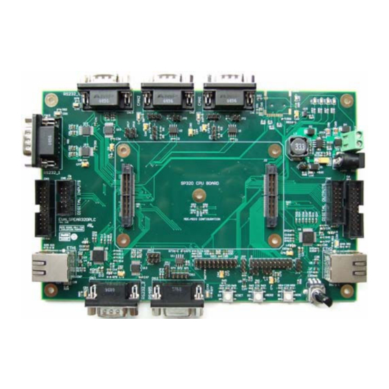
EVALSPEAr320PLC evaluation board for the SPEAr320
Introduction
This user manual describes the implementation of the SPEAr320PLC evaluation board
(order code: EVALSPEAr320PLC). This evaluation board can be used to evaluate the
SPEAr320 microprocessor with a variety of devices and especially its Media Independent
Interface (MII) Automation mode.
The EVALSPEAr320PLC evaluation board kit comprises two boards:
CPU board
G
MII mode application board
G
The SPEAr320 microprocessor is mounted on the CPU board that is plugged on the MII
mode application board.
The application board is equipped with two Ethernet, three RS-232, one RS-485, two CAN,
SPI, I²C communication interfaces and MicroSD card socket with SDIO interface. There are
also two general-purpose push-buttons, four LEDs, a temperature sensor and a
potentiometer available for the user interface.
The application board also includes digital input/output serial/parallel connectors with a
pinout compatible to many existing evaluation boards from ST:
Digital input serial: STEVAL-IFP007V1
G
Digital input parallel: STEVAL-IFP004V1 and STEVAL-IFP008V1
G
Digital output serial: STEVAL-IFP009V1
G
Digital output parallel: STEVAL-IFP002V1, STEVAL-IFP001V1 and STEVAL-IFP006V1
G
The application board can be powered using a standard DC power supply (7 V to 30 V DC)
or directly using a 24 V DC industrial mains supply.
Figure 1.
SPEAr320 MII mode application board
Doc ID 16542 Rev 4
UM0842
User manual
1/50
www.st.com
Advertisement
Table of Contents

Subscribe to Our Youtube Channel
Related Manuals for ST EVALSPEAr320PLC


Summary of Contents for ST EVALSPEAr320PLC
-
Page 1: Figure 1. Spear320 Mii Mode Application Board
Introduction This user manual describes the implementation of the SPEAr320PLC evaluation board (order code: EVALSPEAr320PLC). This evaluation board can be used to evaluate the SPEAr320 microprocessor with a variety of devices and especially its Media Independent Interface (MII) Automation mode. -
Page 2: Table Of Contents
Contents UM0842 Contents CPU board features ......... . 6 CPU board block diagram . - Page 3 UM0842 Contents Digital output parallel connector (CN6) ......20 Ethernet RJ-45 connectors (CN7 and CN8) ..... . . 20 General-purpose ADC connector (CN9) .
- Page 4 Application board layout ........... . 8 Figure 5. EVALSPEAR320PLC board with digital input and digital output cards ....11 Figure 6.
- Page 5 UM0842 List of tables List of tables Table 1. MII addresses of the Ethernet PHYs (U5 and U6) ....... 10 Table 2.
-
Page 6: Cpu Board Features
CPU board features UM0842 CPU board features SPEAr320 embedded MPU Up to 2 Gbit DDR2 333 MHz (standard 128 Mbytes) Up to 16 Mbyte Serial Flash memory (standard 8 Mbytes) Two USB 2.0 full host port channels One USB 2.0 host device port One serial port (up to 115 baud) JTAG Debug ports For more information about the CPU board, please refer to... -
Page 7: Application Board Features
UM0842 Application board features Application board features 2 x Ethernet RJ-45 connectors (ST802RT1A) 2 x CAN DB9 plug connectors 3 x RS-232 DB9 plug connectors (ST3232EBTR) 1 x RS-485 DB9 socket connector (ST3485EBDR) Digital input connectors (parallel and serial) compatible with STEVAL-IFP007V1, STEVAL-IFP008V1 and STEVAL-IFP004V1 evaluation boards Digital output connectors (parallel and serial) compatible with STEVAL-IFP009V1, STEVAL-IFP001V1, STEVAL-IFP002V1 and STEVAL-IFP006V1 evaluation boards... -
Page 8: Application Board Layout
Application board layout UM0842 Application board layout Figure 4. Application board layout RS232_1/ Digital UART1 input serial Digital input parallel Ethernet1 CN14 RS232_0/ RS232_2/ UART0 UART2 SPEAr320 Reset CPU board CN12 RS485/ UART2 CAN1 CN10 GPIO, I2C connector connector CAN0 Tem perature sensor CN16... -
Page 9: Getting Started
Unpacking Warning: This board contains static sensitive devices. The EVALSPEAr320PLC evaluation board is shipped in protective anti-static packaging. Do not submit the board to high electrostatic potentials, and follow good practices for working with static sensitive devices. Wear an anti-static wristband. Wearing a simple anti-static wristband can help prevent ESD from damaging the board. -
Page 10: Configuration
Configuration UM0842 Configuration Ethernet There are two Ethernet PHYs (U5 and U6) available on the board that are connected through the media independent interfaces (MII) to the Ethernet MACs on the CPU board processor. By default the MII addresses of the Ethernet PHYs are selected as shown in Table Table 1. -
Page 11: Digital Input / Digital Output Connectors
Digital input / digital output connectors The digital input and digital output connectors are used to extend the EVALSPEAR320PLC board with the industrial input and output cards. The input sensors (for example, proximity switches) of the controlled industrial process are normally decoupled and connected by the current limiters based on the CLT and SCLT devices of the microcontroller. -
Page 12: Controller-Area Network Bus
8/16 input channel current limiter based on SCLT3-8, STEVAL-IFP007V1 Controller–area network bus The EVALSPEAR320PLC evaluation board supports two channels of CAN2.0A/B compliant controller–area network (CAN) bus communication based on a 3.3 V CAN transceiver. High- speed mode, standby mode and slope control mode are available and can be selected by setting jumper JP1 for CAN0 and jumper JP4 for CAN1. -
Page 13: Rs-232 And Rs-485 Transceivers
UM0842 Configuration Table 5. CAN1 transceiver settings Jumper Description Configuration 1 2 3 CAN1 transceiver works in standby mode when JP4 is set. CAN1 transceiver works in high-speed mode when JP4 is set 1 2 3 (Default). CAN1 transceiver works in slope control mode when JP4 is 1 2 3 open. -
Page 14: Power Supply
Connecting the +5 V voltage adapter (delivered in the EVALSPEAr320PLC package) to the J11 power voltage connector on the CPU board. Connecting a 7 V to 30 V DC power source (not included in the EVALSPEAr320PLC package) to either connectors CN17 or CN18 on the application board. -
Page 15: Temperature Sensor
UM0842 Configuration Table 8. U16 DC/DC converter jumpers Jumper Description Configuration Can be used to disconnect the +5 V delivered from the DC/DC JP14 converter U16 (Default - loaded). 1 2 3 For L7986A the jumper must be set (Default). JP15 (SMD resistor) -
Page 16: General-Purpose Buttons (B1 And B2)
Configuration UM0842 Table 9. ADC conversion settings Jumper Description Configuration Connects the +2.5 V ADC evaluation board ADC supply 1 2 3 voltage to the ADC_VREFP pin of the CPU board (Default). Connects the external ADC application supply voltage to the 1 2 3 ADC_VREFP pin of the CPU board. -
Page 17: Reset Button
5.12 MicroSD card The MicroSD card connector connected to the SDIO interface of the EVALSPEAR320PLC is available on the board. MicroSD card detection is managed by the standard SDIO signal SDCD when the card is inserted. In order to power-up the MicroSD card properly, it is necessary to detect the card insertion and then to enable the single channel power switch U15 by means of PL_GPIO61 (active low). -
Page 18: Connectors
Connectors UM0842 Connectors CAN DB9 plug connectors (CN1 and CN2) Figure 7. CAN DB9 plug connectors pinout Table 11. CAN DB9 plug connectors description Description Description 1, 4, 8 CANH CANL 3, 6 Chassis Optional supply voltage (+3.3 V or +5.0 V) Digital input serial connector (CN3) This connector enables connection of industrial output card STEVAL-IFP007V1. -
Page 19: Digital Output Serial Connector (Cn4)
UM0842 Connectors Digital output serial connector (CN4) This connector enables connection of industrial output card STEVAL-IFP009V1. Figure 9. Digital output serial connector pinout 8 10 12 14 16 18 20 11 13 15 17 19 Table 13. Digital output serial connector description Signal Signal Signal... -
Page 20: Digital Output Parallel Connector (Cn6)
Connectors UM0842 Digital output parallel connector (CN6) This connector enables connection of industrial output cards: STEVAL-IFP002V1, STEVAL- IFP001V1, STEVAL-IFP006V1. Figure 11. Digital output parallel connector (CN6) pinout 8 10 12 14 11 13 Table 15. Digital output parallel connector (CN6) description Signal Signal Signal... -
Page 21: General-Purpose Adc Connector (Cn9)
UM0842 Connectors General-purpose ADC connector (CN9) Figure 13. General-purpose ADC connector (CN9) pinout 8 10 12 14 16 18 20 11 13 15 17 19 Table 17. General-purpose ADC connector (CN9) description Signal Signal Signal Signal ADC VREF Negative or AIN4 GND by JP8 AIN2... -
Page 22: Rs-485 Db9 Socket And Header Connector (Cn11 And Cn12)
Connectors UM0842 RS-485 DB9 socket and header connector (CN11 and CN12) Figure 15. RS-485 DB9 socket connector CN11 pinout Table 19. RS-485 DB9 socket connector CN11 description Description Description +5.0 V Figure 16. RS-485 header connector CN12 pinout Table 20. RS-485 header connector CN12 description Description Description... -
Page 23: Rs-232/Uart2 Db9 Plug Connector (Cn14)
UM0842 Connectors Table 21. RS-232/UART0 DB9 plug connector (CN13) description Description Description UART0_DCD UART0_DSR UART0_RX UART0_RTS UART0_TX UART0_CTS UART0_DTR UART0_RI 6.11 RS-232/UART2 DB9 plug connector (CN14) Figure 18. RS-232/UART2 DB9 plug connector (CN14) pinout Table 22. RS-232/UART2 DB9 plug connector (CN14) description Description Description NC (R79 can interconnect this pin with... -
Page 24: Microsd Card Connector (Cn16)
Connectors UM0842 Table 23. RS-232/UART1 DB9 plug connector (CN15) description Description Description NC (R81 can interconnect this pin with Connected to pin 4 pins 4 and 6) UART1_RX Connected to pin 8 UART1_TX Connected to pin 7 Connected to pin 6 6.13 MicroSD card connector (CN16) Figure 20. -
Page 25: Power Supply Connectors (Cn17 And Cn18)
UM0842 Connectors 6.14 Power supply connectors (CN17 and CN18) Figure 21. Power supply connector Figure 22. Power supply connector CN18 diagram CN17 diagram Table 25. Power supply connector CN18 description Signal Signal 24 V DC Table 26. Power supply connector CN17 description Signal 24 V DC 6.15... -
Page 26: Table 27. 86-Pin Connector (J1) Description
Connectors UM0842 Table 27. 86-pin connector (J1) description (continued) Description Description Description MII1_COL MII1_CRS +5.0 V MII1_RXER SSP_CLK MII1_MDIO +5.0 V MII1_MDC SSP_MISO SSP_SS0 +5.0 V MII1_RXDV UART0_TX I2C_SCL / PL_GPIO4 UART2_TX SDAT1 / MicroSD card MII1_RXD2 data 1 UART0_RX I2C_SDA/ PL_GPIO5 UART2_RX UART0_DCD... - Page 27 UM0842 Connectors Table 28. 86-pin connector (J2) description (continued) Description Description Description SDCD / MicroSD card PL_GPIO63 detect PL_GPIO56 MII2_RXD0 MII2_TXEN SDAT3 / MicroSD card DIDO54 / PL_GPIO54 AIN5 data 3 LED3 / PL_GPIO58 MII2_TXD1 MII2_TXD3 PL_GPIO57 / MicroSD DIDO74 / PL_GPIO74 card over current LED4 / PL_GPIO64 DIDO79 / PL_GPIO79...
-
Page 28: Appendix A Cpu Board Hardware Description
CPU board hardware description UM0842 Appendix A CPU board hardware description CPU board layout Figure 24. CPU board layout (top view) Power supply (J11) Serial link JTAG (J3) USB Hosts (J2) USB Device (J1) Figure 25. CPU board layout (bottom view) 28/50 Doc ID 16542 Rev 4 Arrow.com. -
Page 29: Block Descriptions
UM0842 CPU board hardware description Block descriptions A.2.1 Dynamic memory subsystem The Dynamic memory subsystem is composed of three major parts: Memory chip The SPEAr320 MPU supports up to 256 Mbytes of memory. Place and route is provided for 2 chips but only one has been populated. The memory used is a Micron DDR2 device, its part number is MT47H64M16HR-3 and its size is 128 Mbits x 8 (16 Mbits x 8 x 8 banks). -
Page 30: Serial Interface
CPU board hardware description UM0842 The debug feature can be selected by setting Switch SW1 bits [2:1]. Table 29. Switch SW1 bits [2:1] Bit 2 Bit 1 Description No debug features available The ARM JTAG is connected to J4 Please refer to the documentation of the trace box manufacturer for more information on the ETM interface (www.lauterbach.com, www.agilent.com, www.yokogawa.com). -
Page 31: Cpu Board Switch And Jumper Settings
’1’. Bits 3, 4, 5 and 6 allow you to set the Functional configuration. The default configuration is Configuration 3. For other configurations, please refer to the SPEAr320 user manual available on www.st.com/spear. Doc ID 16542 Rev 4 31/50 Arrow.com. -
Page 32: Switch 2 Settings
CPU board hardware description UM0842 A.3.2 Switch 2 settings Table 33. Switch 2 settings Boot from SW2-1 SW2-2 SW2-3 SW2-4 SW2-5 SW2-6 SW2-7 SW2-8 USB_BOOT ETH (parameter from I2C ROM) ETH (parameter from SPI ROM) Serial NOR (default setting) Parallel NOR 8 (EMI with ACK) Parallel NOR 16 (EMI with ACK) Parallel NAND 8... -
Page 33: Jumpers & Connectors
A.3.3 Jumpers & connectors The jumpers and connectors numbered below refer to the CPU board schematics (available from your local ST representative). Sheet 4 Connector J3 is a standard 20-pin 2.54 mm connector used for JTAG connections. Jumper J5 enables the power supply to the Real Time Clock block. -
Page 34: Cpu Board Expansion Connectors
CPU board hardware description UM0842 CPU board expansion connectors The CPU board includes two 86-pin connectors (one on each side) used to extend the board with the SPEAr320 application boards. Table 34. CPU board extension connector J12 Description Description Description SSP_MOSI MII1_RXD0 +5.0 V... -
Page 35: Table 35. Cpu Board Extension Connector J13
UM0842 CPU board hardware description Table 35. CPU board extension connector J13 Description Description Description LED1 / PL_GPIO47 PL_GPIO76 MII2_RXER +3.3 V DIDO53 / PL_GPIO53 AIN4 LED2 / PL_GPIO49 MII2_RXD2 MII2_RXDV PL_GPIO63 SDCD / MicroSD card detect PL_GPIO56 MII2_RXD0 MII2_TXEN SDAT3 / MicroSD card data DIDO54 / PL_GPIO54 AIN5... -
Page 36: Cpu Board Bill Of Materials
CPU board hardware description UM0842 CPU board bill of materials Table 36. List of components Item Qty. Reference Part Footprint Description Part number C1, C2, C3, C4, C5, C6, C7, C8, C9, C10, C11, C12, C13, C14, C15, C16, C17, C18, C19, C20, C21, C22, C23, C24, C25, C26, C27, C28, C29, C30, C31,... -
Page 37: Table 36. List Of Components
UM0842 CPU board hardware description Table 36. List of components (continued) Item Qty. Reference Part Footprint Description Part number SCR TS420- Switching Diode/600/4 A/ TS420-600B DPAK 200 mW/DPAK/RoHS (STm) D5, D6, D7, D8 and D9 GREEN 0805P LED/GREEN/SLED0805 WURTH Bead/3 A/120 Ohm/ FB1 and FB2 0805 742792023... - Page 38 CPU board hardware description UM0842 Table 36. List of components (continued) Item Qty. Reference Part Footprint Description Part number NPN Transistor/50 Q2 and Q3 SOT23 V/50 V/5/ 0.5 A/ PDTD123Y 0.25 W/SOT23 121 kOhm Resistor/121 kOhm/NO/ R1 and R53 0805 1%/SR0805/RoHS R2, R3, R4, R5, R6 and Resistor/100 Ohm/NO/...
- Page 39 Reset IC/3 V/ SOT143-4/ STM811SW16F STM811 SOT143-4 RoHs (STm) Backup BATT BR2032 Battery/3 V/220 mAh/ BR2032 battery-holder-cr2032/VH ST LD1117 LDO/15 Vmax/2.5 V/0.8 A/ LD1117S25TR SOT223 S25TR 2%/SOT223/RoHs (STm) DDR2 DDR3 Switching VFQFPN- Power/2.7 V- 5.5 V/ 1.5 V- ST PM6641 PM6641 (STm) 1.8 V/ 3.9 A-6.1 A/...
- Page 40 CPU board hardware description UM0842 Table 36. List of components (continued) Item Qty. Reference Part Footprint Description Part number Overvoltage protection device with thermal STBP120BVDK6 TDFN-10 STBP120C shutdown/Rds 90 mOhm/ TDFN-10 2.5x2 mm/RoHs Crystal/32.768 kHz/NO/ 32.768 kHz XT38T 12.5 pF/XTAL-60-85 A/ RoHS Crystal/24 MHz/NO/ 24 MHz...
-
Page 41: Appendix B Application Board Bill Of Materials
UM0842 Application board bill of materials Appendix B Application board bill of materials Table 37. List of components Designator Qty. Description Value Order number Not assembled B1, B2, B3 SE Push button B3S-1000 C1, C3, C5, C6, C7, C8, C9, C10, C11, C13, C15, C16, C19, C20, C21, C23, C24, C29, C31, C32, C33,... - Page 42 Terminal block pitch Input power connector, 4.4 V- CN18 DC10A socket 36 V D1, D2 and D3 Schottky Diode STPS3L40UF ST: STPS3L40UF Transil diode SM6T33A ST: SM6T33A Samtec: MIT-38-01- J1 and J2 SAMTEC-MIT-038 MIT-38-01-F-D JP1, JP3, JP4, JP6, JP7, JP8, JP11,...
- Page 43 R102 SB1vSB2 Soldering Bridge U1 and U2 CAN transceiver SN65HVD230 10/100 Fast Ethernet 3.3 V U5 and U6 ST802RT1A ST: ST802RT1A Transceiver Precision Analog STLM20W87F ST: STLM20W87F Temperature Sensor U10, U12, U13 and 3.3 V/5 V Dual RS232 ST3232EBTR ST: ST3232EBTR Transceiver w/ Int.
-
Page 44: Appendix C License Agreements
All other warranties, conditions or other terms implied by law are excluded to the fullest extent permitted by law. LIMITATION OF LIABILITIES. In no event ST or its licensors shall be liable to You or any third party for any indirect, special,... - Page 45 Demo Product if any. TERMINATION. ST may terminate this license at any time if You are in breach of any of its terms and conditions. Upon termination, You will immediately destroy or return all copies of the demo software and documentation to ST.
- Page 46 Licensed Software or any portion or derivative thereof, for use with processors manufactured by or for an entity other than ST is a material breach of this Agreement and requires a separate license from ST. No source code and/or object code relating to and/or based upon Licensed Software is to be made available by You to any third party for whatever reason.
- Page 47 You will take all reasonable precautions to ensure and monitor their compliance with such requirements. You agree to promptly notify ST in the event of a violation of any of the foregoing, and to cooperate with ST to take any remedial action appropriate to address the violation.
- Page 48 License agreements UM0842 SEVERABILITY If any provision of this agreement is or becomes, at any time or for any reason, unenforceable or invalid, no other provision of this agreement shall be affected thereby, and the remaining provisions of this agreement shall continue with the same force and effect as if such unenforceable or invalid provisions had not been inserted in this Agreement.
-
Page 49: Revision History
UM0842 Revision history Revision history Table 38. Document revision history Date Revision Changes 25-Sep-2009 Initial release. Updated Section A.3.3: Jumpers & connectors. 25-Feb-2010 Changed the title of the document. Minor text changes. Updated Connecting: corrected mistake in the first list Section 4.2: item (“CPU board”... - Page 50 No license, express or implied, by estoppel or otherwise, to any intellectual property rights is granted under this document. If any part of this document refers to any third party products or services it shall not be deemed a license grant by ST for the use of such third party products or services, or any intellectual property contained therein or considered as a warranty covering the use in any manner whatsoever of such third party products or services or any intellectual property contained therein.
Need help?
Do you have a question about the EVALSPEAr320PLC and is the answer not in the manual?
Questions and answers