Table of Contents
Advertisement
Quick Links
UM2888
User manual
STSW-L99DZ200 GUI
Introduction
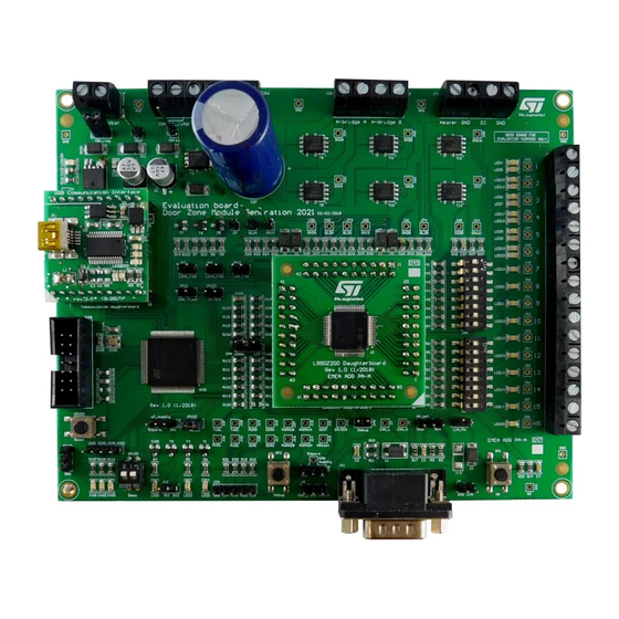
This document describes the STSW-L99DZ200 Graphical User Interface (GUI) dedicated to run the EVAL-L99DZ200.
The EVAL-L99DZ200 evaluation board is designed for automotive door zone application and it consists in a motherboard and
a daughter board on which the L99DZ200G device is assembled. Both the boards provide electronic control modules with
enhanced power management functionalities including a standby mode. These evaluation boards are designed to drive multiple
DC motors. The STSW-L99DZ200 has been developed by using C++ and it works with a motherboard based on SPC582B60
microcontroller programmed with dedicated firmware that drives the L99DZ200G assembled in the daughter board.
UM2888 - Rev 1 - June 2021
www.st.com
For further information contact your local STMicroelectronics sales office.
Advertisement
Table of Contents

Related Manuals for ST EVAL-L99DZ200


Summary of Contents for ST EVAL-L99DZ200
- Page 1 This document describes the STSW-L99DZ200 Graphical User Interface (GUI) dedicated to run the EVAL-L99DZ200. The EVAL-L99DZ200 evaluation board is designed for automotive door zone application and it consists in a motherboard and a daughter board on which the L99DZ200G device is assembled. Both the boards provide electronic control modules with enhanced power management functionalities including a standby mode.
-
Page 2: How To Connect The Eval-L99Dz200
UM2888 How to connect the EVAL-L99DZ200 How to connect the EVAL-L99DZ200 The following figure shows how to connect the EVAL-L99DZ200 and the main HW settings. Refer to the datasheet (see Section 11 Reference documents) for more information on the HW settings of the EVAL-L99DZ200. -
Page 3: Stsw-L99Dz200 Gui Installation
STSW-L99DZ200 GUI installation STSW-L99DZ200 GUI installation STSW-L99DZ200 GUI setup Install FDTI drive from supplier website Complete the connection (see the Figure 1. Eval-L99DZ200 connection), then power-on Run Setup_GUI.exe Figure 2. Graphic User Interface setup (1/2) When GUI installation is finished, GUI icon link is added on your desktop and a main window is showed: Figure 3. -
Page 4: Main Window Overview
Main window overview Main window overview When the EVAL-L99DZ200 is connected and the USB driver is installed, the message “Board connected and ready ….” will be displayed on the bottom left part of the main window. Here below an overview of the main functions of the main window is reported. -
Page 5: Figure 5. Main Window Menu Items
UM2888 Main window overview Figure 5. Main window menu items UM2888 - Rev 1 page 5/29... -
Page 6: Standard Control Panel
UM2888 Standard control panel Standard control panel Timers section Figure 6. Standard control window – timers section Figure 6. Standard control window – timers section the section of the GUI related to the configuration of the two timers embedded in L99DZ200G is shown. For each of the two timers, the period (from 0.01 s to 2 s) and the on time (from 0.1 ms to 20 ms) is programmable. -
Page 7: Supply Voltage Monitoring Section
UM2888 Supply voltage monitoring section Supply voltage monitoring section Figure 7. Standard control window – supply voltage monitoring section Figure 7. Standard control window – supply voltage monitoring section the section of the GUI related to the configuration of the supply voltage monitoring is shown. For both V and V there are some flags to enable the lockout and the OV/UV shutdown. -
Page 8: Can And Lin Transceivers Section
UM2888 CAN and LIN transceivers section CAN and LIN transceivers section Figure 8. Standard control window – CAN and LIN transceiver sections In the figure above the section of the GUI related to the setting of CAN and LIN transceivers is shown. •... -
Page 9: Watchdog Timing Section
UM2888 Watchdog timing section Watchdog timing section Figure 9. Standard control window – Watchdog timing sections In the figure above the section of the GUI related to the setting of WatchDog timing is reported. One of the following values can be here set, as defined by the WD_TIME_0/1 bits (CR2, bit 0 and bit 1): •... -
Page 10: Voltage Regulator Control Section
UM2888 Voltage regulator control section Voltage regulator control section Figure 10. Standard control window – voltage regulator 2 control section In the figure above the section of the GUI related to the control of the voltage regulator 2 is reported. The Off button allows to switch OFF or switch ON the V2;... -
Page 11: Wakeup Section
UM2888 Wakeup section Wakeup section Figure 11. Standard control window – wakeup section In the figure above the sections of the GUI related to the setting of wake-up are reported. One of the following values can be here set: • WU1 wakeup flag allows to wake up the L99DZ200G from WU1 pin;... -
Page 12: Error Flags Section
UM2888 Error flags section Error flags section Figure 12. Standard control window – error flags section In the figure above the sections of the GUI related to the errors and bus errors flags are reported. The following error flags are reported: •... -
Page 13: Power-On / Diagnosis Section
UM2888 Power-on / Diagnosis section Power-on / Diagnosis section Figure 13. Standard control window – power-on / diagnosis section In the figure above the section of the GUI related to the power-on / wakeup diagnosis is reported. One of the following values can be here observed: •... -
Page 14: Device Status And Global Status Byte Section
UM2888 Device status and global status byte section Device status and global status byte section Figure 14. Standard control window – device status and global status byte section In the figure above the sections of the GUI related to the device status information and global status byte are reported. -
Page 15: Mode Control Section
UM2888 Mode control section 4.10 Mode control section Figure 15. Standard control window – mode control section In the figure above the section of the GUI related to the mode control of the L99DZ200G is reported. 4.11 Reset section Figure 16. Standard control window –... - Page 16 UM2888 Reset section In the figure above the section of the GUI related to the reset of the L99DZ200G is reported. In this section one of the 4 possible reset thresholds (4.3 V, 4.0 V, 3.8 V and 3.5 V) can be configured. UM2888 - Rev 1 page 16/29...
-
Page 17: Outputs Control Panel
UM2888 Outputs control panel Outputs control panel Figure 17. STSW-L99DZ200 outputs control panel Figure 18. STSW-L99DZ200 outputs control - half-bridge outputs UM2888 - Rev 1 page 17/29... -
Page 18: Figure 19. Stsw-L99Dz200 Outputs Control - High Sides
UM2888 Outputs control panel Figure 19. STSW-L99DZ200 outputs control – high sides Figure 20. STSW-L99DZ200 outputs control – PWN configuration / automatic DC compensation UM2888 - Rev 1 page 18/29... -
Page 19: Electro Chrome Mirror Panel
UM2888 Electro-chrome mirror panel Electro chrome mirror panel Figure 21. STSW-L99DZ200 –electro-chrome mirror panel UM2888 - Rev 1 page 19/29... -
Page 20: Bridges Control Panel
UM2888 H-bridges control panel H-bridges control panel Figure 22. STSW-L99DZ200 – power H-bridge A control UM2888 - Rev 1 page 20/29... -
Page 21: Figure 23. Stsw-L99Dz200 - Power H-Bridge B Control
UM2888 H-bridges control panel Figure 23. STSW-L99DZ200 – power H-bridge B control Figure 24. STSW-L99DZ200 – power H-bridge A/B control UM2888 - Rev 1 page 21/29... -
Page 22: Spi Control Registers Panel
UM2888 SPI control registers panel SPI control registers panel Figure 25. STSW-L99DZ200 – SPI control register example UM2888 - Rev 1 page 22/29... -
Page 23: Spi Status Registers Panel
UM2888 SPI status registers panel SPI status registers panel Figure 26. STSW-L99DZ200 – SPI status register example UM2888 - Rev 1 page 23/29... -
Page 24: Watchdog/Por Settings Panel
UM2888 Watchdog/POR settings panel Watchdog/POR settings panel Figure 27. STSW-L99DZ200 – watchdog/POR settings UM2888 - Rev 1 page 24/29... -
Page 25: Reference Documents
UM2888 Reference documents Reference documents • L99DZ200G datasheet, DS13220. • EVAL-L99DZ200 Data brief, DB4431. UM2888 - Rev 1 page 25/29... -
Page 26: Revision History
UM2888 Revision history Table 1. Document revision history Date Version Changes 16-Jun-2021 Initial release. UM2888 - Rev 1 page 26/29... -
Page 27: Table Of Contents
How to connect the EVAL-L99DZ200 ........ -
Page 28: List Of Figures
Eval-L99DZ200 connection ........ - Page 29 ST’s terms and conditions of sale in place at the time of order acknowledgement. Purchasers are solely responsible for the choice, selection, and use of ST products and ST assumes no liability for application assistance or the design of Purchasers’...
Need help?
Do you have a question about the EVAL-L99DZ200 and is the answer not in the manual?
Questions and answers