Advertisement
Quick Links
UM2654
User manual
How to use the EVAL-L99MOD5xXP evaluation kit
Introduction
This document describes the STSW-L99MOD5xXP graphical user interface (GUI) dedicated to set and control the EVAL-
L99MOD5xXP family evaluation kit.
The EVAL-L99MOD5xXP evaluation kit consists in a motherboard and a daughterboard on which the L99MOD5xXP device is
assembled. Both of these evaluation boards provide electronic control modules with enhanced power management
functionalities including a standby mode. These evaluation boards are designed to drive multiple brushed DC motors and
additional loads in high-side configuration, such as bulbs, LEDs or protected supply.
The STSW-L99MOD5xXP has been developed using C++ and works with a motherboard based on an SPC560B microcontroller
which is programmed with a dedicated firmware to drive the specific L99MOD5xXP device assembled on the daughterboard.
UM2654 - Rev 1 - November 2019
www.st.com
For further information contact your local STMicroelectronics sales office.
Advertisement

Related Manuals for ST EVAL-L99MOD5xXP


Summary of Contents for ST EVAL-L99MOD5xXP
- Page 1 This document describes the STSW-L99MOD5xXP graphical user interface (GUI) dedicated to set and control the EVAL- L99MOD5xXP family evaluation kit. The EVAL-L99MOD5xXP evaluation kit consists in a motherboard and a daughterboard on which the L99MOD5xXP device is assembled. Both of these evaluation boards provide electronic control modules with enhanced power management functionalities including a standby mode.
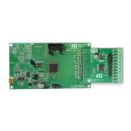
- Page 2 UM2654 Evaluation kit connection Evaluation kit connection The following figure shows how to connect the evaluation kit. Figure 1. Evaluation kit connection UM2654 - Rev 1 page 2/10...
- Page 3 UM2654 Evaluation kit installation Evaluation kit installation To install the evaluation kit, follow the instructions below: Install the VISA and Run-Time Engine drivers on the computer running the demo tool. Run the two downloaders below from the supplier's website to download and install the drivers: Install the FTDI driver from the supplier's website.
- Page 4 UM2654 Description of the graphical user interface Description of the graphical user interface The following figures present the main windows of the graphical user interface. Figure 2. Device selection Figure 3. Common commands Selection tabs VISA Port: please select the appropriate serial port Check sum mark: in case the checksum is correct, "OK"...
- Page 5 UM2654 Description of the graphical user interface Figure 4. Standard control tab OUT Control: half-bridge, high-side outputs control Enable device button Configuration registers settings Diagnostic Status: if any of these states occur, the corresponding status display will become red. Once the control register changes, the status register and all diagnostic information will be updated once.
- Page 6 UM2654 Description of the graphical user interface Figure 5. Current monitor and PWM tab Current value display window Current value Current detection select output Current monitor start button Clear window value button PWM configuration: on/off, frequency and duty cycle settings UM2654 - Rev 1 page 6/10...
- Page 7 UM2654 Description of the graphical user interface Figure 6. Control registers overview tab It is possible to write directly in the register by clicking on the desired bit, as shown in Figure 6. Control registers overview tab. Figure 7. Status registers overview tab UM2654 - Rev 1 page 7/10...
- Page 8 UM2654 Description of the graphical user interface Status Registers: SR0…SR2: it is possible to read and clear all status registers once or read them continuously. Once the control register changes, the status register and all diagnostic information will be updated once. Global Status Regster.
-
Page 9: Revision History
UM2654 Revision history Table 1. Document revision history Date Version Changes 20-Nov-2019 First release UM2654 - Rev 1 page 9/10... - Page 10 ST’s terms and conditions of sale in place at the time of order acknowledgement. Purchasers are solely responsible for the choice, selection, and use of ST products and ST assumes no liability for application assistance or the design of Purchasers’...
Need help?
Do you have a question about the EVAL-L99MOD5xXP and is the answer not in the manual?
Questions and answers