Table of Contents
Advertisement
Quick Links
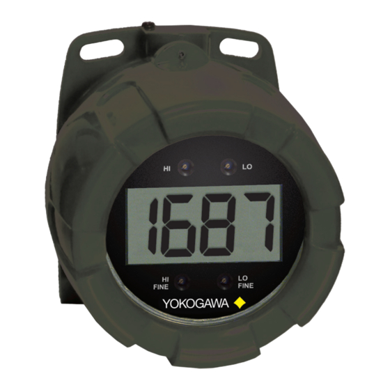
YPP6870 EXPLOSION-PROOF
LOOP-POWERED PROCESS METER
•
4-20 mA input
•
1 V drop (4 V with Backlight)
•
3½ Digits LCD, 1" High
•
Loop-Powered Backlight Option
•
®
HART
Protocol Transparent
•
Explosion-Proof, IP68, NEMA 4X Enclosure
•
Flanges for Wall or Pipe Mounting
•
Easy Calibration and Installation
•
Operates from -40 to 75°C
2 Dart Road • Newnan, Georgia 30265
770-253-7000 • 800-888-6400
Fax: 770-251-2088 • www.yokogawa-usa.com
Advertisement
Table of Contents

Related Manuals for YOKOGAWA YPP6870


Summary of Contents for YOKOGAWA YPP6870
- Page 1 Protocol Transparent • Explosion-Proof, IP68, NEMA 4X Enclosure • Flanges for Wall or Pipe Mounting • Easy Calibration and Installation • Operates from -40 to 75°C 2 Dart Road • Newnan, Georgia 30265 770-253-7000 • 800-888-6400 Fax: 770-251-2088 • www.yokogawa-usa.com...
- Page 2 Yokogawa Corporation of America warrants this product against defects in material or workmanship for the specified period under “Specifications” from the date of shipment from the factory. Yokogawa’s liability under this limited warranty shall not exceed the purchase value, repair, or replacement of the defective unit.
-
Page 3: Introduction
Instruction Manual INTRODUCTION The YPP6870 is a rugged, loop-powered meter with 1" display digits in an explosion- proof enclosure for demanding applications in hazardous areas or in the harshest environmental conditions. The meter derives all of its power from the 4-20 mA loop with a small 1 volt drop for easy installation in almost any system. -
Page 4: Table Of Contents
Figure 1. YPP6870 Connectors ............... 11 Figure 2. YPP6870 Input Connections without Backlight ..... 12 Figure 3. YPP6870 Input Connections with Loop-Powered Backlight . 12 Figure 4. Enclosure Dimensions – Front View ........17 Figure 5. Enclosure Dimensions – Side Cross Section View ....18... -
Page 5: Specifications
YPP6870 Loop-Powered Process Meter Instruction Manual SPECIFICATIONS Except where noted all specifications apply to operation at +25°C. General DISPLAY 3 ½ digit LCD 1" (25.4 mm); -1999 to 1999 DISPLAY 2.5 Updates/Second UPDATE RATE OVERRANGE Display reads on the left most digit... -
Page 6: Input
YPP6870 Loop-Powered Process Meter Instruction Manual Input ACCURACY ±0.1% of full span ±1 count TEMPERATURE 150 PPM/°C from -40 to 75°C ambient DRIFT DECIMAL POINT User selectable decimal point CALIBRATION 4 mA input: -1000 to +1000; 20 mA between 20 and 2000 RANGE counts greater than 4 mA display. -
Page 7: Product Ratings And Approvals
This information is contained within the serial number with the first four digits representing the year and month in the YYMM format. For European Community: The YPP6870 must be installed in accordance with the ATEX directive 94/9/EC, and the product certificate Sira 13ATEX1121X. -
Page 8: Electromagnetic Compatibility
YPP6870 Loop-Powered Process Meter Instruction Manual Electromagnetic Compatibility EN 61326:2006 EMISSIONS Safety requirements for measurement, control, and laboratory use – Industrial Group 1 Class A ISM emissions requirements Class A Radiated Emissions EN 61326:2006 IMMUNITY Safety requirements for measurement, control, and laboratory use ±4 kV contact,... -
Page 9: Installation
YPP6870 Loop-Powered Process Meter Instruction Manual INSTALLATION For Installation in USA: The YPP6870 must be installed in accordance with the National Electrical Code (NEC) NFPA 70. For Installation in Canada: Install in accordance with applicable local and national regulations (e.g. NEC). The YPP6870 must be installed in accordance with the Canadian Electrical Code CSA 22.1. -
Page 10: Unpacking
Mounting The YPP6870 has two slotted mounting flanges that may be used for pipe mounting or wall mounting. Alternatively, the unit may be supported by the conduit using the conduit holes provided. -
Page 11: Connections
YPP6870 Loop-Powered Process Meter Instruction Manual Connections WARNINGS • Static electricity can damage sensitive components. • Observe safe handling precautions for static-sensitive components. • Use proper grounding procedures/codes. • If the meter is installed in a high voltage environment and a fault or installation error occurs, high voltage may be present on any lead or terminal. -
Page 12: Connections & Wiring Diagrams
4 V. The backlight option is recommended for dim lighting conditions and is enabled when wired as shown in Figure 3. Figure 2. YPP6870 Input Connections without Backlight Figure 3. YPP6870 Input Connections with Loop-Powered Backlight... -
Page 13: Setup
YPP6870 Loop-Powered Process Meter Instruction Manual SETUP Overview Setup is done using four rotary control dials located on the front of the display module that are accessed when the meter cover is removed. Setup is performed using a 4-20 mA signal source and scaling the 4 and 20 mA readings using the control dials. -
Page 14: Setting Up The Meter
YPP6870 Loop-Powered Process Meter Instruction Manual Setting Up the Meter Calibrating the Meter The meter is provided factory calibrated to display -50.0 at 4 mA and 150.0 at 20 mA. HI and LO coarse and fine controls are labeled on the front of the display. Use the HI and LO controls for large range changes during calibration and the HI FINE and LO FINE controls for precision changes. -
Page 15: Factory Defaults & User Settings
YPP6870 Loop-Powered Process Meter Instruction Manual Factory Defaults & User Settings The following table shows the factory setting for most of the programmable parameters on the meter. Next to the factory setting, the user may record the new setting for the particular application. -
Page 16: Troubleshooting
YPP6870 Loop-Powered Process Meter Instruction Manual TROUBLESHOOTING The rugged design and the user-friendly interface of the meter should make it unusual for the installer or operator to refer to this section of the manual. If the meter is not working as expected, refer to the recommendations below. -
Page 17: Mounting Dimensions
YPP6870 Loop-Powered Process Meter Instruction Manual MOUNTING DIMENSIONS All units: inches [mm] 3.35 [85.1] 2.25 [57.1] 0.32 [8.2] 5.65 [143.5] 5.25 [133.4] Figure 4. Enclosure Dimensions – Front View... -
Page 18: Figure 5. Enclosure Dimensions - Side Cross Section View
YPP6870 Loop-Powered Process Meter Instruction Manual 3.35 [85.0] 4.15 [105.5] 4.86 [123.5] 3.22 [81.9] Figure 5. Enclosure Dimensions – Side Cross Section View Note: The supplied conduit plug may extend up to 0.6 in [15 mm] from the conduit opening when installed. -
Page 19: Ec Declaration Of Conformity
YPP6870 Loop-Powered Process Meter Instruction Manual EC DECLARATION OF CONFORMITY Issued in accordance with ATEX Directive 94/9/EC Manufacturer: Yokogawa Corporation of America 2 Dart Road Newnan, Georgia 30265 USA Device: YPP6870 Series Process Meter Notified Body: Sira Certification Service, notified body no. 0518... - Page 20 YPP6870 Loop-Powered Process Meter Instruction Manual LIM6870YK_B 10/13...
Need help?
Do you have a question about the YPP6870 and is the answer not in the manual?
Questions and answers