
Related Manuals for YOKOGAWA 2 Series


Summary of Contents for YOKOGAWA 2 Series
- Page 1 Plus Y800 Universal Digital Meter Series 2 INSTRUCTION MANUAL Now with Ethernet 2 Dart Rd, Newnan, GA 30265, USA Phone: 770-251-8700, Fax: 770-251-2088 http://www.yca.com - 69 -...
-
Page 2: Ordering Guide
1. ORDERING GUIDE Configure a model number in this format: Y820201DCV1, CBL01 Y8 . .Digital panel meter with DC Amperes Strain Gauge, Potentiometer screw terminal connectors. (4-wire ratio) DCA1 ....2.0000 mA DCA2 ....20.000 mA SG ..0-200 mV = 0-100.00 Display Color DCA3 .... -
Page 3: Table Of Contents
2. TABLE OF CONTENTS ORDERING GUIDE ..................... 2 TABLE OF CONTENTS ....................3 PRODUCT INTRODUCTION ..................4 RECEIVING & UNPACKING ..................5 SAFETY CONSIDERATIONS ..................5 CONNECTOR WIRING INFORMATION ..............6 MECHANICAL ASSEMBLY ..................8 FRONT PANEL SETUP KEYS ..................10 ENABLING &... -
Page 4: Product Introduction
3. PRODUCT INTRODUCTION Our digital panel meters are versatile, cost effective solutions to a wide variety of monitoring and control applications. Depending on the choice of signal conditioner, they are easily set up for an accurate display of temperature, pressure, flow, weight, voltage or current, all in appropriate engineering units and with zero and span adjustment when needed. -
Page 5: Receiving & Unpacking
4. RECEIVING & UNPACKING Your meter was carefully tested and inspected prior to shipment. Should the meter be damaged in shipment, notify the freight carrier immediately. In the event the meter is not configured as ordered or the unit is inoperable, return it to the place of purchase for repair or replacement. -
Page 6: Connector Wiring Information
6. CONNECTOR WIRING INFORMATION CONNECTORS Connectors for signal and power are UL-rated screw-clamp terminal blocks that plug into mating jacks on the printed circuit board. Communication connectors are a single RJ11 plug for RS232, dual RJ11 plugs for RS485, dual RJ45 plugs for RS485 Modbus, or USB. Note: Control inputs 1 &... - Page 7 P3 - SERIAL COMMUNICATIONS P4 - ANALOG OUTPUT RS232 INTERFACE Computer ISO GND RS485 INTERFACE - FULL DUPLEX RS485 INTERFACE - HALF DUPLEX ISO GND ISO GND ATX / ARX ATX / ARX BTX / BRX BTX / BRX ISO GND ISO GND RS485-MODBUS - FULL DUPLEX RS485-MODBUS - HALF DUPLEX...
-
Page 8: Mechanical Assembly
7. MECHANICAL ASSEMBLY REMOVING THE REAR PANEL First remove any connectors. Use one hand to press in the two sides of the rear of the case, and the other hand to press down the two protruding tab releases at the top of the rear panel (see figure below). - Page 9 Note: Corresponding main board and option board connectors have the same number of electrical lines. When an option board is correctly installed, the top and bottom edges of the main board and option board are aligned. REASSEMBLING YOUR METER Slide the electronics assembly into the case until the display board is seated flush against the front overlay.
-
Page 10: Front Panel Setup Keys
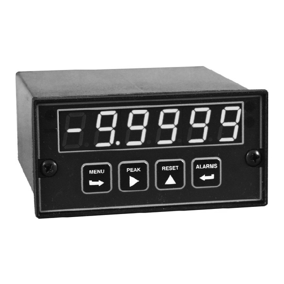
8. FRONT PANEL SETUP KEYS Meter Front Panel There are four front panel keys, which change function for the Run Mode and Menu Mode, effectively becoming eight keys. The keys are labeled with alphanumeric captions (MENU, PEAK, RESET, ALARMS) for the Run Mode and with symbols ( right arrow, right triangle, up triangle,... - Page 11 KEYS IN MENU MODE Right Arrow Key (MENU). Pressing steps the meter through all menu items that have been enabled and then back to the Run Mode. With the DC signal conditioner board and no option boards, available menu items are _InPut, SEtuP, ConFG, _FiLtr, dEc.Pt, SCALE, OFFst, 3.
-
Page 12: Enabling & Locking Out Menu Items
9. ENABLING & LOCKING OUT MENU ITEMS For security reasons and ease of meter operation, any and all menu items may be disabled or "locked out" so that they are no longer directly accessible from the front panel. Each function to be disabled is set to "1"... -
Page 13: Reading Coordinates Of 2 Points Scaling Method
10. READING COORDINATES OF 2 POINTS SCALING METHOD When the reading coordinates of 2 points scaling method has been selected under SEtuP, the four menu items below will appear ahead of all other menu items when the MENU or key is first pressed from the run mode. This scaling method applies a straight line fit between two points, which are determined from actual transducer signals and the desired corresponding meter readings. -
Page 14: Dc Volts, Amps, Process, Strain Input
11. DC VOLTS, AMPS, PROCESS, STRAIN INPUT The DC Volts, Amps, Process and Strain meters utilize the DC signal conditioner board, which needs to be configured via jumpers for the desired voltage or current range. All signal ranges are factory calibrated with calibration factors stored in EEPROM. The meter software recognizes the board and will bring up the appropriate menu items for it;... - Page 15 Board Revisions Q and R Voltage Ranges Jumpers FS Input ±200.00 mV ±2.0000 V ±20.000 V ±200.00 V ±300V (UL) ±600V (not UL) Current Ranges Jumpers FS Input ±2.0000 mA e, g ±20.000 mA d, g ±200.00 mA c, g ±5.000 A a, b, g 1.
- Page 16 KEYSTROKES FOR SETUP If the MENU key does not work, see Section 9 “Enabling & Locking Out Menu Items.” Press Menu Press Digit Press Value Select Select Key Select Key _InPut _dC U __0.2U __2.0U _20.0U 200.0U 600.0U Selection of signal DC Volts 0.2, 2, 20, 200, 660V FS input type &...
- Page 17 Press Menu Press Digit Press Value Select Select Key Select Key ConFG 000_0 Not rate of change Meter Configuration Operation as a rate of Rate x 0.1 Rate x 1 change meter. Rate x 10 Rate x 100 Extended meter only. Rate x 1000 Rate x 10000 000_0...
- Page 18 Press Menu Press Digit Press Value Select Select Key Select Key Scaling method “Scale and Offset” if selected under SEtuP SCALE 0.0000 0.0000 0.0000 Select thru for flashing first digit, thru Scale factor for other flashing digits. Select decimal point 0.0000 0.0000 0.0000 location when decimal point is flashing.
- Page 19 Option board dependent menu items ALSEt. ALS34 dEU1H dEU2H dEU1b dEU2b dEU3H DEU4H DEU3b DEU4b Menu items related to alarm setup These will only appear if a relay board is detected. If so, please see Section16. AnSEt. Hi.. Menu items related to analog output setup. These will only appear if an analog output board is detected.
-
Page 20: Load Cell & Microvolt Input
12. LOAD CELL & MICROVOLT INPUT The Load Cell and Microvolt meters utilize the load cell signal conditioner board, which offers sensitivity to ±20 mV full scale and 4 or 6-wire load cell connection. This board needs to be configured via jumpers for the desired voltage range. All signal ranges are factory calibrated with calibration factors stored in EEPROM. - Page 21 KEYSTROKES FOR SETUP If the MENU key does not work, see Section 9 “Enabling & Locking Out Menu Items.” Press Menu Press Digit Press Value Select Select Key Select Key _InPut _Strn _20.0____50.0_ _100.0 _250.0 _500.0 Selection of signal Strain or ratiometric 20, 50, 100, 250, 500 mV FS voltage input type &...
- Page 22 Press Menu Press Digit Press Value Select Select Key Select Key ConFG 000_0 Not rate of change Meter Configuration Operation as a rate of Rate x 0.1 change meter. Rate x 1 Extended meter only. Rate x 10 Rate x 100 Rate x 1000 Rate x 10000 000_0...
- Page 23 Press Menu Press Digit Press Value Select Select Key Select Key Scaling method “Scale and Offset” if selected under SEtuP SCALE 0.0000 0.0000 0.0000 Select thru for flashing first digit, thru Scale factor for other flashing digits. Select decimal point 0.0000 0.0000 0.0000 location when decimal point is flashing.
- Page 24 Option board dependent menu items ALSEt. ALS34 dEU1H dEU2H dEU1b dEU2b dEU3H DEU4H DEU3b DEU4b Menu items related to alarm setup These will only appear if a relay board is detected. If so, please see Section16. AnSEt. Hi.. Menu items related to analog output setup. These will only appear if an analog output board is detected.
-
Page 25: Ac Rms Volts & Amps Input
13. AC TRUE RMS VOLTS & AMPS INPUT AC voltage or current measurement utilizes the True RMS signal conditioner board which uses precision circuitry to compute the root-mean-square of complex waveforms from 10 Hz to 10 kHz. Accurate measure- ments are obtained with spikes up to 3 times the maximum of each range. - Page 26 can be set for direct readout in (milli)volts or (milli)amperes. Decimal point selection does not affect the counts. For example, a 20V input may be displayed as 20.000V or 20000 mV. The 5A range, designed for use with a 5A current transformer (CT), is scaled to produce 5000 counts with a scale factor of 1 and an offset of 0.
- Page 27 KEYSTROKES FOR SETUP If the MENU key does not work, see Section 9 “Enabling & Locking Out Menu Items.” Press Menu Press Digit Press Value Select Select Key Select Key _InPut _AC U __0.2U __2.0U _20.0U 200.0U 600.0U Selection of signal AC Volts 0.2, 2, 20, 200, 660V FS input type &...
- Page 28 Press Menu Press Digit Press Value Select Select Key Select Key ConFG 000_0 Not rate of change Meter Configuration Operation as a rate of Rate x 0.1 change meter. Rate x 1 Extended meter only. Rate x 10 Rate x 100 Rate x 1000 Rate x 10000 00 _ _0...
- Page 29 Press Menu Press Digit Press Value Select Select Key Select Key Scaling method “Scale and Offset” if selected under SEtuP SCALE 0.0000 0.0000 0.0000 Select thru for flashing first digit, thru Scale factor for other flashing digits. Select decimal point 0.0000 0.0000 0.0000 location when decimal point is flashing.
- Page 30 Option board dependent menu items ALSEt. ALS34 dEU1H dEU2H dEU1b dEU2b dEU3H DEU4H DEU3b DEU4b Menu items related to alarm setup These will only appear if a relay board is detected. If so, please see Section16. AnSEt. Hi.. Menu items related to analog output setup. These will only appear if an analog output board is detected.
-
Page 31: Thermocouple Input
14. THERMOCOUPLE INPUT The thermocouple signal conditioner board used for temperature measurement can be confi- gured via jumpers for 7 thermocouple types, each in a single range: J, K, T, E, N, S, R. The meter software recognizes the board and will bring up the appropriate menu items for it; however, it does not recognize the jumper settings. - Page 32 KEYSTROKES FOR SETUP If the MENU key does not work, see Section 9 “Enabling & Locking Out Menu Items.” Press Menu Press Digit Press Value Select Select Key Select Key _InPut __tC_ Type J, °F or °C --.J °F_ °C_ Selection of signal Thermocouple ...K...
- Page 33 Press Menu Press Digit Press Value Select Select Key Select Key ConFG 0 00_0 No used. Meter Configuration 0 0 _ _0 Peak Display. Also selects “Peak” in Operation of front “Peak or Valley” at rear connector. panel PEAK button Valley Display.
-
Page 34: Rtd & Resistance Input
15. RTD & RESISTANCE INPUT The standard RTD and resistance signal conditioner board can be configured via jumpers for four RTD types (DIN 100 platinum, ANSI 100 platinum, 120 nickel, 10 copper) or five resistance ranges (from 20.000 to 200.00 k ). A fixed 2 M resistance range (R6 ordering option) is provided by a factory modified signal conditioner board with component changes. - Page 35 RTD & RESISTANCE CONNECTION With the appropriate jumper settings, RTD and resistance measurements allow 2, 3 or 4- wire RTD hookup to the J5 connector, as illustrated. The meter applies a fixed excita- tion current. In 4-wire hookup, lead resistance is not a factor, since different pairs of wires are used for excitation and sensing.
- Page 36 KEYSTROKES FOR SETUP If the MENU key does not work, see Section 9 “Enabling & Locking Out Menu Items.” Press Menu Press Digit Press Value Select Select Key Select Key _InPut _-rtd_ °F- Pt100 RTD, DIN alpha .00385, °F Selection of signal °C.
- Page 37 Press Menu Press Digit Press Value Select Select Key Select Key SEtuP 00_0 0 1 = Function Reset 2 = Display Blank Meter Setup Control inputs 1 & 2 1 = Hold 2 = Display Blank (continued) 1 = Peak or Valley 2 = Display Blank (continued) 1 = Tare 2 = Display Blank...
- Page 38 Press Menu Press Digit Press Value Select Select Key Select Key FiLtr 0000 0 Autofilter Filtering Input signal filtering. Batch average, 16 readings (continued) Can be applied to dis- Moving average, 0.08 sec. play, setpoint, analog Moving average, 0.15 sec. output, data output.
-
Page 39: Dual & Quad Relay Output Options
16. DUAL OR QUAD RELAY OUTPUT OPTION An optional relay board may be installed in the meter main board at plug position P2, adjacent to the power supply board. Four board versions are available: 2 or 4 relays, mechanical or solid state. Once installed, the relay board is recognized by the meter software or PC-based Instrument Setup software, which will bring up the appropriate menu... - Page 40 KEYSTROKES FOR SETPOINT SETUP If the MENU key does not work, see Section 9 “Enabling & Locking Out Menu Items.” Press Menu Press Digit Press Value Select Select Key Select Key ALSEt 0 0000 Relay 1 active on Relay 2 active on Alarm Setup for Relay alarm state Relay 1 active off...
- Page 41 Press Menu Press Digit Press Value Select Select Key Select Key ALS34 00 0 00 AL3 active high AL4 active high Alarm Setup for Alarm operates at and AL3 active low AL4 active high relays 3 & 4 above setpoint (active AL3 disabled AL4 active high (continued)
-
Page 42: Analog Output Option
17. ANALOG OUTPUT OPTION An optional analog board may be installed in the meter at rear panel jack position J4, adjacent to the signal conditioner board. Once installed, this board is recognized by the meter, which will bring up the appropriate menu items for it. These will not be brought up if an analog output board is not installed. -
Page 43: Serial Communication Options
18. SERIAL COMMUNICATION OPTIONS A serial communications board may be connected to the meter main board at plug position P13 (middle position). Available boards are RS232, RS485 (with dual RJ11 connectors), RS485 Modbus (with dual RJ45 connectors), USB, USB-to-RS485 converter, Ethernet, and Ethernet-to-RS485 converter. - Page 44 Basic Ethernet Board No jumpers needed. RS232 Board e - Normal operation. f - Slave display to RS232 from another meter. g - Pull-up resistor on RTS line. Note: Board is shipped with jumpers e and g installed RS485 Board, Full Duplex Operation b &...
- Page 45 SERIAL CONNECTION EXAMPLES...
- Page 46 KEYSTROKES FOR SETUP If the MENU key does not work, see Section 9 “Enabling & Locking Out Menu Items.” Press Menu Press Digit Select Press Value Select Select Key .SEr __ 0 00 Send unfiltered signal Fixed Parameters: Output filtering Send filtered signal No parity __0 0 0 U...
- Page 47 Press Menu Press Digit Select Press Value Select Select Key .SEr _ 0 000 U No line feed after carriage return Serial Setup 2 Line feed Line feed after carriage return _0 0 00 U No alarm data Alarm data with readings Alarm data with reading _00 0 0 U Continuous data output...
-
Page 48: Excitation Output & Power Supply
19. EXCITATION OUTPUT & POWER SUPPLY Three isolated transducer excitation output levels are available from the power supply board. These are selectable via jumpers b, c, d, e, f in the upper right of the board, as illustrated. In addition, the board provides three jumper positions for special features. The same jumper locations apply to the universal power supply (85-264 Vac) and to the low voltage power supply (12-32 Vac or 10-48 Vdc). -
Page 49: Instrument Setup Via Pc
20. INSTRUMENT SETUP VIA PC Instrument Setup software is a PC program which is much easier to learn than front panel programming. It is of benefit whether or not the meter is connected to a PC. With the meter connected to a PC, it allows uploading, editing and downloading of setup data, execution of commands under computer control, listing, plotting and graphing of data, and computer prompted calibration. - Page 50 SETUP OF CONNECTED METER A setup file can be retrieved from the meter (DPM => Get Setup), be edited (View => Setup), be saved to disk (File => Save Setup), be retrieved from disk (File => Open Setup), and be downloaded into one or multiple meters (DPM => Put Setup). Downloading of setup files from a PC can be a major time saving when multiple meters have to be set up in the same way.
- Page 51 • The Readings pull-down menu provides three formats to display DPM data on the PC monitor. Use the Pause and Continue buttons to control the timing of data collection, then press Print for a hardcopy using your PC printer. - List presents the latest readings in a 20-row by 10-column table. Press Pause at any time to freeze the display.
-
Page 52: Custom Curve Linearization
21. CUSTOM CURVE LINEARIZATION Curve.exe is a DOS-based, executable PC program used to set up an Extended meter so that the readings have a user-defined, non-linear relationship with the input signal. The calculated linearizing parameters are downloaded into non-volatile memory of the meter. For example, it allows a meter to correct for transducer nonlinearity or to display volume of an irregularly shaped tank based on liquid level. - Page 53 4) Equation entry mode, where the coefficients of a polynomial Y = K1X^P1 + K2X^P2 + K3*X^P3 + are entered. Up to 20 terms are allowed. An offset can be built into X. You will be asked if your DPM has a revision of DPM4L or later. You will normally select 2 (yes), since revision DPM4L started to ship in August 2000.
-
Page 54: Meter Calibration
22. METER CALIBRATION All analog input and analog output ranges of the meter have been digitally calibrated at the factory prior to shipment using calibration equipment certified to NIST standards. Calibration constants are stored digitally in non-volatile memory in EEPROM on the signal conditioner board and analog output board. -
Page 55: Specifications
23. SPECIFICATIONS Meter Display Type ........5 LED, 7-segment, 14.2mm (.56") high digits & 3 LED indicators Color ........................Red or green Range ..............-99999 to +99999 and -99990 to +99990 A to D Conversion Technique (Pat.5,262,780) ................ Concurrent Slope Read Rate ............... - Page 56 Thermocouple (0.1°, 1° resolution) DC Volts Range Resol. Resist. Error Type Range Error 200.00 mV 10 V -210 to 760°C .01% FS ±0.09°C 0.01% 2.0000 V 100 V -347to 1400°F .01% FS ±0.16°F of FS 20.000 V 1 mV 10 M ±2 cts -244 to 1372°C .01% FS ±0.10°C...
- Page 57 Load Cell Input Range Resolution Resistance Zero Range Span Range Error 20.000 mV 50.000 mV 2.5 V -99999 to 0.01% of FS 100.00 mV 0 to ±99,999 99999 ±2 cts 250.00 mV 12.5 V 500.00 mV 25 V Thermocouple Accuracy Span Tempco ..................
- Page 58 Response Time ..................50/60Hz update rate Scaling of Reading for Zero Output ............-99,999 to +99,999 Scaling of Reading for Full Scale Output ........... -99,999 to +99,999 Isolation rating between signal common and analog output ........250V ac Insulation dielectric strength between signal common and analog output ........................
-
Page 59: Glossary Of Terms
24. GLOSSARY OF TERMS Adaptive Filter Threshold A threshold which causes an adaptive moving average filter to be reset to the latest reading when the accumulated difference between individual readings and the filtered reading exceeds that threshold. Adaptive moving average filtering allows a meter to respond rapidly to actual changes in signal while filtering out normal noise. - Page 60 deviation band, and de-actuates when the reading falls outside. A limit (e.g., 50 counts) is set up around both sides of the setpoint to create a deviation band (e.g., 100 counts). Setting up a passband around a setpoint is often used for component testing.
- Page 61 Hysteresis, Span Same relay operation as for split hysteresis, but specified differently. Here the setpoint is the upper control limit, and the lower control limit is the setpoint less the hysteresis band. The meter programming mode used for input Menu Mode and range selection, meter setup, and meter configuration.
- Page 62 The value displayed by the meter. “Taking a reading” is the action of the meter Reading to make an analog-to-digital conversion. Readings are taken at 60/sec with 60 Hz power or 50/sec with 50 Hz power, and are displayed with an update rate of 3.5/sec with 60 Hz power or 3.0/sec with 50 Hz power.
- Page 63 Scaling, Scale and Offset Method A scaling method where scale and offset are entered manually. Scaling, Reading Coordinates of 2 Points Method A scaling method, where the low and high input values are determined from actual signals. A known low signal is first applied to the meter. That signal is captured as the low input value, and the desired low reading is entered.
-
Page 64: Warranty
In the event of a defect during the warranty period, the unit should be returned, freight prepaid (and all duties and taxes) by the Buyer, to the authorized Yokogawa distributor where the unit was purchased. The distributor, at its option, will repair or replace the defective unit. The unit will be returned to the buyer with freight charges prepaid by the distributor.
Need help?
Do you have a question about the 2 Series and is the answer not in the manual?
Questions and answers