Moxa Technologies AirWorks AWK-3131A-M12-RCC Quick Installation Manual
Hide thumbs
Also See for AirWorks AWK-3131A-M12-RCC:
- User manual (94 pages) ,
- Quick installation manual (19 pages)
Table of Contents
Advertisement
Quick Links
Download this manual
See also:
User Manual
AWK-3131A-M12-RCC
Quick Installation Guide
Moxa Americas:
Toll-free: 1-888-669-2872
Tel:
1-714-528-6777
Fax:
1-714-528-6778
Moxa Europe:
Tel:
+49-89-3 70 03 99-0
Fax:
+49-89-3 70 03 99-99
Moxa India:
Tel:
+91-80-4172-9088
Fax:
+91-80-4132-1045
Moxa AirWorks
Edition 2.0, January 2019
Technical Support Contact Information
www.moxa.com/support
2019 Moxa Inc. All rights reserved.
Moxa China (Shanghai office):
Toll-free: 800-820-5036
Tel:
+86-21-5258-9955
Fax:
+86-21-5258-5505
Moxa Asia-Pacific:
Tel:
+886-2-8919-1230
Fax:
+886-2-8919-1231
P/N: 1802031312031
*1802031312031*
Advertisement
Table of Contents

Related Manuals for Moxa Technologies AirWorks AWK-3131A-M12-RCC


Summary of Contents for Moxa Technologies AirWorks AWK-3131A-M12-RCC
-
Page 1: Quick Installation Guide
AWK-3131A-M12-RCC Quick Installation Guide Moxa AirWorks Edition 2.0, January 2019 Technical Support Contact Information www.moxa.com/support Moxa Americas: Moxa China (Shanghai office): Toll-free: 1-888-669-2872 Toll-free: 800-820-5036 Tel: 1-714-528-6777 Tel: +86-21-5258-9955 Fax: 1-714-528-6778 Fax: +86-21-5258-5505 Moxa Europe: Moxa Asia-Pacific: Tel: +49-89-3 70 03 99-0 Tel: +886-2-8919-1230 Fax:... -
Page 2: Package Checklist
Overview Moxa’s new AWK-3131A-M12-RCC is a 3-in-1 industrial AP/client device designed specifically for rail carriage-to-carriage communication and can provide up to 300 Mbps speed with IEEE 802.11n technology. The AWK-3131A-M12-RCC combines two adjacent 20 MHz channels into a single 40 MHz channel to deliver a potent combination of greater reliability and more bandwidth. - Page 3 Step 3: Set up the computer’s IP address Set an IP address on the same subnet as the AWK-3131A-M12-RCC. Since the AWK-3131A-M12-RCC’s default IP address is 192.168.127.253, and the subnet mask is 255.255.255.0, you should set the IP address of the computer to 192.168.127.xxx and subnet mask to 255.255.255.0.
-
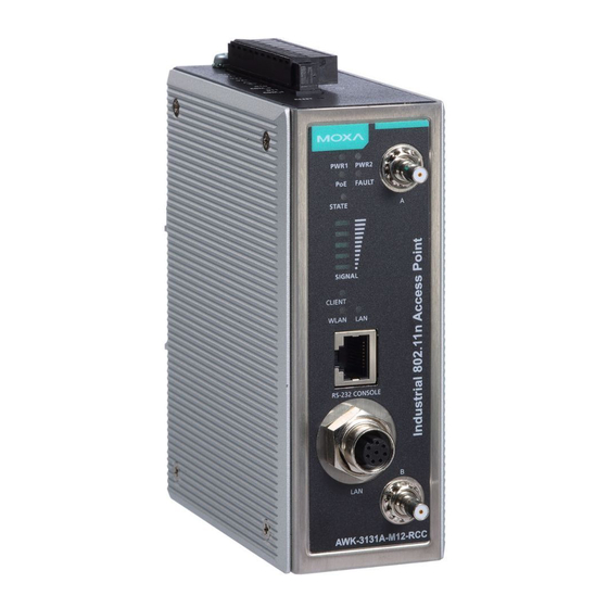
Page 4: Panel Layout Of The Awk-3131A-M12-Rcc
Panel Layout of the AWK-3131A-M12-RCC 1. Grounding screw (M5) 2. Terminal block for PWR1, PWR2, relay, DI0, and DI1 3. Reset button 4. A antenna connector 5. B antenna connector 6. System LEDs: PWR1, PWR2, PoE, FAULT, and STATE 7. Signal strength indicator 8. -
Page 5: Mounting Dimensions (Unit = Mm)
Mounting Dimensions (unit = mm) DIN-rail Mounting The aluminum DIN-rail attachment plate should be fixed to the back panel of the AWK-3131A-M12-RCC when you take it out of the box. If you need to reattach the DIN-rail attachment plate to the AWK-3131A-M12-RCC, make sure the stiff metal spring is situated towards the top, as shown in the figures below. -
Page 6: Wall Mounting (Optional)
Wall Mounting (optional) For transportation applications that require an EN 50155 certification report, we strongly recommend the purchase of the optional AWK-3131A-M12-RCC wall-mounting kit, which has passed EN 50155 testing. This wall-mounting kit is also convenient for other applications that require mounting the AWK-3131A-M12-RCC to a wall. STEP 1: Remove the aluminum DIN-rail attachment plate... -
Page 7: Wiring Requirements
WARNING • This equipment is intended to be used in a Restricted Access Location, such as a dedicated computer room, a cabinet, or space specially reserved for device installation onboard a train. Access can only be gained by SERVICE PERSONS or by USERS who have been instructed to comply with the safety rules thereby avoiding casualties from electric shock, cutting from a sharp edge, heat from a metallic surface, and so on. -
Page 8: Grounding The Moxa Awk-3131A-M12-Rcc
ATTENTION This product is intended to be supplied by a Listed Power Unit marked “Class 2” or “LPS” and rated O/P: 12 to 48 VDC, minimum 6 W (12 V to 48V), 25°C. ATTENTION Make sure the external power adapter (includes power cords and plug assemblies) provided with the unit is certified and suitable for use in your country. -
Page 9: Wiring The Dual Power Inputs
Wiring the Dual Power Inputs The top two pairs of contacts of the 10-contact terminal block connector on the AWK-3131A-M12-RCC’s top panel are used for the AWK-3131A-M12-RCC’s two DC inputs. Top and front views of the terminal block connector are shown below. STEP 1: Insert the negative/positive DC wires into the V-/V+ terminals. -
Page 10: Communication Connections
STEP 1: Screw the cable holder onto the bottom of the AWK-3131A-M12-RCC. STEP 2: After mounting the AWK-3131A-M12-RCC and plugging in the LAN cable, tighten the cable along the device and wall. Communication Connections 10/100/1000BaseT(X) Ethernet Port Connection All AWK-3131A-M12-RCCs have a 10/100/1000BaseT(X) Ethernet port (8-pin shielded M12 connector with A coding). -
Page 11: Reset Button
RS-232 Connection The AWK-3131A-M12-RCC has one RS-232 (8-pin RJ45) console port on the front panel. Use either an RJ45-to-DB9 or RJ45-to-DB25 cable to connect the AWK-3131A-M12-RCC console port to your PC’s COM port. You may then use a console terminal program to access the AWK-3131A-M12-RCC for console configuration. -
Page 12: Specifications
Color State Description Power is being supplied via PoE. Amber Power is not being supplied via PoE. System is booting or A system configuration error exists or A relay event has occurred Blinking Cannot get an IP address from the (slowly at DHCP server FAULT... - Page 13 Spread Spectrum • DSSS with DBPSK, DQPSK, CCK and Modulation • OFDM with BPSK, QPSK, 16QAM, 64QAM (typical) • 802.11b: CCK @ 11/5.5 Mbps, DQPSK @ 2 Mbps, DBPSK @ 11 Mbps • 802.11a/g: 64QAM @ 54/48 Mbps, 16QAM @ 36/24 Mbps, QPSK @ 18/12 Mbps, BPSK @ 9/6 Mbps •...
- Page 14 • Typ. 20±1.5dBm @ MCS4 20 MHz • Typ. 19±1.5dBm @ MCS5 20 MHz • Typ. 18±1.5dBm @ MCS6 20 MHz • Typ. 18±1.5dBm @ MCS7 20 MHz • Typ. 23±1.5dBm @ MCS8 20 MHz • Typ. 21±1.5dBm @ MCS9 20 MHz •...
- Page 15 •Typ. 18±1.5dBm @ MCS6 40 MHz •Typ. 18±1.5dBm @ MCS7 40 MHz •Typ. 23±1.5dBm @ MCS8 40 MHz •Typ. 20±1.5dBm @ MCS9 40 MHz •Typ. 20±1.5dBm @ MCS10 40 MHz •Typ. 20±1.5dBm @ MCS11 40 MHz •Typ. 19±1.5dBm @ MCS12 40 MHz •Typ.
-
Page 16: Protocol Support
• -69 dBm @ MCS14 40 MHz • -67 dBm @ MCS15 40 MHz 802.11a: • -90 dBm @ 6 Mbps • -88 dBm @ 9 Mbps • -88 dBm @ 12 Mbps • -85 dBm @ 18 Mbps • -81 dBm @ 24 Mbps •... -
Page 17: Physical Characteristics
LED Indicators PWR1, PWR2, PoE, FAULT, STATE, signal strength, CLIENT MODE, WLAN, LAN Alarm Contact 1 relay output with current carrying capacity of 1 A @ 24 VDC Digital Inputs 2 electrically isolated inputs • +13 to +30 V for state “1” •... - Page 18 MTBF (mean time between failures) Time 742,649 hrs Standard Telcordia SR332 Warranty Warranty Period 5 years Details See www.moxa.com/support/warranty.aspx ATTENTION The AWK-3131A-M12-RCC is NOT a portable mobile device and should be located at least 20 cm away from the human body. The AWK-3131A-M12-RCC is NOT designed for the general public.