
Related Manuals for Moxa Technologies AirWorks AWK-4262A Series


Summary of Contents for Moxa Technologies AirWorks AWK-4262A Series
- Page 1 AWK-4262A Series Quick Installation Guide Moxa AirWorks Version 1.0, September 2024 Technical Support Contact Information www.moxa.com/support 2024 Moxa Inc. All rights reserved. P/N: 1802042620010 *1802042620010*...
-
Page 2: Hardware Setup
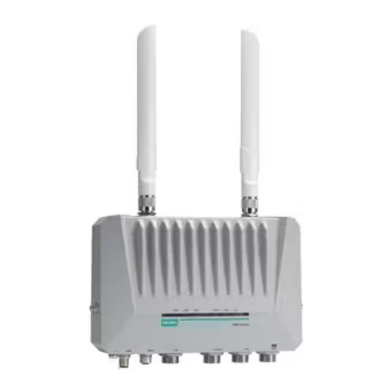
Overview The AWK-4262A Series is a Wireless AP/bridge/client with IEEE 802.11ax technology. This Series features concurrent dual-band Wi-Fi data transmissions up to 574 Mbps (2.4 GHz mode) and 1,201 Mbps (5 GHz mode) simultaneously, meeting the speed and flexibility requirements for industrial applications. In addition, the built-in dual band pass filter and the wide-temperature design ensure reliability and continuous operation in harsh environments. - Page 3 Panel Layout of the AWK-4262A 1. Antenna connector 2 (N-type) 2. Antenna connector 1 (N-type) 3. System LEDs: PWR, LAN2, LAN1, 2.4GHz, 5 GHz, SYS 4. Grounding screw (M6) 5. Power connector (5 pin M12 A-coded male) 6. Digital IO connector (8 pin M12 A-coded female) 7.
-
Page 4: Mounting Dimensions
Mounting Dimensions Wall Mounting For some applications, it may be more convenient to mount the AWK- 4262A to a wall, as illustrated below. STEP 1: Align the wall-mounting plates to the wall-mounting screw holes on the rear panel, then attach the wall- mounting plates with the M5 x 7.5 mm screws, as shown in the adjacent... -
Page 5: Din-Rail Mounting (Optional)
Do not drive the screws in all the way—leave a space of about 2 mm to allow room for sliding the wall-mounting panel between the wall and the screws. NOTE Test the screw head and shank size by inserting the screws into one of the keyhole shaped apertures of the wall-mounting plates before they are fixed to the wall. - Page 6 STEP 2: STEP 3: Insert the upper lip of the DIN-rail Press the AWK-4262A towards the kit into the mounting rail. mounting rail until it snaps into place. To remove the AWK-4262A from the DIN rail, do the following: STEP 1: Pull down the latch on the DIN-rail kit with a screwdriver.
- Page 7 STEP 2: Install the AWK-4262A with the mount assembled on a pole and fasten the screws M8 screws on the bracket of the pole-mounting kit to secure the device to the pole. PK-DC2DOF-02 Pole Mounting (Optional) It may be more convenient to mount the AWK-4262A on a pole for some applications, as illustrated below.
-
Page 8: Wiring Requirements
WARNING • This equipment is intended to be used in a Restricted Access Location, such as a dedicated computer room where only authorized service personnel or users can gain access. Such personnel must be instructed about the fact that the metal chassis of the equipment is extremely hot and may cause burns. - Page 9 NOTE Do not run signal or communications wiring and power wiring in the same wire conduit. To avoid interference, wires with different signal characteristics should be routed separately. • You can use the type of signal transmitted through a wire to determine which wires should be kept separate.
- Page 10 ATTENTION This product is intended to be mounted to a well-grounded mounting surface, such as a metal panel. The potential difference between any two grounding points must be zero. If the potential difference is NOT zero, the product could be permanently damaged.
- Page 11 Power Input ATTENTION If the AWK-4262A is connected to a motor or other similar type of equipment, be sure to use power isolation protection. Before connecting the AWK-4262A to the DC power inputs, make sure the DC power source voltage is stable. Wiring the Digital Inputs and Relay Contact (Digital Output) The AWK-4262A has two sets of digital input—DI1 and DI2.
-
Page 12: Communication Connections
Communication Connections 10/100/1000BaseT(X) and 10/100/1000/2500BaseT(X) Ethernet Port Connections The AWK-4262A has two Ethernet ports (LAN1 and LAN2) with shielded M12 8-pin female X-coded connectors located on the front panel. LAN1 is a 10/100/1000/2500BaseT(X) Ethernet port with PoE functionality, LAN2 is a 10/100/1000BaseT(X) Ethernet port. These two ports are used to connect to Ethernet-enabled devices. -
Page 13: Specifications
Color State Description Data is being transmitted at Blinking 10/100/1000 Mbps. LAN port’s 10/100/1000 Mbps link is inactive. LAN port’s 1000 Mbps link is active. Green Blinking Data is being transmitted at 1000 Mbps. LAN port’s 1000 Mbps link is inactive. LAN2 LAN port’s 10/100 Mbps link is active. -
Page 14: Software Setup
ATTENTION The AWK-4262A is NOT a portable mobile device and should be located at least 20 cm away from the human body. The AWK-4262A is NOT designed for the general public. To ensure that your AWK-4262A wireless network is safe and configured correctly, consult a well-trained technician to assist with the installation process. - Page 15 How to Access the AWK Before installing the AWK device (AWK), make sure that all items in the package checklist are provided in the product box. You will also need access to a notebook computer or PC equipped with an Ethernet port. Step 1: Select a suitable power source and plug in the AWK.
- Page 16 Step 4: Access the homepage of the AWK. Open your computer’s web browser and type https://192.168.127.253 in the address field to access the AWK’s homepage. If successfully connected, the AWK’s interface homepage will appear. Click NEXT. Step 5: Choose your country or region. Select your country or region from the drop-down list and click NEXT.
- Page 17 Step 6: Create a user account and password. Enter the username, password, and email address for your user account and click CREATE. NOTE The username and password are case-sensitive. After creating your account, you will be automatically redirected to the login screen.
-
Page 18: First-Time Quick Configuration
Step 7: Log in to the device. Enter your username and password and click LOG IN. The device will start initializing, this may take several seconds. Once the warning message has disappeared, you can log in using your username and password. - Page 19 Step 2: Set up the AWK as an AP. Click the ADD icon to create a new SSID. On the settings page, configure the SSID Status, SSID, RF Band, RTS/CTS Threshold, and Transmission Rate for the 5 GHz or 2.4 GHz band.
- Page 20 Configuring the AWK as a Client Set the operation mode of the AWK to Client mode. Go to Wi-Fi Wireless Settings and select Client from the Operation Mode drop-down list, set the SSID, and click Apply. For more detailed configurations, refer to the AWK-4262A User’s Manual.
- Page 21 Master/slave Mode Configuring the AWK as a Master Step 1: Set the operation mode of the AWK to Master mode. Go to Wi-Fi Wireless Settings and select Master from the Operation Mode drop-down list. Step 2: Set up the AWK as a Master. Click the ADD icon to create a new SSID.
- Page 22 On the settings page, configure the SSID Status, Master/AP (select Master),SSID, RF Band, RTS/CTS Threshold, and Transmission Rate for the 5 GHz or 2.4 GHz band. When finished, click NEXT. On the second SSID Settings screen, configure the SSID Broadcast Status and Security type.
-
Page 23: Fcc Statements
IMPORTANT NOTE This device is restricted to mobile configuration. To comply with FCC RF exposure compliance requirements, the antenna used for this transmitter must be installed to provide a separation distance of at least 50 cm from all persons and must not be co-located or operating in conjunction with any other antenna or transmitter. - Page 24 FCC Radiation Exposure Statement This equipment complies with FCC radiation exposure limits set forth for an uncontrolled environment. This equipment should be installed an operated with minimum distance 20 cm between the radiator & your body IMPORTANT This radio transmitter FCC ID: [SLE-AWK4262A] has been approved by FCC to operate with the antenna types listed below with the maximum permissible gain and required antenna impedance for each antenna type indicated.
- Page 25 NCC Statements 經型式認證合格之低功率射頻電機,非經許可,公司、商號或使用者均不得擅自變 更頻率、加大功率或變更原設計之特性及功能。 低功率射頻電機之使用不得影響飛航安全及干擾合法通信;經發現有干擾現象時, 應立即停用,並改善至無干擾時方得繼續使用。 前項合法通信,指依電信法規定作業之無線電通信。低功率射頻電機須忍受合法通 信或工業、科學及醫療用電波輻射性電機設備之干擾。 應避免影響附近雷達系統之操作。高增益指向性天線只得應用於固定式點對點系 統。 KC Statements 이 기기는 업무용 환경에서 사용할 목적으로 적합성평가를 받은기기로서가정 용 환경에서 사용하는 경우 전파간섭의 우려가 있습니다. - 25 -...
Need help?
Do you have a question about the AirWorks AWK-4262A Series and is the answer not in the manual?
Questions and answers