Moxa Technologies AirWorks AWK-5232 Quick Installation Manual
A/b/g/n dual-rf wireless ap / bridge/client
Hide thumbs
Also See for AirWorks AWK-5232:
- User manual (81 pages) ,
- Quick installation manual (17 pages)
Table of Contents
Advertisement
Quick Links
Download this manual
See also:
User Manual
Advertisement
Table of Contents

Related Manuals for Moxa Technologies AirWorks AWK-5232


Summary of Contents for Moxa Technologies AirWorks AWK-5232
- Page 1 Moxa AirWorks AWK-5232 Quick Installation Guide Second Edition, May 2014 2014 Moxa Inc. All rights reserved. P/N: 1802052320011 www.ipc2u.ru www.moxa.pro...
-
Page 2: Package Checklist
Overview The AWK-5232 802.11 a/b/g/n dual-RF wireless AP/Bridge/Client provides a flexible and highly reliable solution for your industrial wireless networks. The AWK-5232 is rated to operate at temperatures ranging from 0 to 60°C for standard models and -40 to 75°C for extended temperature models, and it is rugged enough for industrial applications. - Page 3 Step 3: Set up the computer’s IP address Set an IP address on the same subnet as the AWK-5232. Since the AWK-5232’s default IP address is 192.168.127.253, and the subnet mask is 255.255.255.0, you should set the IP address of the computer to 192.168.127.xxx and subnet mask to 255.255.255.0.
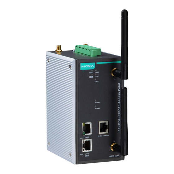
- Page 4 Panel Layout of the AWK-5232 1. Grounding screw 2. Terminal block for PWR1, PWR2, relay, DI1, and DI2 3. Reset button 4. 1B antenna port (1A and 1B are shared same RF module) 2B antenna port (2A and 2B are shared same RF module) 6.
-
Page 5: Mounting Dimensions
Mounting Dimensions DIN-Rail Mounting The aluminum DIN-Rail attachment plate should be fixed to the back panel of the AWK-5232 when you take it out of the box. If you need to reattach the DIN-Rail attachment plate to the AWK-5232, make sure the stiff metal spring is situated towards the top, as shown in the figures below. -
Page 6: Wall Mounting (Optional)
Wall Mounting (optional) For transportation applications that require an EN50155 certification report, you should purchase the optional wall mount for the AWK-5232, since the wall mount has passed EN50155 testing. The wall mount is also convenient for other applications that require mounting the AWK-5232 to a wall. -
Page 7: Wiring Requirements
Wiring Requirements WARNING Safety First! Be sure to disconnect the power cord before installing and/or wiring your Moxa AWK-5232. WARNING Safety First! Calculate the maximum possible current in each power wire and common wire. Observe all electrical codes dictating the maximum current allowed for each wire size. -
Page 8: Wiring The Redundant Power Inputs
ATTENTION This product is intended to be mounted to a well-grounded mounting surface, such as a metal panel. Wiring the Redundant Power Inputs The top two pairs of contacts of the 10-contact terminal block connector on the AWK-5232’s top panel are used for the AWK-5232’s two DC inputs. Top and front views of the terminal block connector is shown here. -
Page 9: Cable Holder Installation
Cable Holder Installation You can attach the cable holder to the bottom of the AWK-5232. This helps to keep cabling neat and avoid accidents that result from untidy cables. STEP 1: Screw the cable holder onto the bottom of the AWK-5232. STEP 2: After mounting the AWK-5232 and plugging in the LAN cable, tighten the cable along the device and wall. - Page 10 1000BaseT Ethernet Port Connection 1000BaseT data is transmitted on differential TRD+/- signal pairs over copper wires. MDI/MDI-X Port Pinouts for 8-pin RJ45 Signal TRD(0)+ TRD(0)- TRD(1)+ TRD(2)+ TRD(2)- TRD(1)- TRD(3)+ TRD(3)- RS-232 Connection The AWK-5232 has one RS-232 (8-pin RJ45) console port located on the front panel.
-
Page 11: Led Indicators
LED Indicators The front panel of the Moxa AWK-5232 contains several LED indicators. The function of each LED is described in the table below. Color State Description Front Panel LED Indicators (System) Power is being supplied from power input 1. PWR1 Green Power is not being supplied from power... -
Page 12: Specifications
Specifications WLAN Interface Standards: IEEE 802.11a/b/g/n for Wireless LAN IEEE 802.11i for Wireless Security IEEE 802.3 for 10BaseT IEEE 802.3u 100BaseTX IEEE 802.3ab for 1000BaseT IEEE 802.3at for Power-over-Ethernet IEEE 802.1D for Spanning Tree Protocol IEEE 802.1w for Rapid STP IEEE 802.1Q VLAN Spread Spectrum and Modulation (typical): •... -
Page 13: Protocol Support
TX Transmit Power MIMO: 802.11a/n (20/40 MHz): MCS15 20 MHz: Typ. 13 dBm (± 1.5 dBm) MCS15 40 MHz: Typ. 12 dBm (± 1.5 dBm) 802.11g/n (20/40 MHz): MCS15 20 MHz: Typ. 14 dBm (± 1.5 dBm) MCS15 40 MHz: Typ. 13 dBm (± -1.5 dBm) RX Sensitivity: 802.11b: -92 dBm @ 1 Mbps, -90 dBm @ 2 Mbps, -88 dBm @ 5.5 Mbps, -84 dBm... -
Page 14: Warranty
Installation: DIN-Rail mounting (standard), wall mounting (optional) Environmental Limits Operating Temperature: Standard Models: 0 to 60°C (32 to 140°F) Wide Temp. Models: -40 to 75°C (-40 to 167°F) Storage Temperature: -40 to 85°C (-40 to 185°F) Ambient Relative Humidity: 5% to 95% (non-condensing) Power Requirements Input Voltage: 12 to 48 VDC, redundant dual DC power inputs or 48 VDC Power-over-Ethernet (IEEE 802.3af compliant) -
Page 15: Technical Support Contact Information
ATTENTION Use the antennas correctly: Two dual-band 2.4 GHz & 5 GHz antennas are included with the product. Either antenna can be installed in MAIN1 or MAIN2. If you want to use a single band antenna, please use 2.4 GHz antennas for IEEE 802.11b/g mode and 5 GHz antennas for IEEE 802.11a mode.
Need help?
Do you have a question about the AirWorks AWK-5232 and is the answer not in the manual?
Questions and answers