Table of Contents
Advertisement
Quick Links
Advertisement
Table of Contents

Related Manuals for Avery Weigh-Tronix ZM 110


Summary of Contents for Avery Weigh-Tronix ZM 110
- Page 1 User Manual Model: ZM 110 BSL Bench Scale AWT35-501876 Issue AD Page 1...
- Page 2 Avery Weigh-Tronix is a registered trade mark of the Avery Weigh-Tronix group of companies. This publication was correct at the time of going to print however, Avery Weigh-Tronix reserves the right to alter without notice the specification, design, price or conditions of supply of any product or service at any time.
-
Page 3: Table Of Contents
Table of Contents 1. General information and Warnings page 6 FCC Declaration of Compliance - Déclaration de conformité..……...…………..…... Training - Formation……………………..………………………………...……………... Battery Safe Disposal - Élimination sécurisée des batteries……...………………….. Routine Maintenance - Entretien de routine……………………………………..…….. Cleaning the Machine - Nettoyage de la machine………………………….…………. Sharp Objects - Objets tranchants………………………….………………...…….. - Page 4 Checkweighing Beeper Modes…………………………..………………………….. 14 Hold Mode for Animal Weighing………………………………………..……..……… Setting the Hold Mode…………...………………….……………………………….. 4. Menus page 17 User Menu……………………..……………………………...……….………….……..…. User Menu Levels………………….………………...……….……………………..… User Functions Descriptions [UF].………………….……….…………………..…… Supervisor Menu..………………………….……………..………………….……..……. Quick Calibration Menu……..………………………..……………………….……..……. 5. Scale Configuration [LF 2] page 19 6. RS232 Communications [UF-6] page 19 7.
- Page 5 Manual revision history Current Issue Date Created Details of Changes May 2019 Aug 2019 RS232 Kit added and Chapter 6 amended Jan 2020 Check Counting, UF5 amended Feb 2023 Hold Mode, UF5 updated Please be aware this product contains a lead acid battery which MUST be removed and disposed of safely prior to any disposal of the scale.
-
Page 6: General Information And Warnings
1. General Information and Warnings 1.1. FCC Declarations of Compliance - FCC Déclaration de conformité United States This equipment has been tested and found to comply with the limits for a Class A digital device, pursuant to Part 15 of the FCC Rules. These limits are designed to provide reasonable protection against harmful interference when the equipment is operated in a commercial environment. -
Page 7: Training - Formation
1.2. Training - Formation Do not attempt to operate or complete any procedure on a machine unless you have received the appropriate training or read the instruction books. Ne pas tenter d’utiliser la machine ou lui appliquer une quelconque procédure sans avoir reçu une formation adaptée ou lu les manuels d’instruction. -
Page 8: Introduction
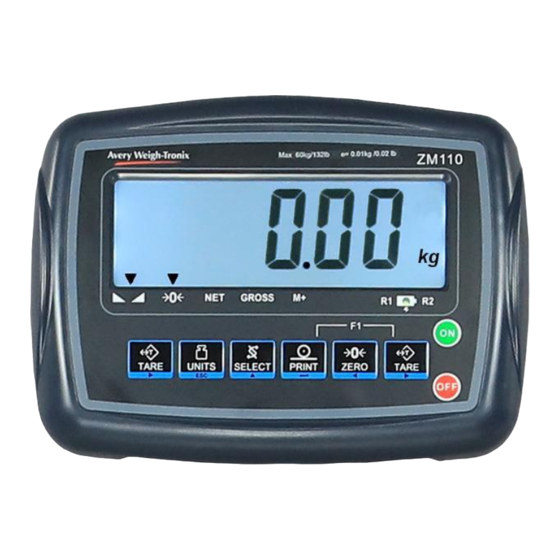
2. Introduction The ZM110 is a general-purpose indicator ideal for connecting to most bench and floor scales. This indicator can easily be desk or pole mounted and comes with a power adaptor along with a rechargeable lead acid battery to allow the scale to be used in applications where power outlets are limited. -
Page 9: Scale Installation
2.2.2 Scale Installation 1. Attach the support column to the bracket at the back of the scale base using the three mounting screws. Use a 3mm hex (Allen) key to tighten the screws. See Figure 3. Fig. 3 Insert column into bracket and secure with three screws 2. -
Page 10: Battery Operation
2.3. Battery Operation The ZM 110 can be operated from a 6V 4Ahrs battery located inside the indicator or plugged into an acceptable power outlet. Battery life is approximately 107 hours with the backlight off. When the battery needs charging this symbol, , appears in the upper left corner of the weight display. -
Page 11: Operation Keys
2.5.2. Operation Keys Keys are shown below along with their functions. Some keys have secondary functions. Press and hold the OFF key to turn off the scale. “oFF” will be displayed for 2 seconds. Press the ON key to turn on the scale. The scale will run through a display test before displaying 0.000. -
Page 12: Scale Operation
3. Scale Operation This section covers the scale operations of simple weighing, counting and hold. The steps for various kinds of weighing are explained in the following pages. A warm-up time of 15 minutes is required to stabilize the measured values. 3.1. -
Page 13: Sampling Parts Prior To Counting
3.3.1. Sampling Parts Prior to Counting Follow these steps to count items using the sampling method. 1. Power up and if necessary Zero the scale by pressing the ZERO key. If the weight change is within the Zero window area the display will show 0.000. Decimal positions available may vary. 2. -
Page 14: Setting The Checkweighing Limits
3.4.1. Setting the Checkweighing Limits When the scale is ON, press the PRINT and TARE keys together; UF-1 will be displayed. Press TARE (►) key; UF-2 will be displayed. iii. Press PRINT(↵) key; Enter or edit the LO limit value by pressing the ZERO(◄) and/or TARE (►) keys to move the flashing digit left or right and press the SELECT (▲) key to increase the numeric value;... -
Page 15: Hold Mode For Animal Weighing
3. Place the item(s)/animal to be weighed/counted on the scale platform. The indicator captures the weight. The indicator freezes the stable weight. 4. Removing the item(s)/animal from the scale platform will clear the hold weight. 5. Repeat the steps above for other Hold weighments. To disable the Hold mode, open the User Menu and select the Hold function [UF-5], option [Hold 0]. -
Page 16: Setting The Hold Mode
3.5.2 Hold Mode Examples PCt = 20 divisions, stability window timE =16 weight readings to be taken from within the stability window The hold weight displayed is the last weight reading taken from within the stability window. Note: a smaller PCt value sets a tighter stability window in which the stable weight has to be captured timE number of times. -
Page 17: Menus
4. Menus There are three menus that allow configuring, enabling and executing specific functions or options. pages • User Menu UF – 1 ~ 11 • Supervisor Menu See Service Manual ZM110_s_en_501813.pdf • Quick Calibration Menu See Service Manual ZM110_s_en_501813.pdf 4.1. -
Page 18: User Functions Descriptions [Uf]
4.1.2. User Functions Descriptions [UF] There are 9 Setup Functions. UF-1 Diagnostic: use this menu to check or verify the performance of the indicator. The diagnostic tests available include: Scale A to D to view output from the connected scale base or load device, Internal D-Value, and Battery Voltage. -
Page 19: Supervisor Menu
4.2. Supervisor Menu In the Supervisor Menu there are various submenus available to configure system parameters, specific sections of the operating modes and the calibration feature. See Service Manual ZM110_s_en_501813.pdf 4.3 Quick Calibration Menu It is recommended to perform only the very first calibration following the function LF 1 in the Supervisor Menu. - Page 20 Loadcell Pinouts LOADCELL connection (for indicator) PIN 1 : Ex + PIN 2 : Sense + PIN 3 : Ex- PIN 4 : Sense - PIN 5: Sig + PIN 6 : GND PIN 7 : Sig – AWT35-501876 Issue AD Page 20...
- Page 21 AWT35-501876 Issue AD Page 21...
Need help?
Do you have a question about the ZM 110 and is the answer not in the manual?
Questions and answers