
Related Manuals for Avery Weigh-Tronix Reflex HP Series


Summary of Contents for Avery Weigh-Tronix Reflex HP Series
-
Page 1: User Instructions
Electronic Balance User Instructions Reflex HP Series Precision Balances READ AND UNDERSTAND THIS MANUAL BEFORE OPERATION. English 76103-918 Issue 1 16-03-2004 *76103-918*... -
Page 2: Notation Conventions
Notation Conventions dNo. Note This instruction manual uses the following notation conventions to indicate Safety Precautions and additional information. Indicates a potentially hazardous situation that may Caution result in injury to personnel or equipment damage. Provides additional information needed to properly Note use the balance. -
Page 3: Safety Precautions
This includes areas where the balance is exposed to dust or flammable gases and liquids. • Use the AC adapter specified by Avery Weigh-Tronix. To prevent electric shock, never disassemble the AC adapter. The AC adapter is designed for indoor use. Do not use the AC adapter in exterior environments or where it may be splashed by water. -
Page 4: Declaration Of Conformity
A copy of the original signed declaration for this instrument is available from: Avery Weigh-Tronix, Foundry Lane, Smethwick, West Midlands B66 2LP England - III -... - Page 5 Low Voltage Directive 73/23/EEC The applicable harmonised EN60950, EN45501, EN55022, standards are: EN55024, EN61000-3 A copy of the original signed declaration for this instrument is available from: Avery Weigh-Tronix, Foundry Lane, Smethwick, West Midlands B66 2LP England - IV -...
- Page 6 When Avery Weigh-Tronix balances are integrated with laboratory software by means of our WindowsDirect function, no communication software is required or used. The Avery Weigh-Tronix balance functions as a primary device in the system, just as a keyboard, mouse or other data entry hardware does.
-
Page 7: Table Of Contents
Contents Notation Conventions Safety Precautions Declaration Of Conformity 1. Introduction ・・・・・・・・・・・・・・・・・・・・・・・・・・・・・・・・・・・・・・・・・・・・・・・・・・・・・・ 2. Components, Names and Functions ・・・・・・・・・・・・・・・・・・・・・・・・・・・・・・・・ Components ・・・・・・・・・・・・・・・・・・・・・・・・・・・・・・・・・・・・・・・・・・・・・・・・・・・・・・・・・・・・・・・・ Key Panel and Operation ・・・・・・・・・・・・・・・・・・・・・・・・・・・・・・・・・・・・・・・・・・・・・・・・・・・・・ Balance Display and Functions ・・・・・・・・・・・・・・・・・・・・・・・・・・・・・・・・・・・・・・・・・・・・・・・・ 3. Specifications ・・・・・・・・・・・・・・・・・・・・・・・・・・・・・・・・・・・・・・・・・・・・・・・・・・・・ 4. Installation ・・・・・・・・・・・・・・・・・・・・・・・・・・・・・・・・・・・・・・・・・・・・・・・・・・・・・・・ Choosing the Installation Site ・・・・・・・・・・・・・・・・・・・・・・・・・・・・・・・・・・・・・・・・・・・・・・・・・ Unpacking and Delivery Inspection ・・・・・・・・・・・・・・・・・・・・・・・・・・・・・・・・・・・・・・・・・・・・・... - Page 8 Menu Item Selection Procedure ・・・・・・・・・・・・・・・・・・・・・・・・・・・・・・・・・・・・・・・・・・・・・・・ Setting Numeric Values ・・・・・・・・・・・・・・・・・・・・・・・・・・・・・・・・・・・・・・・・・・・・・・・・・・・・・・ Related Useful Functions ・・・・・・・・・・・・・・・・・・・・・・・・・・・・・・・・・・・・・・・・・・・・・・・・・・・・・ 7.5.1 Last Menu Recall ・・・・・・・・・・・・・・・・・・・・・・・・・・・・・・・・・・・・・・・・・・・・・・・・・・・・・ 7.5.2 Returning to the Default Settings (menu reset) ・・・・・・・・・・・・・・・・・・・・・・・・・・・ 7.5.3 Menu Lock ・・・・・・・・・・・・・・・・・・・・・・・・・・・・・・・・・・・・・・・・・・・・・・・・・・・・・・・・・・ Navigating the Menu Map ・・・・・・・・・・・・・・・・・・・・・・・・・・・・・・・・・・・・・・・・・・・・・・・・・・・・・ 7.6.1 Specifications of the RS-232C Connector ・・・・・・・・・・・・・・・・・・・・・・・・・・・・・・・ 7-12 7.6.2 Table of Unit Conversion Information ・・・・・・・・・・・・・・・・・・・・・・・・・・・・・・・・・・・...
- Page 9 11.4 Tracking ・・・・・・・・・・・・・・・・・・・・・・・・・・・・・・・・・・・・・・・・・・・・・・・・・・・・・・・・・・・・・・・・・・・・ 11-2 12. Units ・・・・・・・・・・・・・・・・・・・・・・・・・・・・・・・・・・・・・・・・・・・・・・・・・・・・・・・・・・・・ 12-1 12.1 Unit Display Set-up ・・・・・・・・・・・・・・・・・・・・・・・・・・・・・・・・・・・・・・・・・・・・・・・・・・・・・・・・・・ 12-1 12.2 Percentage (%) Conversion ・・・・・・・・・・・・・・・・・・・・・・・・・・・・・・・・・・・・・・・・・・・・・・・・・・・ 12-2 13. Enhancing Productivity ・・・・・・・・・・・・・・・・・・・・・・・・・・・・・・・・・・・・・・・・・・・ 13-1 13.1 Checkweighing and Target Display ・・・・・・・・・・・・・・・・・・・・・・・・・・・・・・・・・・・・・・・・・・・・ 13-1 13.1.1 Checkweighing (Comparator) Display Type 1 ・・・・・・・・・・・・・・・・・・・・・・・・・・・・ 13-2 13.1.2 Checkweighing (Comparator) Display Type 2 ・・・・・・・・・・・・・・・・・・・・・・・・・・・・...
- Page 10 16. Maintenance and Transportation ・・・・・・・・・・・・・・・・・・・・・・・・・・・・・・・・・・・ 16-1 16.1 Maintenance ・・・・・・・・・・・・・・・・・・・・・・・・・・・・・・・・・・・・・・・・・・・・・・・・・・・・・・・・・・・・・・・・ 16-1 16.2 Moving the Balance ・・・・・・・・・・・・・・・・・・・・・・・・・・・・・・・・・・・・・・・・・・・・・・・・・・・・・・・・・・ 16-1 17. Troubleshooting ・・・・・・・・・・・・・・・・・・・・・・・・・・・・・・・・・・・・・・・・・・・・・・・・・・ 17-1 17.1 General Display ・・・・・・・・・・・・・・・・・・・・・・・・・・・・・・・・・・・・・・・・・・・・・・・・・・・・・・・・・・・・・ 17-1 17.2 Error Display ・・・・・・・・・・・・・・・・・・・・・・・・・・・・・・・・・・・・・・・・・・・・・・・・・・・・・・・・・・・・・・・・ 17-2 17.3 Troubleshooting ・・・・・・・・・・・・・・・・・・・・・・・・・・・・・・・・・・・・・・・・・・・・・・・・・・・・・・・・・・・・・ 17-3 17.4 LCD (Liquid Crystal Display) Check ・・・・・・・・・・・・・・・・・・・・・・・・・・・・・・・・・・・・・・・・・・・・ 17-3 - iv -...
-
Page 11: Introduction
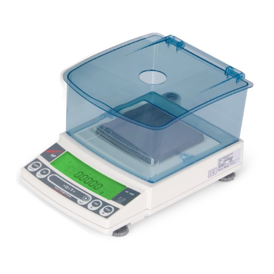
1. Introduction The Avery Weigh-Tronix Reflex HP series of precision balances give you high performance, fast response, and durability. Features available include multiple units of measure, piece counting, checkweighing functions, auto print, and GLP/GMP/ISO output including date and time data from a built-in clock. - Page 12 Trademarks and acknowledgements Avery, Avery Berkel, Avery Weigh-Tronix are registered trademarks in certain jurisdictions and owned and registered by companies within the Avery Weigh-Tronix Group. All brands and product names used within this document are trademarks or registered trademarks of their respective holders.
-
Page 13: Components, Names And Functions
Components, Names & Functions Components (Connectors on the back) 2 - 1... -
Page 14: Key Panel And Operation
Key Panel and Operation [POWER] key [CAL] key [O/T] key [UNIT] key [PRINT] key Function of the keys During Weighing Press Once and Release Press and Hold for About 3 Seconds Switches between the operation and standby Exits the application function and returns to the [POWER] modes. -
Page 15: Balance Display And Functions
Balance Display and Functions Display Name Description Indicates that the weighed value is stable. (*1) In menu item selection, indicates Stability mark currently selected item. Tare symbol Indicates that a Pretare value has been set.(*2) Illuminates during span calibration. In menu selection, indicates setting related to calibration. -
Page 16: Specifications
3. Specifications Reflex HP Series with internal Calibration HP Series Model HP420C HP620C HP2200C HP4200C HP6200C HP820C HP4200SC HP8200C Capacity 420g 620g 2200g 4200g 6200g 820g 4200g 8200g Minimum display 0.001g 0.001g 0.01g 0.01g 0.01g 0.01g 0.1g 0.1g Calibration range... - Page 17 Reflex HP Series – EC Trade approved with internal Calibration Reflex HP Series HP820CT HP420CT HP620CT HP8200CT HP2200CT HP4200CT HP6200CT Trade Approved Models Accuracy class Ⅱ Ⅰ Ⅱ Ⅰ Capacity 820g 420g 620g 8200g 2200g 4200g 6200g Verification scale interval (e) 0.1g...
-
Page 18: Installation
4. Installation Choosing the Installation Site Power supply • Select an installation site that is near a power source to ensure that the attached AC adapter is used properly. If this is not possible, an optional battery pack is available as a special accessory. •... - Page 19 • Extreme temperature, temperature changes or humidity • Corrosive or flammable gasses • Dust,wind, electromagnetic waves, or magnetic ´ fields fields Note Using a verified balance as a legal measuring instrument in the EU: The balance must be used within the temperature range indicated on the verification label.
-
Page 20: Unpacking And Delivery Inspection
Unpacking and Delivery Inspection Unpack and remove all the items from the delivery box. Check if all the listed items are present and nothing has been damaged. Contact your local sales representative in case of damaged or missing items. Standard Packing List (Number of item) Small pan model Small pan model Large pan model... -
Page 21: Installation
Installation (Start at step 3 when installing a HP (external calibration) series balance. You will need a Pozidrive screw driver for a HPxxxC (internal calibration) series balance.) Place the balance main body upside down. (HPxxxC only) Caution Do not operate step 2 with the balance placed on its side. - Page 22 Adjust the level. This balance has four feet, three of which are adjustable. For efficient level adjustment, follow the procedure below. (1) First, verify that all three leveling screws are at their shortest point. (2) While lightly pressing down on the left front of the balance, turn both of the front leveling screws to bring the air bubble into the center circle of the level indicator.
- Page 23 Note Using a verified balance as a legal measuring instrument in the EU: Legal regulations require a verified balance to be sealed. This control seal is a self-destructive adhesive label. If you attempt to remove it, this seal is irreparably damaged thereby invalidating the verification. The balance must then be re-verified before it is used for legal measurements.
-
Page 24: Turning On The Power
Turning On the Power Insert the plug of the AC adapter into the DC IN connector on the rear of the balance. Insert the AC adapter into the power source. The balance self-check is activated and the following messages are displayed in the order indicated. [HELLo], [CHE 5], [CHE 4], [CHE 3], [CHE2], [CHE1], [CHE0], whole lighting, [oFF] ([CHE 5] and [CHE 4] are not displayed for the HPxxx series). -
Page 25: Span Calibration
Span Calibration Note Using a verified balance as a legal measuring instrument in the EU: Span calibration must be performed once the balance is installed and before using the balance as a legal measuring instrument in the EU. Span calibration must be performed with the internal calibration weight to maintain the verification valid. - Page 26 HP series [Span Calibration Using External Weights] Verify that the balance is in gram-display and unload the sample from the pan. Press the [CAL] key once. “E-CAL” is displayed. Press the [O/T] key. The value of the correct calibration weight to be (Example) loaded is displayed and blinks.
-
Page 27: Basic Operation
5. Basic Operation Weighing If a weighing vessel (tare) is used, place it on the pan and wait for the stability mark to illuminate. Press the [O/T] key to zero the display. (This operation is called “taring”.) Place the object to be weighed on the pan. Read the displayed value after the stability mark is displayed. -
Page 28: Changing The Default Unit Display
Changing the default Unit Display Every time the [UNIT] key is pressed, the unit display changes sequentially among those set-up in 12.1 Unit Display Set-up. Gram, %, and PCS have been set-up as default units before delivery. Notes • Before a unit can be displayed it must be registered in 12.1 Unit Display Set-up. •... -
Page 29: Windowsdirect Function
6. WindowsDirect Function Introduction: Experience it! The Reflex HP series balance can transfer data directly to a personal computer running Lotus 1-2-3, Excel, or other applications running on a Windows* operating system, as if the displayed value were typed from the keyboard. This function is called WindowsDirect. Because this function directly accesses the Windows operating system, communication software-installation troubles are eliminated. -
Page 30: Cable Connection
6.2.2 Cable Connection Verify the balance display is “STAND-BY”. Turn off the computer and disconnect the power cord from the balance. Connect the RS-232C cable to the balance. Connect the RS-232C cable to the computer. 6.2.3 Setting Up the Computer (leave the balance unplugged) Turn ON the power to the computer and start Windows*. - Page 31 Select the serial port corresponding to the RS-232C port of your personal computer. (Serial port: any one of COM1 to 4. Usually, COM1) Select a Baud rate of 300. Click OK. 10 Click Apply and wait. 11 Click OK. 12 Click Start, point to Shut Down then select Restart the computer?.
-
Page 32: Start And Checking Operation
6.2.4 Start and Checking Operation Start Windows. After Windows has completely started, connect power cable from the AC adapter to the balance. When the display shows “off”, press the [POWER] key to show the mass display. Note Turning on the balance before Windows is completely activated may cause incorrect operation. -
Page 33: Troubleshooting
• Avery Weigh-Tronix is not liable for any direct or indirect problems caused by this function. It is recommended that important data or programs on your computer be backed-up before using this function. - Page 34 When the WindowsDirect Function Intermittently Malfunctions: • Use a communication speed of 300bps. Depending on the processing ability of the computer, this function may operate incorrectly if communication speed is too high. • Send the next data only after the current one is displayed on the screen. Depending on the processing ability of the PC, this function may operate incorrectly if the interval of data transmission is too short.
-
Page 35: Notes On Windowsdirect
Notes on WindowsDirect Compatibility Notification Regarding Linking of “WindowsDirect” Function with Windows 95 Version 4.00.950B Microsoft Corporation announces that, when a personal computer’s SerialKey Devices are set up, an OE error may occur, depending on the Windows 95 version. Before setting up your personal computer for “Linking with Windows 95” function of Avery Weigh-Tronix´s balances, be sure to check your Windows 95 version and take appropriate precautionary measures according to this instruction, whenever required. - Page 36 2. Precautionary Measures For Microsoft Windows 95 ver. 4.00.950B only. Close all of active software applications. Select [Start], designate the file name, and click on [Run...]. Enter “regedit” in the “Open:” field via the keyboard. Click [OK], and the Registry Editor will start up. Double-click “HKEY_LOCAL_MACHINE”...
-
Page 37: Menu Item Selection
7. Menu Item Selection What is the Menu? The Reflex HP series balance has many functions that can be selected to meet the requirements of the user. Menu Item selection is used to program these functions. Menu Map The menu of the Reflex HP balance consists of seven groups and four levels. The Menu Map shows the structure clearly with menu item numbers to help access the desired function. -
Page 38: Menu Item Selection Procedure
Menu Item Selection Procedure This instruction manual identifies each menu item by a number. For example, the menu items of “Stability Detection Band” of “section 11. Environment” are through . These numbers are also shown on the Menu Map in section 7.6 and on the pull out Explanatory Operation Sheet. Find the function to be programmed in the Menu Map, referring to the item number in square, To reach the item, operate the keys on the balance. - Page 39 Press the [O/T] key to select this item. “SEt” is displayed and the stability mark now appears with “Eb-4”. Return to the desired menu by pressing the [POWER] key. If pressed and held, it returns to the gram-display. Once the menu items have been set based on the installation environment and weighing purpose, it is not necessary to select the menu items each time the balance is used.
-
Page 40: Setting Numeric Values
Setting Numeric Values Some of Reflex HP series balance menu items require numeric value setting. For example, external calibration weight input, thresholds for checkweighing, and reference density in specific gravity measurements (see 10.2, 10.3, 13.1, 13.5, 14.1, 14.2, 14.4 for detail of each item.) The values can be set using the balance keys. -
Page 41: Related Useful Functions
Related Useful Functions 7.5.1 Last Menu Recall This function is convenient when an application requires frequent changes to a specific menu item. During mass display or menu selection, press and hold the [CAL] key for approximately three seconds. The last menu item that was changed or set is displayed. 7.5.2 Returning to the Default Settings (menu reset) The procedure below describes how to reset the menu and return to the default settings. -
Page 42: Menu Lock
7.5.3 Menu Lock The Reflex HP series balances have a “Menu Lock” function that locks the menu selections to avoid accidental changes. WindowsDirect setting (6.2.1) is also locked. The menu lock is toggled ON and OFF by pressing the [CAL] key during “oFF” display that appears after power is supplied to the balance. -
Page 43: Navigating The Menu Map
NAVIGATING THE MENU MAP Menu Map • Press the [CAL] key to access the menu. • Press the [CAL] key to scroll to the next item on a menu level. • Press the [O/T] key to select the current item, or to move to the next menu level. •... - Page 44 flashing flashing flashing flashing flashing flashing flashing flashing flashing flashing flashing flashing flashing Continued No. : Menu item number : Default settings *Not applicable to a verified balance as a legal measuring instrument in the EU 7 - 8...
- Page 45 flashing flashing flashing flashing flashing flashing flashing flashing flashing Continued No. : Menu item number : Default settings *Not applicable to a verified balance as a legal measuring instrument in the EU 7 - 9...
- Page 46 flashing flashing flashing flashing flashing flashing Continued No. : Menu item number : Default settings *Not applicable to a verified balance as a legal measuring instrument in the EU 7 - 10...
- Page 47 flashing flashing flashing flashing flashing flashing flashing flashing No. : Menu item number Returns to flashing : Default settings 7 - 11...
-
Page 48: Specifications Of The Rs-232C Connector
7.6.1 Specifications of the RS-232C Connector Pin number Name Function Remarks Frame ground Data output Data input Internal connection with CTS Internal connection with RTS Handshake (receiving) Signal grounding Blank Foot switch TARE External TARE To GND Blank Blank Blank Spare Extension input Connection is prohibited... -
Page 49: Table Of Unit Conversion Information
7.6.2 Table of Unit Conversion Information Displayed during weighing Displayed during Unit Display Set-up (See 12.1) Display Minimum Illuminated display in the unit Conversion Center section triangular symbols in Menu item (models with Unit Unit Coefficient (segmented the right end row of number minimum display display... -
Page 50: Built-In Clock Set-Up
8. Built-in Clock Set-up The built-in clock has to be set up in advance if a calibration record is to be produced or Clock-CAL function is to be used. Date Select menu item and set the last two figures of the year, month and day, using the [UNIT] and [PRINT] keys. -
Page 51: Setting Display During Stand-By
Setting Display During Stand-by Determine what is to be displayed during stand-by. To display the time during stand-by, select menu item To display the date during stand-by, select menu item To display neither during stand-by, select menu item Notes Convenient Functions of Time Display The following functions are available when the time is displayed during stand-by. -
Page 52: Display Settings
9. Display Settings Bar graph display The relative amount of the load on the pan is displayed in the bar graph. This feature helps to prevent errors due to OL (overload) status. This is called Full Scale mode. This display can not be used with the Checkweighing or Target mode. -
Page 53: Calibration
10. Calibration 10.1 What is calibration? Calibration is required to accurately weigh items with an electronic balance. Calibration should be performed: • When the location of the balance is changed, even within the same room. • When the room temperature changes considerably. •... -
Page 54: Calibration Execution
10.2 Calibration Execution Notes • Setting before shipment is as the following: Reflex HPxxxC series: Span calibration using the built-in weight Reflex HPxxx series : Span calibration using external weights The type of calibration can be changed (See 10.3). • Calibration will not be performed when the weight on the pan is not near zero, or the balance is not stable. -
Page 55: Calibration Check Using The Built-In Weight (Hpxxxc Series Only)
10.2.2 Calibration Check Using the Built-in Weight (Reflex HPxxxC Series only) Not applicable to a verified balance as a legal measuring instrument in the EU Verify that the balance is in mass display and that the pan is empty. Press the [CAL] key once to display “i-tESt”. (If “i-tESt”... -
Page 56: Span Calibration Using External Weights
10.2.3 Span Calibration Using External Weights Not applicable to a verified balance as a legal measuring instrument in the EU Verify that the balance is in mass display and that the pan is empty. Press the [CAL] key once. “E-CAL” is displayed. (If “E-CAL”... -
Page 57: Calibration Check Using External Weights
10.2.4 Calibration Check Using External Weights Not applicable to a verified balance as a legal measuring instrument in the EU Verify that the balance is in mass display and that the pan is empty. Press the [CAL] key once to display “E-tESt”. (If “E-tESt”... -
Page 58: Calibration Setting
10.3 Calibration Setting 10.3.1 Selecting the Calibration Type Not applicable to a verified balance as a legal measuring instrument in the EU Set the calibration type that will be used in Calibration Execution. To set up “Span calibration using the built-in weight”,(HPxxxC only) Select menu item To set up “Calibration check using the built-in weight”,(HPxxxC only) Select menu item To set up “Span calibration using external weights”, Select menu item... -
Page 59: Clock-Cal Fully-Automatic Calibration (Hpxxxc Series Only)
10.3.3 Clock-CAL Fully-automatic Calibration (HPxxxC series only) Span calibration is performed automatically using the built-in calibration weight at up to 3 specific, preset times during each day. The user selects the times. This function is named Clock-CAL. It is possible to set up to three specific times for Clock-CAL (“ACALt1”, “ACALt2”, and “ACALt3”). Use the 24 hour system to set menu items , and . -
Page 60: Pcal: Calibration Of The Built-In Weight (Hpxxxc Series Only)
10.3.4 PCAL: Calibration of the Built-in Weight (HPxxxC series only) Not applicable to a verified balance as a legal measuring instrument in the EU PCAL is used to calibrate the built-in weight to a standard calibration weight that is correctly adjusted, traceable and/or certified. -
Page 61: Pcal Password Setting (Hpxxxc Series Only)
Notes • “SEt” is displayed during the process. Leave the balance in a stable state until the mass display appears as in step 5. • In PCAL, the value of the “weight to be loaded” cannot be changed. • Set the PCAL password using menu item 10.3.5 PCAL Password Setting (HPxxxC series only) Not applicable to a verified balance as a legal measuring instrument in the EU... -
Page 62: For Glp/Gmp/Iso Conformance
10.4 For GLP/GMP/ISO Conformance These settings should be made by the administrator. 10.4.1 Calibration Report Setting Calibration report setting turns function ON/OFF. Use this to generate and output a calibration report as for GLP, GMP, or ISO9000. An electronic printer (optional accessory) is required to print the report. To create calibration report, Select menu item To turn off calibration report function,... -
Page 63: Environment
It is possible to match the stability of the display and the degree of response with the requirements of specific applications or the installation environment. One of five modes can be selected. Note that adjustments for stability and response conflict with each other, although the Reflex HP series is designed to meet both. -
Page 64: Stability Detection Band
11.3 Stability Detection Band *Not applicable to a verified balance as a legal measuring instrument in the EU The conditions for indicating balance stability can be selected. If “1 count” is selected, when the display has remained constant (within one display count), the balance is regarded as stable and the stability mark illuminates. -
Page 65: Units
Carat is not available for HP820CT and HP8200CT models. The Reflex HP series balance can display weighed results in various weighing units. Refer to 7.6.2 for details. It is possible to display units other than “g”. Press... -
Page 66: Percentage (%) Conversion
12.2 Percentage (%) Conversion Set the % unit with menu item if it is not set up. The % unit is set before shipment. Press the [UNIT] key several times in the mass display until the % unit is displayed. Setting the 100% reference Press the [O/T] key to tare the balance. -
Page 67: Enhancing Productivity
Zero Range setting (refer to 13.5). 13.1 Checkweighing and Target Display The Reflex HP series balance has an analog bar graph located on the left side of the display. This graph can be conveniently used for checkweighing or cumulative weighing. -
Page 68: Checkweighing (Comparator) Display Type 1
13.1.1 Checkweighing (Comparator) Display Type 1 This is the best mode to determine pass or failure judgment based on the sample weight. Select menu map item Displays in use Set the upper threshold value, which corresponds to the upper triangle mark, with menu item Set the lower threshold value, which corresponds to the lower triangle mark, with menu item Note... -
Page 69: Target Mode
13.1.3 Target Mode This mode is useful for constant amount weighing of liquid or judgment of excess and shortage. The target value is the numeric value that is the desired amount in the unit that is used for weighing. The limit value is the numeric amount above or below the target value that is acceptable. -
Page 70: Piece Counting (Pcs)
13.2 Piece Counting (PCS) Set up the PCS with menu item if it is not set. (The PCS unit is set before shipment.) Press the [UNIT] key several times in the mass display until the PCS is displayed. Load the container and press the [O/T] key to tare the balance. -
Page 71: Auto Print
13.3 Auto Print Auto Print function allows output of the data automatically without pressing the [PRINT] key for each sample. The “Auto-Print” symbol is illuminated when the Auto Print function is activated. Six types of Auto Print are possible. See 13.5 for Zero Range setting. Print on loading: Select menu item Load the sample when the value displayed is within the Zero Range. -
Page 72: Auto Zero
Notes • During continuous output, the Communication symbol may appear to remain lit. If the transfer speed of the data output is slow, the display may flash. Increase the transfer speed as much as possible and set the handshake off (menu item •... -
Page 73: Taring/Printing At Stability
Note When a Pretare value is set, the value to determine that there is “no load” becomes “- Pretare ± Zero Range” during gram-display. The Zero Range function works as expected when attempting to weigh and Auto Print the mass of a bottled sample during gram-display. 13.6 Taring/Printing at Stability Not applicable to a verified balance as a legal measuring instrument in the EU Determine if the balance should wait for stability before printing when the [PRINT] key is pressed or... -
Page 74: Pretaring Value
13.7 Pretaring Value Not applicable to a verified balance as a legal measuring instrument in the EU Notes • If the weight of the tare (container) varies, accurate measurement with Pretaring Value function cannot made. • Pretaring Value function cannot be used with Peak Hold, Auto-Memory and Zeroing, Animal Weighing, or Auto function. -
Page 75: Application Functions
14. Application Functions Application measurement functions are described in this chapter. Only one of the functions in the menu group 4 (Refer to 7.3) ( ) can be used at a time. When one of the functions in menu group 4 is to be used with a weighing unit other than gram, select the function from the gram-display first. - Page 76 Hook the hanging pan, and then immerse the hanging pan in the tank filled with the liquid of known specific gravity (or density). From mass display, press the [UNIT] key several times until ▼d (inverse triangle and “d”) is displayed. Press the [O/T] key.
-
Page 77: Liquid Density Measurement
14.2 Liquid Density Measurement Liquid density measurement refers to the measurement of the weight of a reference solid of a known volume in air and in the sample liquid. Density of the liquid is calculated from these two values. The display unit for liquid density is “d”. The data output unit is DL. Note Use of the optional SMK-101, or SMK-102 Specific Gravity Measurement Kit is recommended for efficient measurements. - Page 78 Load the reference weight on the hanging pan and immerse it in the sample liquid. The density of the sample liquid is displayed. Repeat steps 5 through 8 for each additional sample. Notes • Up to four decimal places are displayed for density. When it is not possible to stabilize the balance in all 4 decimal places, use the 1d/10d switching function.
-
Page 79: Peak Hold
14.3 Peak Hold Not applicable to a verified balance as a legal measuring instrument in the EU Measures the displayed peak value. The “P” symbol (“P” of Auto-Print symbol) is illuminated when the Peak Hold function is activated. “Peak value” is the highest or lowest stable value displayed after the display has changed beyond five times the Zero Range. -
Page 80: Interval Timer
14.4 Interval Timer Not applicable to a verified balance as a legal measuring instrument in the EU Automatically outputs the displayed value at preset intervals. The “T” symbol (“T” of the Tare symbol) is illuminated when the Interval Timer is activated. Select menu item and set the output interval (00:01 = 1 sec to 99:59 = 99 minutes 59 seconds). -
Page 81: Auto-Memory And Zeroing
14.5 Auto-Memory and Zeroing Not applicable to a verified balance as a legal measuring instrument in the EU Used to weigh a large number of individual samples. The “Auto-Memory and Zeroing” symbol is illuminated when this function is active. Select menu item Load the weighing vessel and press the [O/T] key in the Auto-Memory and Zeroing standby state (The “Auto-Memory and Zeroing”... -
Page 82: Animal Weighing
14.6 Animal Weighing Not applicable to a verified balance as a legal measuring instrument in the EU Designed for weighing animals. The Animal symbol is illuminated when the Animal Weighing mode is active. Select menu item Load the weighing vessel and press the [O/T] key. Note Data may be output when the weighing vessel is loaded. - Page 83 Notes • Standby state is not available in the Animal Weighing mode. • Press the [POWER] key to initiate the power supply standby state. • On the premise of weighing animated objects, the stability detection band is automatically extended in the Animal Weighing mode. Reproducibility of the measurement data is slightly less than with other modes.
-
Page 84: Connecting Peripheral Instruments
15. Connecting Peripheral Instruments (For WindowsDirect, refer to 6. “WindowsDirect Function”) A variety of peripheral instruments are available for use with the Reflex HP series balance, such as an electronic printer, keyboard or personal computer. This chapter describes how to connect and communicate with peripheral instruments. -
Page 85: Personal Computer - Rs-232C
15.2.1 Connecting the Cable Caution Signals other than RS-232C are also output by the Reflex HP series balances through the RS-232C/AUX connector. If these signal lines are incorrectly connected, damage may occur to the personal computer or balance. Correctly connect an appropriate cable for communication between the balance and personal computer. -
Page 86: Data Format
15.2.2 Data Format The following explanation is applied when menu item (Format EB type) is selected. For other formats, refer to the data corresponding to the compatible machine. Note indicates space code and <delimiter> indicates delimiter code. For the measured value First character: Minus: '-' Non-minus: space 2nd to 11th characters:... -
Page 87: Using Command Codes
15.2.3 Using Command Codes Note If communication conditions are incorrectly set, a communication error message “ComErr” is displayed. Commands that end with a number, character, or symbol other than [=]: Transmit to the balance with a delimiter for each command code. Example 1: PRINT<CR>... - Page 88 Example 7: #=12.345.67 <CR> A personal computer can instruct the weighing and display a specific number on the balance. With the commands in Example 6 &7, [#2.56] and [#12.345.67] are displayed on the balance. When the operator presses the [PRINT] key, the character string '2-56<CR>' and '12-345-67<CR>...
- Page 89 (ii) Commands related to operation keys POWER Equivalent to the [POWER] key. Equivalent to the [POWER] key. MENU Equivalent to the [CAL] key. TARE Equivalent to the [O/T] key. Equivalent to the [O/T] key. UNIT Equivalent to the [UNIT] key. PRINT Equivalent to the [PRINT] key.
- Page 90 (v) Readout commands of set value TARGET Readout of target set value. LIMIT Readout of limit set value. G.LO Readout of lower limit set value in Checkweighing Display 1. G.LO Readout of upper limit set value in Checkweighing Display 1. L.LO Readout of lower limit set value in Checkweighing Display 2.
- Page 91 (vii) Commands of special functions Enters Span Calibration mode. Enters Span Calibration mode. LOCK Sets menu lock. RELEASE Releases menu lock. TIME Readout of date and time. Adjusts ± 30 seconds. ADJCLK RSTMN Menu reset. MENU= Sets arbitrary menu. Echo back. Echo back.
-
Page 92: Multi-Connection Mode
15.2.4 Multi-Connection Mode A maximum of 26 Reflex HP series balances can be connected to one personal computer at the same time. This is called “Multi-Connection mode.” To use the balance in this mode, prepare RS-232C cables in the number of balances connected, and the optional IFB-102A RS-232C Interface. - Page 93 This procedure completes the setting to the Multi-Connection mode. BALANCE (No) Command (PC) RETURN DATA (PC) [a] PRINT [a] PRINT 0.0g [b] PRINT [b] PRINT 0.0g [c] PRINT [c] PRINT 0.0g [d] PRINT 0.0g (nearest to PC) (No Data) Command Codes in the Multi-Connection Mode Only the commands shown below are valid in the Multi-Connection mode.
- Page 94 Restricted Items in the Multi-Connection Mode • Multi-Connection mode is not designed for each balance to independently send the data. This mode is for sampling the data by control of multiple balances with one PC. This is not the function to support multiple balances for sending the data separately.
-
Page 95: Communication Setting
15.3 Communication Setting 15.3.1 Overview This menu is used to set the specifications for communication between the balance and a personal computer or electronic printer. Note This menu affects both the RS-232C and DATA I/O at the same time. For the instrument to be connected to the DATA I/O connector such as an electronic printer, select the communication setting of the balance to 76 77 89 92 94... -
Page 96: Format
15.3.3 Format Set the balance output data format. The standard format for the Avery Weigh-Tronix balance: Select menu item Note In this format, the number of the lowest place of menu item assigned to identify the balance. 15.3.4 Communication Speed Select the communication speed (300, 600, 1200, 2400, 4800, 9600, 19200, or 38400 bps). -
Page 97: Delimiter
15.3.7 Delimiter The “delimiter” is used to separate individual pieces of data or commands. Set the delimiter as follows: Set to CR(0DH): Select menu item Set to LF(0AH): Select menu item Set to CR+LF(0D0AH): Select menu item Transfers the data directly to Microsoft Windows . -
Page 98: Maintenance And Transportation
16. Maintenance and Transportation 16.1 Maintenance Use a soft damp cloth containing a neutral detergent to clean the balance. Avoid using organic solvents, chemicals, or dusting sprays as they may damage the coatings of the balance or the display panel. Attach the protective in-use cover (standard accessory) when the balance is used in an environment where it is susceptible to being soiled. -
Page 99: General Display
Minimum display digit is returned to original state. * Date and time are being output. Operation was aborted. Application Measurement was released. Calibration check detects too large error. (Contact your Avery Weigh-Tronix representative.) Calibration check detects too large error. (Contact your Avery Weigh-Tronix representative.) Menu lock is applied. -
Page 100: Error Display
17.2 Error Display Error display Description Countermeasure Trouble in weight loading mechanism Check transportation screws. The load on the pan is unstable at Avoid wind and vibration. calibration. The drift of zero point is large at Empty the pan. calibration. The drift is large at the time of PCAL. -
Page 101: Lcd (Liquid Crystal Display) Check
When the display holds, press the [O/T] key to proceed to the mass display. To have the display stop and proceeds to the mass display automatically, select the menu item If the display is not the same as the figure in 2.3, contact your Avery Weigh-Tronix representative. 17 - 3...
Need help?
Do you have a question about the Reflex HP Series and is the answer not in the manual?
Questions and answers