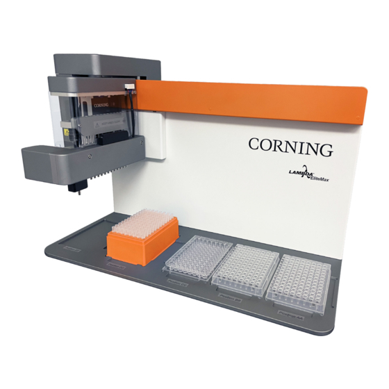
CORNING Lambda EliteMax Service Manual
Semi-automated benchtop pipettor
Hide thumbs
Also See for Lambda EliteMax:
- Quick start manual (5 pages) ,
- Instruction manual (44 pages) ,
- Frequently asked questions (2 pages)

Related Manuals for CORNING Lambda EliteMax


Summary of Contents for CORNING Lambda EliteMax
- Page 1 Lambda™ ® Corning EliteMax Semi-automated Benchtop Pipettor Service Manual Catalog Number: 6070 Corning Restricted...
-
Page 2: Table Of Contents
5.5 AC External Power Supply ......................27 5.6 Home Sensors ..........................27 5.7 Touch Screen Controller Pinout ....................28 5.8 Diagnostic and Error Codes ......................29 6.0 Liquid Head Maintenance ........................ 32 6.1 Seals Replacement ........................32 6.2 Pistons Replacement........................33 Corning Restricted... -
Page 3: Introduction
Corning Incorporated. Disclaimer The information in this document is subject to change without notice. Corning Incorporated reserves the right to revise this publication and to make changes from time to time in the content hereof without obligation of Corning Incorporated to notify any person of such revisions or changes. -
Page 4: Symbols And Conventions
In no event shall Corning Incorporated be liable or responsible for the use or integration of this product with other systems by its user, its subsidiaries or any other party. - Page 5 Pipettor should never be operated near water sources such as pools and water pipes. Never cover or obstruct the openings of the Corning Lambda EliteMax Semi-automated Benchtop Pipettor as they are designed for ventilation and prevention of the device’s interior from becoming too hot.
-
Page 6: Instrument Identification
1.4 Instrument Identification Corning Restricted... -
Page 7: Deck Positions And Orientation Convention
1.5 Deck Positions and Orientation Convention Corning Restricted... - Page 8 Typical landscape layout orientation. NOTE: Portrait adapter between plates. CAUTION: Before running any protocols, make sure ALL tip racks, plates, reservoirs, and accessories share the same orientation to avoid possible collision that can damage the instrument or the sample plate. Corning Restricted...
-
Page 9: Specifications
Precision shown as percentage of coefficient of variation. Multi-channel specifications represent the performance of all channels of a pipet. All values shown as reference. Corning FX tips used. See NOTE above. Technical Data Dimensions (W x D x H) Main Unit 20.5 x 11.3 x 14.2 in. -
Page 10: Initial Installation
AC wall power receptacle. The AC power receptacle should be able to supply approx. 300W and MUST be grounded to a true earth ground. 4. Power up the unit by rocking the Reset/Off switch located in the back of the Corning Lambda EliteMax Semi-automated Benchtop Pipettor to the Reset position. The instrument should boot up, and the home screen will appear in a few seconds. -
Page 11: Components Removal
2. Remove the screws (1), and carefully remove the acrylic cover (A). 3. Remove the screws (2), and dismount the liquid head (B) from the instrument. 2.2 Back Panel Removal 1. Remove the indicated screws. 2. Carefully separate the back cover (A) from the instrument. Corning Restricted... - Page 12 Corning Restricted...
-
Page 13: Front Panel Removal
1. Remove the back panel. 2. Remove the indicated screws (1). 3. Carefully separate the pulley cover (A). 4. Remove the screws (2) and nuts (3). 5. Carefully slide out the front panel (B) to remove it from the instrument. Corning Restricted... -
Page 14: Main Head Cover Removal
2.4 Main Head Cover Removal 1. Gently and slowly move the main head down. 2. Remove the indicated screws. 3. Carefully remove the main head cover (A). Corning Restricted... -
Page 15: Liquid Head Cover Removal
2.5 Liquid Head Cover Removal 1. Remove the liquid head (refer to section 2.1). 2. Remove the indicated screws. 3. Carefully remove the liquid head cover (A). Corning Restricted... -
Page 16: Power Entry Cover Removal
2.6 Power Entry Cover Removal 1. Remove the back and front panels. 2. Disconnect the associated wires and connectors from the main electronics board. 3. Remove the indicated screws. 4. Carefully remove the power entry cover (A). Corning Restricted... -
Page 17: Belts And Pulleys
2. If the idler pulleys (1) are replaced, remove the belt first by loosening the pulley screw nuts (2) and belt clamps screws (3). 3. After servicing the belt or the pulleys, adjust the belt tension and tighten the stepper motor screws. Corning Restricted... -
Page 18: Single-Head Axis
Use a small amount of lithium grease “Mobil Mobilux EP1” to lubricate the components (Mobil Mobilux EP1 is recommended, but a similar low viscosity lithium grease can be used as well). After assembly, make sure the idler pulley spins freely. Corning Restricted... - Page 19 Corning Restricted...
-
Page 20: Liquid Head Pistons Axis
3.5 Linear Guideways Lubrication Clean the rails and carriages before lubricating them. Use “Mobil Mobilux EP1” for lubrication. Apply a small amount of lubricant and remove any excess grease that can collect dust overtime. Corning Restricted... -
Page 21: Frame Alignment
“1-2-3 block”. 4. After alignment is completed, tighten the screws (1). NOTE: When rotating the assembly for adjustment, never exceed ±0.25 degree of rotation. After adjustment, check that the leadscrew rotates freely on complete stroke without binding. Corning Restricted... - Page 22 Corning Restricted...
-
Page 23: Main Axis Alignment
(A) until the tip barrels’ height is the same while the main head is moved across the axis over the “1-2-3 block”. 4. After alignment is completed, tighten all screws (1) on the linear rail (A). Corning Restricted... -
Page 24: Electrical System
Motor Motor Motor Motor Driver Driver Driver Driver Touch Screen Ground/Chassis Controller Main Head Board 5 Vdc Illumination LEDs Regulator Home Home Home Home Sensor Sensor Sensor Sensor Stepper Stepper Stepper Stepper Motor Motor Motor Motor Instrument Boundary Corning Restricted... -
Page 25: Motor Driver Board Pinout
5.2 Motor Driver Board Pinout Corning Restricted... -
Page 26: Main Head Board Pinout
5.3 Main Head Board Pinout 5.4 Power Entry Module Pinout Corning Restricted... -
Page 27: Ac External Power Supply
5.5 AC External Power Supply The Corning Lambda EliteMax Semi-automated Benchtop Pipettor uses a desktop style single-output power supply. This power supply is a class I power unit (with FG), equipped with a standard IE320-C14 AC inlet and adopting the input range from 85VAC to 264VAC. -
Page 28: Touch Screen Controller Pinout
5.7 Touch Screen Controller Pinout NOTE: Make sure that dip switches and On/Off switch are as indicated in the image. Corning Restricted... -
Page 29: Diagnostic And Error Codes
LEDs are solid green as shown in the image below. If there’s any error or alarm present in the motor driver, the touch screen controller will present it to the user, and the corresponding green LED will blink until the error is cleared. Corning Restricted... - Page 30 :xAL → where “x” represents the axis number in a range of 0 to 9. The queried motor driver axis will reply with the current alarm present. A value of 0 indicates that no alarms are present, otherwise see the table below for the alarm code information. Corning Restricted...
- Page 31 81 - 85 Limit switch was active when the command was received. uC failed to set '0' position during home command. 90 - 99 SPI communication errors with motor power drive. Corning Restricted...
-
Page 32: Liquid Head Maintenance
3. Remove all screws (1), and then remove the seal’s bar (C). 4. Clean and decontaminate the parts as needed. 5. Replace and lubricate all the seals (D) with Corning piston grease 15X3X (Corning Cat. No. 29021). 6. Reassemble in reverse order. -
Page 33: Pistons Replacement
4. Clean and decontaminate the parts as needed. 5. Reassemble the top bar with new pistons and c-clip and washers. 6. Apply a very thin coat of Corning piston grease 15X3X (Corning Cat. No. 29021) to the pistons ends. 7. Reassemble in reverse order. - Page 34 For additional product or technical information, visit www.corning.com/lifesciences or call 800.492.1110. Outside the United States, call +1.978.442.2200. For a listing of trademarks, visit www.corning.com/clstrademarks. All other trademarks are the property of their respective owners. © 2022 Corning Incorporated. All rights reserved. 3/22 CLS-AN-685...
Need help?
Do you have a question about the Lambda EliteMax and is the answer not in the manual?
Questions and answers