
Related Manuals for Corghi 2024 HP


Summary of Contents for Corghi 2024 HP
- Page 1 2024 HP Code 4-119730 - 10/2015 Italiano Manuale d’uso English Operator’s manual Français Manuel d’utilisation Deutsch Betriebsanleitung Español Manual de uso...
- Page 2 CORGHI Dear Purchaser Thank you for purchasing your Corghi Tyre Changer. Your Tyre Changer has been designed to provide years of safe and dependable service, as long as it is used and maintained in accordance with the instructions provided in this manual.
- Page 3 Reverse Drop Centre Wheels Mounting Standard Wheels Mounting of Stiff, Low Profile Tyres Reverse Drop Centre Wheels Proper Bead Lubrication for Mounting Protection Inflation Safety Precautions Lubrication and Removal of Valve Core Bead Sealing and Seating 2024 HP User Manual...
- Page 4 Individuals and Dates Trained _____________________________________________________________________ _____________________________________________________________________ _____________________________________________________________________ _____________________________________________________________________ _____________________________________________________________________ _____________________________________________________________________ _____________________________________________________________________ _____________________________________________________________________ _____________________________________________________________________ _____________________________________________________________________ 2024 HP User Manual...
-
Page 5: Table Of Contents
1.7 DURING USE ....................19 2. TRANSPORT, STORAGE AND HANDLING ........20 3. UNPACKING/ASSEMBLY ...............21 4. HOISTING/HANDLING ..............24 4.1 INSTALLATION CLEARANCES ..............24 5. 2024 HP DESCRIPTION..............25 6. OVERALL DIMENSIONS ...............27 7. EQUIPMENT COMPONENTS ............28 8. OPTIONAL ACCESSORIES ............30 9. BASIC PROCEDURES - USE ............31 9.1 PRELIMINARY CHECKS ................32... - Page 6 12. INFORMATION ABOUT SCRAPPING ..........50 13. ENVIRONMENTAL INFORMATION ..........50 14. INFORMATION AND WARNINGS CONCERNING HYDRAULIC FLUID ....................15. FIREFIGHTING MEANS USABLE ..........52 16. GLOSSARY ..................53 17. GENERAL ELECTRIC LAYOUT DIAGRAMS .......56 18. PNEUMATIC SYSTEM DIAGRAM ..........60 2024 HP User Manual...
-
Page 7: Getting Started
The first section provides the basic information to safely operate the 2024 HP tyre changer family. The following sections contain detailed information about equipment, procedures, and maintenance. -
Page 8: General Warning And Instructions
4. Never exceed the bead setting pressure provided by the tyre manufacturer, as stated on the sidewall of the tyre. Carefully monitor the gauge on the air hose. 5. If tires being mounted require more than the tire manufacturer’s maximum bead seating pres- 2024 HP User Manual... - Page 9 Cords rated for less current than the machine can overheat, resulting in a fire. • Care should be taken to arrange the cord so that it will not be tripped over or pulled. 2024 HP User Manual...
- Page 10 23. This machine may only be used, maintained or repaired by properly trained employees of your company. Repairs should only be performed by qualified personnel. Your CORGHI service representative is the most qualified person. The employer is responsible for determining if an employee is qualified to safely make any repairs to the machine should repair be attempted by users.
-
Page 11: Decal Placement
DECAL, MAX. INLET PRESSURE 16 BAR 446442 DECAL, WARNING UNDER PRESSURE TANK 450022 DECAL, FILTER 446598 DECAL, DISCONNECT POWER SUPPLY 432740 DECAL,EXPLOSION HAZARD 418135 DECAL, DIRECTION OF ROTA- TION 446433 DECAL, HAND CRUSHING HAZARD 446435 DECAL, HAND CRUSHING HAZARD 2024 HP User Manual... - Page 12 DECAL, INFLATING PEDAL 446437 DECAL, CONTROL HANDLE 446388 DECAL, CORRECT FEEDING NETWORK 446431 DECAL, HAND/FOOT CRUSHING HAZARD 446438 DECAL, TILTING BACK REGULATION 450005 POSTER, SAFETY INSTRUC- TIONS 4-100901 DECAL, 2-SPEED 425211 DECAL, ELECTRIC HAZARD 446436 DECAL, INFLATION VALVE 2024 HP User Manual...
- Page 13 Description DECAL, MODEL SERIAL NUM- 42015 - Correggio (RE) Italy Mod. ISO9001 QUAL. SYS. CERTIFIED ANNO DI COSTRUZIONE / Code MANUFACTURED X-XXXXXXXX/XX - XX Serial N. bar/psi XXXXXXXXX 426768 DECAL, PEDALS CONTROL 4-119732 DECAL, HIGH PERFORMANCE 2024 HP User Manual...
- Page 14 446442. EXPLOSION HAZARD. Do not puncture Danger - pressurised container. part nr 425211A. Risk of electrical shock. part nr 432740. Explosion hazard. part nr 450005. Safety instructions. Must be applied near the tire changer in a prominent position by the operator. 2024 HP User Manual...
-
Page 15: Electrical And Pneumatic Connections
• connect the machine to an industrial socket; the machine must not be connected to domestic sockets. 42015 - Correggio (RE) Italy Mod. ISO9001 QUAL. SYS. CERTIFIED ANNO DI COSTRUZIONE / Code MANUFACTURED X-XXXXXXXX/XX - XX Serial N. bar/psi XXXXXXXXX 2024 HP User Manual... - Page 16 DANGER Before making the electrical and pneumatic hook-ups, make sure that the machine is configured as described below: - pedals A and B (if present) in fully depressed position. - column C vertical (not tilted). 2024 HP User Manual...
-
Page 17: Technical Data
The permitted exposure levels may also vary according to the country. However, this information will enable machine users to make a more accurate assessment of hazards and risks. 2024 HP User Manual... -
Page 18: Air Pressures
This machine must be used only to remove and replace an automotive tyre on an au- tomotive rim, using the tools with which it is equipped. Any other use is improper and can result in an accident. The machine can not work on motorcycle wheels. 2024 HP User Manual... -
Page 19: Employee Training
Never allow any bystander to be within 20 feet of the machine during operation. To stop the machine in an emergency: • disconnect the power supply plug; • cut off the compressed air supply network by disconnecting the shut-off valve (snap coupling). 2024 HP User Manual... -
Page 20: Transport, Storage And Handling
(pallet) (Fig.3). Before moving the machine, refer to the HOISTING/ HANDLING section. NOTICE Keep the original packing in good conditions to be used if the equipment has to be shipped in the future. 2024 HP User Manual... -
Page 21: Unpacking/Assembly
- The machine comprises five main units (fig.4): 1 head 2 column guard 3 box with pressure gauge and standard equipment 4 air tank (TI version only) 5 body 2024 HP User Manual... - Page 22 - Nut T is to be screwed on to bead break cylinder pin V only when the machine is in- stalled and hooked up to the compressed air line. Tighten nut T until P is 3-4 mm. - Fit the side cover (Fig. 4a). 2024 HP User Manual...
- Page 23 2024 HP User Manual...
-
Page 24: Hoisting/Handling
IMPORTANT: for the correct and safe operation of the machine, the lighting level in the place of use should be at least 300 lux. CAUTION Do not install the machine outdoors. It is designed for use in an indoor, sheltered area. 2024 HP User Manual... - Page 25 Each time the machine remains disconnected from the pneumatic line for long periods, check the direct operation of the controls with the relative arm, following the pressure restoration procedure. Carry out the first control operation very slowly. 2024 HP User Manual...
-
Page 26: Hp Description
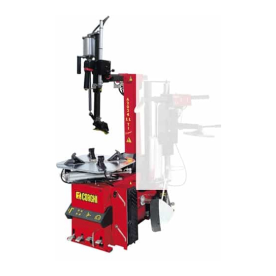
5. 2024 HP DESCRIPTION The 2024 HP is an electro-pneumatic tyre changer. The machine is compatible with any type of drop-centre single-piece rims with the dimensions and weights indicated in the paragraph TECHNICAL DATA. The sturdily constructed machine operates with the wheel in a vertical position for bead break- ing and in a horizontal position for mounting and demounting tyres. -
Page 27: Overall Dimensions
6. OVERALL DIMENSIONS (mm) Max. lenght A = 1090 mm Min. width B1 = 1270 mm Max. width B2 = 1700 mm Max. height H = 1835 mm 2024 HP User Manual... -
Page 28: Equipment Components
21 Doyfe inflator chuck (clips on to the tyre valve for inflation). 22 Inflation nozzles (air blast from nozzles expands tyre sidewalls to seal beads and allow inflation). 23 Air tank. 24 Lever (for locking the vertical side arm and the swing arm). 25 Blade protection. 2024 HP User Manual... - Page 29 2024 HP User Manual...
-
Page 30: Optional Accessories
(optional), consult the relevant operator and maintenance manual provided with the accessory documentation. 8. OPTIONAL ACCESSORIES For a complete list of optional accessories supplied on request, see the document “ORIGINAL ACCESSORIES FOR TIRE CHANGER” 2024 HP User Manual... -
Page 31: Basic Procedures - Use
- disconnect the power supply plug (Fig. 12a); - isolate the compressed air line by disconnecting the shutoff valve (quick-release connector) (Fig. 12b). WARNING Avoid unintended machine movement or failure. Use only original CORGHI tools and equipment. 2024 HP User Manual... -
Page 32: Preliminary Checks
(which is incorporated in the valve, fixed with the belt, glued inside the tyre, etc.) appropriate mount- ing/demounting procedures should be followed (ref. Approved mounting/demounting procedure for runflat and UHP tyres) 2024 HP User Manual... -
Page 33: Bead Breaking
- Position the wheel as shown in fig.16 and move the bead breaking shoe near the rim edge. 125 mm 45 mm 380 mm 300 mm EXTENDABLE ARM A Standard position B Large wheels position 125 mm 45 mm 380 mm 300 mm 2024 HP User Manual... -
Page 34: Clamping The Wheel
(Fig. 18a) to move the arms in “not working position” (all the way UP and BACK). - Press the button (Fig. 18b to lock the arms in this position. - Press pedal to tip the column back (Fig. 18c). 2024 HP User Manual... - Page 35 - Place the grippers in an open or closed position (fig.19). 10"-20" 13"-23" 14”-24” min 17'' 2024 HP User Manual...
-
Page 36: Demounting The Wheel
9.5. DEMOUNTING THE WHEEL - Release the lock button , releasing both the vertical and horizontals arm (fig 22a). - Press the button in middle position (Fig. 22b) to move the mounting/demounting device correctly against the rim edge (fig.23). 2024 HP User Manual... - Page 37 - Press the pedal to turn the table top clockwise. The upper bead will auto- matically be guided up and over the rim (fig.26). WARNING Avoid unintended lever movement and injury. Grip the lever firmly when using. 2024 HP User Manual...
-
Page 38: Mounting The Wheel
Press the turntable control pedal to turn the table clockwise and mount the bead. Use the drop centre by pressing the sidewall opposite the head to reduce tensional force on the bead as the wheel rotates (fig.28). 2024 HP User Manual... -
Page 39: Approved Uhp And Run Flat Tyre Demounting And Mounting
WDK (German Tyre Industry Association). 9.8. TYRE INFLATION 9.8.a. SAFETY INDICATIONS DANGER DANGER The use of inflation devices (e.g. guns) connected to power sources outside of the machine is not permitted. 2024 HP User Manual... - Page 40 4. Never place your head or any part of your body over a tyre during the inflation process or when attempting to seat beads. 2024 HP User Manual...
-
Page 41: Inflating Tyres
- Lower the vertical rod until it touches the rim (Fig. 31). - Lock the horizontal arm and the vertical rod (Fig. 31b) in this position. - Connect the Doyfe connector on the air hose to the valve stem (Fig. 31). 2024 HP User Manual... -
Page 42: Inflating Tubeless Tyres (Ti Versions Only)
Before carrying out the operations described below, always make sure that there is no dirt, dust or other impurities on the jaws near the air outlet holes. - Make sure that the wheel is secured to the table top with inside clamping Fig. 33). 2024 HP User Manual... - Page 43 Inflate the tyre by operating the proper pedal in inflation position (average) (Fig. 39) at short inter- vals; check the pressure gauge frequently to make sure that the pressure NEVER exceeds the maxi- mum pressure specified by the tyre manufacturer. 2024 HP User Manual...
- Page 44 Only activate the air inflation jets if the rim securing device is locked in place and the tire is properly clamped. WARNING ESPLOSION HAZARD. Never mount a tire to a rim that is not the same diameter (e.g., 16 1/2 inch tire mounting on a 16 inch rim). 2024 HP User Manual...
-
Page 45: Troubleshooting
Bead breaker cylinder lacks force, fails to break beads and leaks air Silencer plugged. ➥ Replace the silencer. Cylinder gaskets worn. ➥ Replace the gaskets. ➥ Replace the bead breaker cylinder. Bead breaker cylinder leaks air around the rod Air gaskets worn. ➥ Replace the gaskets. 2024 HP User Manual... - Page 46 When the column tilts back, the arm and vertical slide slip to their limit stops Defective clamping plate. ➥ Replace the plate. Clamping plate not adjusted. ➥ Adjust the plate. Vertical and horizontal limit stops do not operate 2024 HP User Manual...
- Page 47 The “Spare parts” handbook does not authorise the user to carry out any work on the machine other than the operations specifically described in the User Manual, and is only intended to enable the user to provide the technical assistance service with precise information in order to minimise response times. 2024 HP User Manual...
-
Page 48: Maintenance
NOTICE CORGHI declines all liability for claims deriving from the use of non-original spares or accessories. The purpose of the regulator filter unit plus lubricator (FRL) is to filter the air, adjust the pressure and lubricate it. - Page 49 Normally the cups do not need to be removed, but check if this is necessary for mainte- nance operations after a long period of use. If a manual operation is not sufficient, use the specific key provided (fig.40e). Clean with a dry cloth. Avoid contact with solvents. 2024 HP User Manual...
-
Page 50: Information About Scrapping
We also recommend you to adopt more measures for environment protection: recycling of the internal and external packaging of the product and proper disposal of used bat- 2024 HP User Manual... -
Page 51: Information And Warnings Concerning Hydraulic
- Inhalation: in case of exposure to strong concentration of vapours or mists, take the affected person out into the open air and then to Casualty. - Eyes: rinse with plenty of water and go to Casualty as soon as possible. - Skin: wash with soap and water. 2024 HP User Manual... -
Page 52: Firefighting Means Usable
YES* WARNING The indications given in this table are of a general nature and should be used as a general guide. All the applications of each type of extinguisher must be obtained from the relevant manufacturer. 2024 HP User Manual... -
Page 53: Glossary
The tread and sidewall work with different, inde- pendent rigidities, so during rolling, sidewall flexure is not transmitted to the tread. 4 - Side ring. This is a metal ring comprising several steel strands. The casing plys are secured to the side ring. 2024 HP User Manual... - Page 54 Tubeless tyres. Tubeless tyres consist of a tyre with inner sidewall lined with a thin layer of special impermeable rubber, called liner. This liner helps to maintain air pres- 2024 HP User Manual...
- Page 55 It is generally used for mounting low profile tyres. Air delivery regulator. Union allowing regulation of the air flow. Bead breaking. Operation that allows the tyre bead to be detached from the rim edge. 2024 HP User Manual...
-
Page 56: General Electric Layout Diagrams
17. GENERAL ELECTRIC LAYOUT DIAGRAMS 1Ph Tyre changer (Fig. 51) Power supply socket Inverter Motor Resistor Capacitor 2024 HP User Manual... - Page 57 100-115-200-230V DV Tyre changer (Fig. 52) Power supply socket Single / two-speed motor motor Motor Two-speed micro-switch Microswitch (CLOCKWISE rotation) Microswitch (ANTICLOCKWISE rotation) 2024 HP User Manual...
- Page 58 3Ph Tyre changer (Fig. 53) Power supply socket Inverter Motor 2024 HP User Manual...
- Page 59 3Ph 2-speed Tyre changer (Fig. 54) Power supply plug Double speed switch 3Ph. Motor Fuse 2024 HP User Manual...
-
Page 60: Pneumatic System Diagram
Column tilting cylinder Clamping handle valve Front clamping cylinder Rear clamping cylinder Column translation cylinder Swivel connector Delivery valve Tank Relief valve 5/2 NO Valve Tool actuator cylinder Air motor pump Air motor pump valve Inflation limiter unit 2024 HP User Manual... - Page 61 ELECTRIC MOTOR VERSION 2024 HP User Manual...
- Page 62 AIR MOTOR VERSION 2024 HP User Manual...
- Page 63 Note 2024 HP User Manual...
- Page 64 à la situation avant de poursuivre. Si vous avez des questions à propos du bon usage ou de l’entretien de votre démonte-pneu, veuillez téléphoner, à votre représentant agrée, de Corghi. Cordialement, Corghi SpA INFORMATION SUR LE PROPRIÉTAIRE...
- Page 65 Montage des pneus rigides et à profil bas Base creuse de la jante inversée Bonne lubrification du talon pour protéger le montage Gonflage Mesures de sécurité Lubrification et démontage de l’obus de valve Étanchéité et collage du talon 2024 HP Manuel d’utilisation...
- Page 66 Personnes formées et date de formation _____________________________________________________________________ _____________________________________________________________________ _____________________________________________________________________ _____________________________________________________________________ _____________________________________________________________________ _____________________________________________________________________ _____________________________________________________________________ _____________________________________________________________________ _____________________________________________________________________ _____________________________________________________________________ 2024 HP Manuel d’utilisation...
- Page 67 8. ACCESSOIRES EN OPTION ..............92 9. PROCÉDURES DE BASE - UTILISATION ...........93 9.1 VÉRIFICATION PRÉLIMINAIRE ................94 9.2 DÉCIDER DE QUEL CÔTÉ DE LA ROUE LE PNEU DOIT ÊTRE DÉMONTÉ . 94 9.3 DÉTALONNAGE ....................95 2024 HP Manuel d’utilisation...
- Page 68 13. ENVIRONMENTAL INFORMATION ..........112 14. INFORMATION ET AVERTISSEMENTS SUR LE FLUIDE HYDRAULIQUE ................15. MOYENS DE LUTTE CONTRE L’INCENDIE ......114 16. GLOSSAIRE .................. 114 17. SCHÉMA D’INTERCONNEXION ÉLECTRIQUE, GÉNÉRAL ... 118 18. SCHÉMA DU SYSTÈME PNEUMATIQUE ........122 2024 HP Manuel d’utilisation...
-
Page 69: Comment Démarrer
à Corghi le formulaire de changement de propriété joint à la page précédente de ce manuel. Autrement, le nouveau propriétaire peut envoyer un courriel à service@corghi.com. -
Page 70: Consignes Et Avertissement Général
4. Ne jamais dépasser la pression de collage du talon recommandé fourni par le fabricant de pneus, comme indiqué sur le flanc du pneu. Surveiller attentivement le manomètre du tuyau. 2024 HP Manuel d’utilisation... - Page 71 Ne pas faire fonctionner la machine avec un câble d’alimentation endommagé • Si une rallonge est nécessaire, utiliser un câble de puissance égale ou supérieure à celui de la machine. Un câble d’une valeur inférieure pourrait 2024 HP Manuel d’utilisation...
- Page 72 23. Cette machine peut être utilisée, entretenue ou réparée seulement par des employés formés de votre entreprise. Les réparations doivent être effectuées seulement par du personnel qualifié. Votre représentant du service CORGHI est la personne la plus qualifiée. L’employeur est responsable de déterminer si un employé...
-
Page 73: Emplacement De L'autocollant
AUTOCOLLANT, AVERTISSEMENT, RÉSERVOIR SOUS PRESSION 450022 AUTOCOLLANT, FILTRE 446598 AUTOCOLLANT, DÉCONNECTER L’ALIMENTATION 432740 AUTOCOLLANT, DANGER D’EXPLOSION 418135 AUTOCOLLANT, SENS DE LA ROTATION 446433 AUTOCOLLANT, RISQUE D’ÉCRASEMENT DE LA MAIN 446435 AUTOCOLLANT, RISQUE D’ÉCRASEMENT DE LA MAIN 2024 HP Manuel d’utilisation... - Page 74 446431 AUTOCOLLANT, RISQUE D’ÉCRASEMENT DE LA MAIN / DU PIED 446438 AUTOCOLLANT, RÈGLEMENT SUR LE BASCULEMENT VERS L’ARRIÈRE 450005 AUTOCOLLANT, CONSIGNES DE SÉCURITÉ 4-100901 AUTOCOLLANT, 2 VITESSES 425211 AUTOCOLLANT, DANGER D’ÉLECTROCUTION 446436 AUTOCOLLANT, VALVE DE GONFLAGE 2024 HP Manuel d’utilisation...
- Page 75 42015 - Correggio (RE) Italy NUMÉRO DE SÉRIE Mod. ISO9001 QUAL. SYS. CERTIFIED ANNO DI COSTRUZIONE / Code MANUFACTURED X-XXXXXXXX/XX - XX Serial N. bar/psi XXXXXXXXX 426768 AUTOCOLLANT, PÉDALES DE COMMANDES AUTOCOLLANT, HIGH PER- 4-119732 FORMANCE 2024 HP Manuel d’utilisation...
- Page 76 Ne pas perforer Danger - contenant pressurisé pièce no 425211 A. Risque d’électrocution. pièce no 432740. Danger d’explosion. pièce no 450005. Consignes de sécurité. Doit être apposé près du démonte-pneu dans un endroit bien visible par l’opérateur. 2024 HP Manuel d’utilisation...
-
Page 77: Connexions Électriques Et Pneumatiques
• brancher la machine à une prise industrielle; la machine ne doit pas être branchée à des prises domestiques. 42015 - Correggio (RE) Italy Mod. ISO9001 QUAL. SYS. CERTIFIED ANNO DI COSTRUZIONE / Code MANUFACTURED X-XXXXXXXX/XX - XX Serial N. bar/psi XXXXXXXXX 2024 HP Manuel d’utilisation... - Page 78 Avant d’effectuer les branchements électriques et pneumatiques, s’assurer que la machine est configurée comme décrite ci-dessous: - les pédales A et B (si disponible) sont en position complètement enfoncées. - la colonne C est en position verticale (et non pas inclinée). 2024 HP Manuel d’utilisation...
-
Page 79: Spécifications Techniques
Les niveaux d’exposition permis peuvent varier d’un pays à un autre. Cependant, cette information permettra aux utilisateurs de la machine de mieux évaluer les dangers et les risques. 2024 HP Manuel d’utilisation... -
Page 80: Pression D'air
Cette machine doit être utilisée uniquement pour enlever et remplacer un pneu d’automobile sur une jante d’automobile, à l’aide d’outils avec lesquels il est équipé. Tout autre usage est inapproprié et pourrait provoquer un accident. Cette machine ne fonctionne pas sur les roues de motos. 2024 HP Manuel d’utilisation... -
Page 81: Formation Des Employés
Pas d’observateur à 20 pi de la machine durant son fonctionnement. Pour arrêter la machine en cas d’urgence : • débrancher la prise d’alimentation électrique; • couper le réseau d’alimentation de l’air comprimé en débranchant la vanne d’arrêt (raccord à enclenchement rapide). 2024 HP Manuel d’utilisation... -
Page 82: Transport, Entreposage Et Manutention
élévateur dans les trous prévus à cet effet à la base de l’emballage (palette) (Fig.3). Avant de déplacer la machine, veuillez consulter la section LEVAGE / MANUTENTION. AVIS Conserver l’emballage original en bon état pour utilisation future si l’équipement doit être expédié. 2024 HP Manuel d’utilisation... -
Page 83: Déballage / Montage
- La machine est composée de cinq principaux blocs (Fig.4): 1 tour 2 protection de la colonne 3 boîte avec un manomètre et de l’équipement standard 4 réservoir d’air (pour le modèle TI seulement) 5 bâti 2024 HP Manuel d’utilisation... - Page 84 - L’écrou T doit être vissé sur la goupille V du cylindre du détalonneur uniquement lorsque la machine est installé et branché à la conduite d’air comprimé. Serrer les écrous T jusqu’à ce que P soit à 3 - 4 mm. - Monter le panneau de côté (Fig. 4a). 2024 HP Manuel d’utilisation...
- Page 85 2024 HP Manuel d’utilisation...
-
Page 86: Levage / Manutention
IMPORTANT : pour le bon fonctionnement et la sécurité de la machine, le niveau d’éclairage dans le lieu d’utilisation devrait être d’au moins 300 lux. MISE EN GARDE Ne pas installer la machine à l’extérieur. Elle est conçue pour une utilisation à l’intérieure dans un endroit couvert. 2024 HP Manuel d’utilisation... - Page 87 Chaque fois que la machine reste débranchée de la conduite d’air pour de longues périodes de temps, vérifier le fonctionnement direct des commandes avec le bras déport, suite à la procédure de restauration de la pression. Faire la première opération de contrôle très lentement. 2024 HP Manuel d’utilisation...
-
Page 88: A 9220 Ti Description
5. 2024 HP DESCRIPTION Le 2024 HP est un démonte-pneu électro-pneumatique. La machine est compatible avec tout type de jantes monobloc à base creuse avec les dimensions et poids indiqués dans le paragraphe des SPÉCIFICATIONS TECHNIQUES. La machine construite solidement fonctionne avec une roue en position verticale pour le détalonnage et en position horizontale pour le montage et le démontage des pneus. -
Page 89: Dimensions Hors Tout
6. DIMENSIONS HORS TOUT (mm) Longueur max A = 1090 mm Largeur min B1 = 1270 mm Largeur max B2 = 1700 mm Hauteur max H = 1835 mm 2024 HP Manuel d’utilisation... -
Page 90: Composantes De L'équipement
22 Buses de gonflage (le jet d’air des buses élargit les flancs des pneus aux talons et permet le gonflement). 23 Réservoir à air. 24 Levier (pour verrouiller le bras vertical de côté et le bras oscillant). 25 Protège-lame. 2024 HP Manuel d’utilisation... - Page 91 2024 HP Manuel d’utilisation...
-
Page 92: Accessoires En Option
(en option), consulter l’opérateur concerné, le manuel d’entretien fourni avec la documentation de l’accessoire. 8. ACCESSOIRES EN OPTION Pour une liste complète d’accessoires au choix fournis sur demande, voir le document « ACCESSOIRES ORIGINALES POUR LE DÉMONTE-PNEU » 2024 HP Manuel d’utilisation... -
Page 93: Procédures De Base - Utilisation
- isoler la conduite d’air comprimé en débranchement la vanne d’arrêt (raccord à connexion rapide) (Fig. 12b). AVERTISSEMENT Éviter tout mouvement imprévu de la machine ou toute chute. Utiliser seulement les outils et l’équipement d’origine de CORGHI. 2024 HP Manuel d’utilisation... -
Page 94: Vérification Préliminaire
(qui est incorporé dans la valve, fixé à la ceinture, collé à l’intérieur du pneu, etc.) il faut suivre correctement les procédures de montage et démontage (réf. Procédures approuvées pour montage /démontage de pneus pour roulage à plat et des pneus UHP) 2024 HP Manuel d’utilisation... -
Page 95: Détalonnage
125 mm 45 mm 380 mm 300 mm BRAS EXTENSIBLE A Position standard B Position des roues larges 125 mm 45 mm 380 mm 300 mm 2024 HP Manuel d’utilisation... -
Page 96: Blocage De La Roue
(vers le HAUT et le BAS). - Appuyer sur le bouton (Fig. 18b pour ver- rouiller les bras dans cette position. - Appuyer sur la pédale pour incliner la colonne à nouveau (Fig. 18c). 2024 HP Manuel d’utilisation... - Page 97 - Placer les mors en position ouvert ou fermé (Fig.19). 10"-20" 13"-23" 14”-24” min 17'' 2024 HP Manuel d’utilisation...
-
Page 98: Démontage De La Roue
- Relâcher le bouton de déverrouillage qui relâchera le bras vertical et horizontal (Fig.22a). - Appuyer sur le bouton à la position du milieu (Fig. 22b) pour déplacer dispositif montage démontage correctement contre le rebord de la jante (Fig.23) 2024 HP Manuel d’utilisation... - Page 99 (Fig.26). AVERTISSEMENT Éviter tout mouvement imprévu du levier et toute blessure. Tenir le levier fermement lors de l’utilisation. 2024 HP Manuel d’utilisation...
-
Page 100: Montage De La Roue
Utiliser la base creuse de la jante en le poussant vers le bas sur la paroi laté- rale opposée à la tête (Fig.28) pour réduire la force de tension sur le bourrelet lors de la rotation de la roue. 2024 HP Manuel d’utilisation... -
Page 101: Un Pneu Pour Roulage À Plat
Ne jamais dépareiller la taille de la roue et de la jante. • Éviter les blessures corporelles ou mortelles DANGER L’utilisation des appareils de gonflage branchés à des sources externes (par ex. : pistolets) est interdite. 2024 HP Manuel d’utilisation... - Page 102 4. Ne jamais exposer votre tête ou toute autre partie du corps au-dessus d’un pneu pendant le gonflage ou le collage du talon. 2024 HP Manuel d’utilisation...
-
Page 103: Gonflage Des Pneus
(Fig. 31). - Verrouiller le bras vertical et la tige verticale (Fig. 31b) dans cette position. - Brancher le connecteur Doyfe au flexible de gonflage au corps de valve (Fig. 31). 2024 HP Manuel d’utilisation... -
Page 104: Gonflage Des Pneus À Chambre Incorporée (Seulement Les Modèles Ti)
Avant d’effectuer les opérations décrites ci-dessous, toujours s’assurer qu’il n’y a pas de saleté, de poussière ou d’autres impuretés sur les mâchoires près des trous de sortie d’air. - S’assurer que la roue est fixée au plateau avec les mors à l’intérieur (Fig. 33). 2024 HP Manuel d’utilisation... - Page 105 Gonfler le pneu en utilisant la bonne pédale dans la position de gonflement (moyen) (Fig. 39) par à coup; vérifier le manomètre fréquemment pour s’assurer que la pression ne dépasse JAMAIS la pression maximale indiquée par le fabricant de pneus. 2024 HP Manuel d’utilisation...
- Page 106 AVERTISSEMENT DANGER D’EXPLOSION. Ne jamais monter un pneu sur une jante qui n’est pas du même diamètre (par exemple, pneu de 16,5 po monté sur une jante de 16 po). 2024 HP Manuel d’utilisation...
-
Page 107: Dépannage
à des fuites d’air Silencieux bouché. ➥ Remplacer le silencieux. Joints du cylindre usés. ➥ Remplacer les joints. ➥ Remplacer le cylindre du détalonneur. Fuite d’air sur le cylindre du détalonneur autour de la tige. 2024 HP Manuel d’utilisation... - Page 108 Lorsque la colonne s’incline vers l’arrière, le bras et la fente verticale glissent jusqu’à leurs butées de fin de course. Plateau de blocage défectueux. ➥ Remplacer le plateau. Plateau de blocage déréglé. ➥ Régler le plateau. 2024 HP Manuel d’utilisation...
- Page 109 à permettre à l’utilisateur de fournir le service d’assistance technique avec des informations précises afin de minimiser les temps de réponse. 2024 HP Manuel d’utilisation...
-
Page 110: Information Sur Les Rebuts
AVIS CORGHI décline toute responsabilité pour les réclamations découlant de l’utilisation de pièces de rechange ou d’accessoires, qui ne sont pas d’origine. Le groupe filtre régulateur plus graisseur « FRL » a pour fonction de filtrer l’air, régler sa pression et le lubrifier. - Page 111 Normalement on ne doit pas démonter les bacs, mais au besoin, pour des opérations d’entretien, après de longues périodes d’utilisation. Si une opération manuelle n’est pas suffisante, se servir de la clé fournie (Fig.40e). Nettoyer avec un chiffon sec. Éviter le contact avec des solvants. 2024 HP Manuel d’utilisation...
-
Page 112: Information Sur L'environnement
Dans cette optique, les fabricants et les distributeurs d’appareils électriques et électroniques organisent des systèmes de récolte et de traitement desdits appareils. Au terme de la vie de votre produit, adressez-vous à votre distributeur qui vous fournira tout renseignement sur les modalités de collecte. 2024 HP Manuel d’utilisation... -
Page 113: Information Et Avertissements Sur Le Fluide Hydraulique
- Utiliser les équipements de prévention et de protection suivants : • gants résistant aux huiles minérales avec doublure en peluche ; • lunettes de protection, en cas de projections ; • tabliers résistants aux huiles minérale ; • boucliers de protection, en cas de projections. 2024 HP Manuel d’utilisation... -
Page 114: Moyens De Lutte Contre L'incendie
Le pneu est la partie principale de la roue, en contact avec la route, conçu pour retenir une pression d’air interne et à résister à toutes les autres contraintes découlant de l’utilisation. Une section du pneu montre les diverses parties dont il se compose : 2024 HP Manuel d’utilisation... - Page 115 Il s’agit d’un marquage qui indique la circonférence de la partie supérieure du talon et est utilisé comme référence pour vérifier le centrage exact du pneu sur la jante après montage. Zone basse. Il s’agit d’un marquage circonférentiel dans 2024 HP Manuel d’utilisation...
- Page 116 Ce type de pneu doit être monté sur une jante spécifique, sur laquelle la valve est directement fixée. II - Jante (Roue). La roue est la partie métallique rigide qui relie les moyeux du véhicule aux pneus, sur une base fixe, 2024 HP Manuel d’utilisation...
- Page 117 à profil bas. Dispositif de réglage de débit d’air. Raccord permettant de réguler le débit d’air. Détalonnage. Opération qui permet de détacher le talon du pneu du rebord de la jante. 2024 HP Manuel d’utilisation...
-
Page 118: Schéma D'interconnexion Électrique, Général
17. SCHÉMA D’INTERCONNEXION ÉLECTRIQUE, GÉNÉRAL Démonte-pneu à 1 phase (Fig.51) Prise d’alimentation Inverseur Moteur Résistance Condensateur 2024 HP Manuel d’utilisation... - Page 119 Démonte-pneu 100-115-200-230 V démonte-pneu DV (Fig. 52) Prise d’alimentation Moteur à un / deux vitesses Moteur Microrupteur deux vitesses Microrupteur (rotation SENS HORAIRE) Microrupteur (rotation SENS ANTIHORAIRE) 2024 HP Manuel d’utilisation...
- Page 120 Démonte-pneu à 3 phases (Fig. 53) Prise d’alimentation Inverseur Moteur 2024 HP Manuel d’utilisation...
- Page 121 Démonte-pneu à 3 phases, 2 vitesses (Fig. 54) Prise d’alimentation Interrupteur à double contact 3 phases. Moteur Fusible 2024 HP Manuel d’utilisation...
-
Page 122: Schéma Du Système Pneumatique
Connecteur pivotant Soupape de refoulement Réservoir Valve de sûreté 5/2 PAS de valve Outil vérin de commande Moteur de la pompe à air Soupape du moteur de la pompe à air Unité pour limiter le gonflage 2024 HP Manuel d’utilisation... - Page 123 DÉMONTE-PNEU À MOTEUR ÉLECTRIQUE 2024 HP Manuel d’utilisation...
- Page 124 DÉMONTE-PNEU À MOTEUR PNEUMATIQUE 2024 HP Manuel d’utilisation...
- Page 125 Note Remarques 2024 HP Manuel d’utilisation...
- Page 126 CORGHI S.p.A. - Strada Statale 468 No. 9 42015 CORREGGIO - RE - ITALY Phone. +39 0522 639.111 - Fax +39 0522 639.150 www.corghi.com - info@corghi.com...
Need help?
Do you have a question about the 2024 HP and is the answer not in the manual?
Questions and answers