Table of Contents

Subscribe to Our Youtube Channel
Related Manuals for Wood-mizer LT70DC


Summary of Contents for Wood-mizer LT70DC
- Page 1 Wood-Mizer ® Remote Operation Wireless Option rev. A3.00 Operator’s Manual Safety is our #1 concern! Read and understand all safety information and instructions before operating, setting up or maintaining this machine. July 2007 Form #120...
-
Page 2: Table Of Contents
Table of Contents Section-Page SECTION 1 REMOTE OPERATION Safety Precautions ..................... 1-1 Control Panel Overview .................... 1-2 Remote Operation...................... 1-5 SECTION 2 DIAGNOSTICS AND MAINTENANCE Diagnostics - Transmitter ..................2-1 Diagnostics - Receiver....................2-3 Maintenance ......................2-4 Daily Maintenance Procedures Three-Month Maintenance Procedures Six-Month Maintenance Procedures SECTION 3... -
Page 3: Remote Operation
WARNING! Failure to follow the SAFETY PRECAUTIONS may result in radio equipment failure or serious personal injury. CAUTION! Wood-Mizer will not bear responsibility for any unapproved changes or modifications made to the equipment. Installation CAUTION! PROVIDE A SAFETY CUTOFF SWITCH. -
Page 4: Control Panel Overview
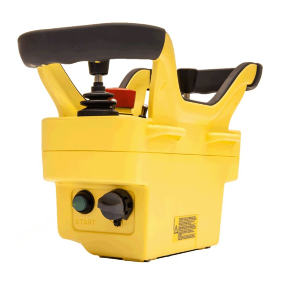
Control Panel Overview LT70DC sawmills can be equipped with the saw head remote control system (with a wireless control panel). This system allows you to fully control the saw head, i.e. engage and disengage the blade, the power feed and up/down operation, the blade guide arm and the debarker as well as to adjust the feed rate. - Page 5 Remote Operation Control Panel Overview See Figure 1-1. Wireless control panel functions Saw Head Forward Blade Guide In/Out Blade Drive On/Off Saw Head Backward Saw Head Up Debarker On/Off Saw Head Down Emergency Stop Button Feed Rate Dial Battery Charge Indicator (Red) Debarker In/Out Panel Working Status...
- Page 6 Remote Operation Control Panel Overview See Figure 1-2. Wireless control panel functions (side panel) START Pushbutton Air-KEY (Electronic Starting Key) ROdoc042915 Remote Operation...
- Page 7 Remote Operation Remote Operation Remote Operation Set up the sawmill as instructed in your sawmill operator’s manual. Install the charged battery. Refer to the provided Wireless System manufacturer’s manual for detailed instructions for installing and charging the battery. NOTE: When the battery is fully charged, the panel should run for approximately 20 hours at 20 To turn on the wireless control panel on any DC sawmill: Make sure that all switches and joysticks are in the neutral or OFF position.
- Page 8 Remote Operation Remote Operation Insert the electronic starting key (Air-KEY) into the corresponding socket located on the left side of the control panel. Turn the key right to the ”1” position. Push and hold the START button on the left side of the control panel until the panel ...
- Page 9 Remote Operation Remote Operation NOTE: The electronic starting key (Air-KEY) stores the receiver identification data. transmitter cannot communicate with the receiver without this key. Do not lose the Air-KEY. Remote Operation ROdoc042915...
- Page 10 Remote Operation Remote Operation ROdoc042915 Remote Operation...
-
Page 11: Diagnostics And Maintenance
DIAGNOSTICS AND MAINTENANCE Diagnostics - Transmitter SECTION 2 DIAGNOSTICS AND MAINTENANCE IMPORTANT! The description of the Wireless System diagnostics and maintenance procedures provided below is a supplement to the equipment manufacturer’s manual. Before maintaining the Wireless System performing diagnostics, read equipment manufacturer’s manual. - Page 12 DIAGNOSTICS AND MAINTENANCE Diagnostics - Transmitter The LED blinks fast. The transmitter and receiver communicate. It is possible to start the radio remote control by pressing the START pushbutton. The LED blinks It is possible to send commands. slowly (one blink per second).
-
Page 13: Diagnostics - Receiver
DIAGNOSTICS AND MAINTENANCE Diagnostics - Receiver Diagnostics - Receiver See Figure 2-2. Signal Lights ENABLE LED POWER LED Signal Signal Light Possible Reason Color The light is off. POWER The receiving unit is not powered. Light The light is on. POWER The receiving unit is powered. -
Page 14: Maintenance
DIAGNOSTICS AND MAINTENANCE Maintenance Maintenance 2.3.1 Daily Maintenance Procedures Before starting to work: Make sure that the symbols of all control elements on the transmitter panel are readable. Replace the transmitter panel if necessary. Check that the three plates on the transmitting unit are intact and readable. ... -
Page 15: Six-Month Maintenance Procedures
contact closes when the corresponding function is activated and opens when the function is disabled. If any transmitter/receiver fault occurs, contact your Wood-Mizer Representative. All repairs of the equipment should be done by authorized persons only. DIAGNOSTICS AND MAINTENANCE... -
Page 16: Specifications
Specifications SECTION 3 SPECIFICATIONS Receiver Transmitter Size 287mm x 185mm x 105mm 258mm x 170mm x 126mm Weight 2.2 kg 1.3 kg (w/battery) Construction High impact plastic, waterproof (IP65) High impact plastic, waterproof Input Power 12V-24V DC 7.2V DC 1.2 A Battery Life ca. -
Page 17: Parts List
+48-63-2626000. From the continental U.S., call our toll-free Parts hotline at 1-800-448-7881. Have your customer number, vehicle identification number, and part numbers ready when you call. From other international locations, contact the Wood-Mizer distributor in your area for parts. Parts List doc042915... -
Page 18: Wireless Control Kit, Dc Sawmills
Parts List Wireless Control Kit, DC Sawmills Wireless Control Kit, DC Sawmills REF. DESCRIPTION ( Indicates Parts Available In Assemblies Only) PART # QTY. WIRELESS CONTROL SYSTEM, DC SAWMILLS 097803 BRACKET, WIRELESS JUNCTION BOX 096930-1 INTERFACE, AUTEC DC - COMPLETE 515304 INTERFACE, AUTEC DC 516174... -
Page 19: Control Hanger, Ac Wireless (Les)
Parts List CONTROL HANGER, AC WIRELESS (LES) CONTROL HANGER, AC WIRELESS (LES) REF. DESCRIPTION ( Indicates Parts Available In Assemblies Only) W-M PART # QTY. HANGER, AC WIRELESS CONTROL 501440-1 HANGER WELDMENT, CONTROL 100458-1 BLOCK, BORAMID 100222 SCREW, M4X16 5.8-B CROSS RECESSED PAN HEAD F81011-42 MAGNET, ORANGE-PAINTED S10519-1... -
Page 20: Control Hanger, Ac Wireless (Lt40/70)
Parts List CONTROL HANGER, AC WIRELESS (LT40/70) CONTROL HANGER, AC WIRELESS (LT40/70) REF. DESCRIPTION ( Indicates Parts Available In Assemblies Only) W-M PART # QTY. HANGER, AC WIRELESS CONTROL 100451 HANGER WELDMENT, CONTROL 100458-1 BLOCK, BORAMID 100222 SCREW, M4X16 5.8-B CROSS RECESSED PAN HEAD F81011-42 MAGNET, ORANGE-PAINTED S10519-1... -
Page 21: Wireless Control Kit, Lt20 Ac
Parts List WIRELESS CONTROL KIT, LT20 AC WIRELESS CONTROL KIT, LT20 AC REF. DESCRIPTION ( Indicates Parts Available In Assemblies Only) W-M PART# QTY. LT20 AC WIRELESS CONTROL SYSTEM 504354 HANGER, LT20 AC WIRELESS CONTROL 100200 HANGER, AC WIRELESS CONTROL 501440-1 BOLT M8X16-8.8, SOCKET HEAD F81002-39... - Page 22 Parts List WIRELESS CONTROL KIT, LT20 AC WASHER, 8.4 FLAT ZINC F81054-1 BOLT, M12X140-8.8 HEX HEAD ZINC F81004-35 WASHER, 13 FLAT ZINC F81056-1 doc042915 Parts List...
Need help?
Do you have a question about the LT70DC and is the answer not in the manual?
Questions and answers