Wood-mizer LT40 Safety, Setup, Operation & Maintenance Manual
Hide thumbs
Also See for LT40:
- User manual (146 pages) ,
- Safety, setup, operation & maintenance manual (191 pages) ,
- Safety, operation, maintenance & parts manual (45 pages)
Table of Contents
Advertisement
Quick Links
Wood-Mizer
Safety, Setup, Operation
& Maintenance Manual
LT30 / LT30 Super
LT40 / LT40 Super
Safety is our #1 concern! Read and understand all safety
information and instructions before operating, setting up or
maintaining this machine.
October 2004
®
Sawmill
rev. F4 - F6.01
rev. F5 - F7.01
Form #686
Advertisement
Table of Contents
Troubleshooting

Subscribe to Our Youtube Channel
Related Manuals for Wood-mizer LT40


Summary of Contents for Wood-mizer LT40
- Page 1 Safety, Setup, Operation & Maintenance Manual LT30 / LT30 Super rev. F4 - F6.01 LT40 / LT40 Super rev. F5 - F7.01 Safety is our #1 concern! Read and understand all safety information and instructions before operating, setting up or maintaining this machine.
- Page 2 If You Need To Order Parts... From the continental U.S., call our toll-free Parts hotline at 1-800-525-8100. Please have the vehicle identification number and your customer number ready when you call. Wood-Mizer will accept these methods of payment: Visa, Mastercard, or Select Purchase Prepayment Net 15 (with approved credit) Be aware that shipping and handling charges may apply.
- Page 3 Take notice of all safety warnings throughout this manual and those posted on the machine. Keep this manual with this machine at all times, regardless of ownership. ® *Wood-Mizer is a registered trademark of Wood-Mizer Products, Inc. 3096doc041610iii...
- Page 4 Customer No: ___________________ Model No: The vehicle identification number locations for mills LT30 rev. F4773, LT30 Super rev. F8009, LT40 rev. F5673, and LT40 Super rev. F8002 and later are shown in the following figure. V.I.N. LOCATIONS FOR LATER MODEL MILLS.
- Page 5 The vehicle identification number locations for mills prior to LT30 rev. F4773, LT30 Super rev. F8009, LT40 rev. F5673, and LT40 Super rev. F8002 are shown in the following fig- ure. V.I.N. LOCATIONS FOR EARLIER MODEL MILLS. 3096doc041610v...
- Page 6 V.I.N. DESCRIPTION. NOTE: Sawmills manufactured before January, 1997 do not have the repeated revision level or the minor revision level. MODEL NUMBER DESCRIPTION. 3096doc041610...
-
Page 7: Table Of Contents
Table of Contents Section-Page SECTION 1 SAFETY & GENERAL INFORMATION Blade Handling......................1-1 Sawmill Setup......................1-2 Sawmill Operation..................... 1-3 Electric Sawmill ......................1-5 Belt Sizes ........................1-9 Blade Sizes ......................1-10 Cutting Capacity...................... 1-11 Engine/Motor Specifications ................... 1-12 Overall Dimensions ....................1-13 1.10 Components...................... - Page 8 Table of Contents Section-Page SECTION 3 MAINTENANCE Wear Life........................3-1 Blade Guides ......................3-2 Blade Housing ......................3-3 Carriage Track, Wiper & Scrapers ................3-4 Vertical Mast Rails ....................3-5 Drum Switches ......................3-6 Miscellaneous Lubrication ..................3-7 Blade Tensioner......................3-8 Blade Wheel Belts .....................
- Page 9 Table of Contents Section-Page SECTION 5 SAWMILL ALIGNMENT Pre-Alignment Procedures..................5-1 Frame Setup....................... 5-2 Blade Installation And Alignment................5-3 Saw Head Slide Pad Adjustment................5-5 Adjusting The Lower Track Rollers................5-7 Adjusting Bed Rails To The Blade................5-9 Blade Guide Arm Vertical Adjustment ..............5-12 Blade Guide Arm Horizontal Adjustment...............
- Page 10 Table of Contents Section-Page 3096doc041610 Table of Contents...
-
Page 11: Safety & General Information
Safety & General Information Blade Handling SECTION 1 SAFETY & GENERAL INFORMATION This symbol calls your attention to instructions concerning your personal safety. Be sure to observe and follow these instructions. This symbol accompanies a signal word. The word DANGER refers to hazards that can cause death or serious, irreversible personal injury. -
Page 12: Sawmill Setup
Safety & General Information Sawmill Setup Sawmill Setup WARNING! Put front outrigger down before moving cutting head from the rest position. Failure to do so may result in serious injury. WARNING! Do not set up the mill on ground with more than a 10 degree incline. -
Page 13: Sawmill Operation
Safety & General Information Sawmill Operation Sawmill Operation DANGER! Never operate or tow the sawmill without all guards and covers in place and secured. Be sure the blade housing and pulley covers are in place and secure. Use the safety retainer pin and cable to fasten blade housing covers. - Page 14 Wood-Mizer sawmill. All Wood-Mizer mill owners are encouraged to become thoroughly familiar with these applicable laws and comply with them fully while using or towing the mill.
-
Page 15: Electric Sawmill
Safety & General Information Electric Sawmill Electric Sawmill USE PROPER PROCEDURE WHEN CONDUCTING ELECTRICAL SAFETY CHECKS AND MAINTENANCE DANGER! Make sure all electrical installation, service and/or maintenance work is performed by a qualified electrician and is in accordance with applicable electrical codes. DANGER! Hazardous voltage inside the electric sawmill discon- nect box, starter box, and at the motor can cause shock, burns, or... - Page 16 Safety & General Information Electric Sawmill DANGER! Lockout procedures must be used during: Changing or adjusting blades Unjamming operations Cleaning Mechanical repair Electrical maintenance Retrieval of tools/parts from work area Activities where guards or electrical panel guard is open or removed Maintenance hazards include: Blade contact...
- Page 17 Safety & General Information Electric Sawmill SAWMILL LOCKOUT PROCEDURE Lockout procedures must be followed (see ANSI Standard Z244.1-1982 and OSHA regu- lation 1910.147). Purpose: This procedure establishes the minimum requirements for lockout of energy sources that could cause injury. Responsibility: The responsibility for seeing that this procedure is followed is binding upon all workers.
- Page 18 Owner’s Responsibility The procedures listed in this manual may not include all ANSI, OSHA, or locally required safety procedures. It is the owner/operator’s responsibility and not Wood-Mizer Products to ensure all operators are properly trained and informed of all safety protocols.
-
Page 19: Belt Sizes
TABLE 1-1 For LT30 Rev. F6+ and LT40 Rev. F7+. For LT30 Rev. F4 - F5 and LT40 Rev. F5 - F6. 036163 Kevlar 2BXF71 belt replaces P12949 2BX71 belt supplied prior to 9/03. Kevlar belt reduces stretch and provides great- er range of adjustment. -
Page 20: Blade Sizes
Blade Sizes See Table 1-2. Wood-Mizer TRU•SHARP™ offers three types of blades to provide effi- cient sawing for all models of sawmills. The engine/motor size of your sawmill and the type of wood you saw should determine which blade you choose for optimum perfor- mance. -
Page 21: Cutting Capacity
Safety & General Information Cutting Capacity Cutting Capacity See Table 1-3. The log size capacities of the LT30, LT40, LT30 Super, and LT40 Super sawmills are listed below. Max. Max. Diameter Length LT30/LT30 Super 36" (91.5 cm) 16' 8" (5.1 m) LT40/LT40 Super 36"... -
Page 22: Engine/Motor Specifications
Safety & General Information Engine/Motor Specifications Engine/Motor Specifications See Table 1-5. The power options available for the LT30, LT40, LT30 Super, and LT40 Super sawmills are listed below. Engine/Motor Type Manufacturer Model Number 18HP Gasoline Onan P218G-I 24HP Gasoline Onan... -
Page 23: Overall Dimensions
Safety & General Information Overall Dimensions Overall Dimensions See Table 1-6. The overall dimensions of the LT30, LT40, LT30 Super, and LT40 Super sawmills are listed below. Model Length Width Height Weight LT30 19’ 11" (5.3 m) 6’ 2 1/2" (1.9 m) 7’ 6" (2.3 m) 1858 lbs. -
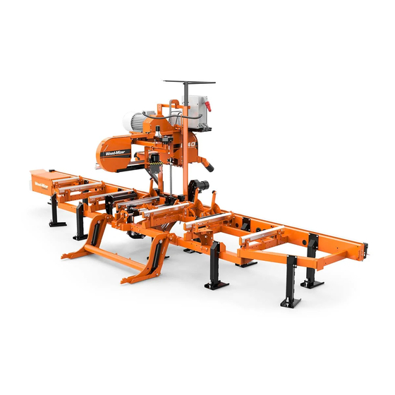
Page 24: Components
Safety & General Information Components 1.10 Components See Figure 1-1. The major components of the Wood-Mizer LT30, LT40, LT30 Super, and LT40 Super are shown below. Engine/Drive Assembly Water Lube Cutting Head Outer Blade Guide Arm Clutch/Brake Handle Blade Side Support... -
Page 25: Setup & Operation Stationary Sawmill Setup
LT30 Stationary Sawmill 300072 LT40 Stationary Sawmill FIG. 2-1 NOTE: Make sure the unit is level before securing. It IS possible to twist the mill frame by jacking one foot higher than the others. - Page 26 Setup & Operation Stationary Sawmill Setup DANGER! Do not operate a stationary sawmill without the feet securely fastened to the floor. If the feet are not securely fastened, loading and turning large logs could cause the sawmill to tip over. 3.
-
Page 27: Portable Sawmill Setup
Setup & Operation Portable Sawmill Setup Portable Sawmill Setup WARNING! Do not set up the mill on ground with more than a 10 degree incline. If setup on an incline is necessary, put blocks under one side of the mill or dig out areas for outrig- ger legs to keep mill level. - Page 28 Setup & Operation Portable Sawmill Setup 1. Unhitch the mill from the vehicle. See Figure 2-3. FIG. 2-3 2. Lower and set the front three outriggers. Lift the weight from the locking pin using the jack handle. Pull the locking pin to release the outrigger and lower the outrigger as necessary. Secure with the locking pin.
- Page 29 Setup & Operation Portable Sawmill Setup Provided Adjustment Wrench Height Adjustment Nut Existing Outrigger Guide Locking Pin FAO Base SM0213 FIG. 2-3. BASE HEIGHT ADJUSTMENT (FOR FINE ADJUST OUTRIGGER ONLY). 3. Unhook the carriage safety chain, located at the bottom of the vertical mast, near the bat- tery box.
- Page 30 Setup & Operation Portable Sawmill Setup rigger and use the locking pin to secure in position. CAUTION! Do not adjust the FAO outrigger base height while there is weight on the FAO. Damage to the FAO may result. 8. Remove the fenders by lifting them out of the slots. CAUTION! To prevent fender damage, remove fenders before operating sawmill or loading logs.
-
Page 31: Replacing The Blade
Setup & Operation Replacing The Blade Replacing The Blade WARNING! Always wear gloves and eye protection when- ever handling bandsaw blades. Changing blades is safest when done by one person! Keep all other persons away from work area when changing blades. Do not change the blade with the engine running. -
Page 32: Tensioning The Blade
Setup & Operation Tensioning The Blade Tensioning The Blade See Figure 2-5. Tension the blade by turning the hydraulic tensioning handle clockwise until the tension gauge indicates the recommended tension. Blade Tensioner Gauge Blade Tensioner Handle Cant Control Handle SM0043 FIG. -
Page 33: Tracking The Blade
Setup & Operation Tracking The Blade Tracking The Blade Make sure the middle blade housing cover is closed and all persons are clear of the open side of the saw head. Start the engine (or motor). Pull lightly on the clutch handle, rotating the blade until the blade positions itself on the wheels. - Page 34 Setup & Operation Tracking The Blade Retension the blade to the recommended tension to compensate for any adjustments you have made in the cant control. Replace the covers. DANGER! Never operate the sawmill without all guards and covers in place and secured. Be sure the blade housing and pulley covers are in place and secure.
-
Page 35: Starting The Engine (Or Motor)
See the appropriate manual supplied with your specific engine/motor configuration for starting and operating instructions. DANGER! Read the entire manual before operating your Wood-Mizer sawmill. DANGER! Never operate the sawmill without all guards and covers in place and secured. Be sure the blade housing and pulley covers are in place and secure. -
Page 36: Loading, Turning, And Clamping Logs
Setup & Operation Loading, Turning, And Clamping Logs Loading, Turning, And Clamping Logs CAUTION! Be sure the pivot end rails, turning arm, clamp, and toe boards are out of the way before loading a log onto the bed. Be sure logs are positioned on the bed so that they will not damage the manual winch when loaded. - Page 37 Setup & Operation Loading, Turning, And Clamping Logs To Turn Logs 1. Use cant hooks or the optional log turner to rotate the log on the sawmill bed. See Log Turner Manual. 2. Spin the log against the side supports until it is turned the way you want it for the first cut. If you want to turn the log more, do the following steps.
- Page 38 Setup & Operation Loading, Turning, And Clamping Logs 3. Make sure the side supports are positioned low enough for the blade to pass over them. If they are not, back the clamp off slightly and push the side supports down until they are positioned below the level of your first few cuts.
-
Page 39: Up/Down Operation
Setup & Operation Up/Down Operation Up/Down Operation 1. Install a blade, if needed, and check for correct blade tension. See Section 2.4. 2. Set the cutting head to the desired height. (The blade height scale show the height of the blade above the bed rails.) See Figure 2-8. -
Page 40: Blade Guide Arm Operation
Setup & Operation Blade Guide Arm Operation Blade Guide Arm Operation 1. Look down the length of the log to see its maximum width. The outer blade guide should be adjusted to clear the widest section of the log by less than 1" (25.4 mm). 2. -
Page 41: Clutch/Brake Operation
Setup & Operation Clutch/Brake Operation 2.10 Clutch/Brake Operation 1. Clear any loose objects from the area of the blade, motor, and drive belt. 2. Make sure the clamp and side supports are adjusted below the level of your first few cuts. 3. -
Page 42: Power Feed Operation
Setup & Operation Power Feed Operation 2.11 Power Feed Operation See Figure 2-11. The power feed system moves the carriage forward and backward by using two switches on the control panel. Carriage Forward Carriage Reverse 3H0124 Forward Feed Rate FIG. 2-11 Carriage Feed Rate The carriage feed rate switch controls the speed at which the carriage travels forward. - Page 43 Setup & Operation Power Feed Operation DANGER! Failure to move the up/down switch to the neu- tral or "off" position when released will result in failure to stop saw head carriage movement. DANGER! Make sure the carriage fwd/rev switch is in the neutral position before turning the key switch to the on or ACC position.
-
Page 44: Cutting The Log
Cutting The Log 2.12 Cutting The Log The following steps guide you through normal operation of the Wood-Mizer sawmill. 1. Once the log is placed where you want it and clamped firmly turn the key switch to the ACC position. -
Page 45: Edging
Setup & Operation Edging 2.13 Edging The following steps guide you through edging boards on the Wood-Mizer sawmill. 1. Raise the side supports to 1/2 the height of the flitches, or the boards that need to be edged. 2. Stack the flitches on edge against the side supports. -
Page 46: Blade Height Sight Gauge
Blade Height Sight Gauge 2.14 Blade Height Sight Gauge NOTE: Sight gauge supplied on LT30 through F4731 & LT40 through F5611 only. See Figure 2-12. The sight gauge is provided on the cutting head carriage to help you decide where to make the first cuts on a log. -
Page 47: Blade Height Scale
Setup & Operation Blade Height Scale 2.15 Blade Height Scale See Figure 2-13. The blade height scale is attached to the carriage head frame. It includes: a blade height indicator an inch scale a quarter scale Blade Height Indicator Quarter Scale Inch Scale... - Page 48 Setup & Operation Blade Height Scale The Inch Scale The horizontal red line on the blade height indicator shows how many inches the bottom of the blade is above the bed of the mill. If you know the height of your blade at each cut, you can determine the thickness of lumber you are sawing.
- Page 49 Setup & Operation Blade Height Scale The Quarter Scale See Table 2-2. Two quarter scales are provided with four sets of marks. Each set repre- sents a specific lumber thickness. Saw kerf and shrinkage allowance are included, but actual board thickness will vary slightly depending on blade thickness and tooth set. To choose which scale to use, determine what finished thickness you want to end up with.
-
Page 50: Water Lube Operation
Setup & Operation Water Lube Operation 2.16 Water Lube Operation See Figure 2-14. The Water Lube System keeps the blade clean. Water flows from a 5-gallon (18.9 liter) bottle through a hose to the blade guide where the blade enters the log. -
Page 51: Preparing The Sawmill For Towing
Setup & Operation Preparing The Sawmill For Towing 2.17 Preparing The Sawmill For Towing The Wood-Mizer trailer package makes transporting your sawmill easy and convenient. To get your sawmill ready for towing, follow these instructions. CAUTION! If the weight of the sawmill exceeds 3,000 lbs (1361 Kg) for any reason, an auxilliary braking system (such as electric brakes) must be used. - Page 52 Setup & Operation Preparing The Sawmill For Towing 6. If necessary, adjust the two stops located at the bottom of the mast so the saw head con- tacts them after it is lowered 3/4" (19mm) past where it contacts the rest pin. See Figure 2-16.
- Page 53 Setup & Operation Preparing The Sawmill For Towing 9. Store the loading ramps on the bed rails. Secure to the bed with the two retaining brack- ets. 10. Remove all loose objects from the bed of the mill. Store the outrigger jack handle in the bracket provided on the rear/loading-side outrigger guide.
- Page 54 Setup & Operation Preparing The Sawmill For Towing 2-30 3096doc041610 Setup & Operation...
-
Page 55: Wear Life
Maintenance Wear Life SECTION 3 MAINTENANCE This section lists the maintenance procedures that need to be performed. The Short Interval Maintenance Schedule lists procedures that need to be performed every 4, 8 or 25 hours.The Maintenance Log lists procedures that need to be performed every 50, 100, 200, 300, 500, or 1000 hours. -
Page 56: Blade Guides
Maintenance Blade Guides Blade Guides See Figure 3-1. 1. Lubricate the blade guide rollers every four hours of operation. Use one squeeze of a NLGI No. 2 grade lithium grease from a grease gun to lubricate the bearings and remove any sawdust. -
Page 57: Blade Housing
Maintenance Blade Housing Blade Housing 1. Remove the excess sawdust from the blade wheel housings and sawdust chute every blade change. See Figure 3-2. 2. Make sure the blade screw in the top center of the C-frame is 1/16" (1.5 mm) below the bottom of the blade. -
Page 58: Carriage Track, Wiper & Scrapers
Maintenance Carriage Track, Wiper & Scrapers Carriage Track, Wiper & Scrapers See Figure 3-3. 1. Clean the upper and lower track rails to remove any sawdust and sap buildup every eight hours of operation. Lubricate the lower track rail by wiping it with Dexron III ATF. 2. -
Page 59: Vertical Mast Rails
Maintenance Vertical Mast Rails Vertical Mast Rails Clean and lubricate the vertical mast rails every 50 hours of operation. Clean with solvent and remove any rust with a light-grade sand paper or emery cloth. Lubricate the mast with motor oil or automatic transmission fluid (ATF). CAUTION! Never use grease on the mast rails as it will col- lect sawdust. -
Page 60: Drum Switches
Lubricate the up/down and power feed drum switch contacts inside the control panel every fifty hours of operation. Use only contact grease supplied by Wood-Mizer. Remove the control panel cover. Use a cotton swab to apply grease to the switch contact ends. -
Page 61: Miscellaneous Lubrication
Maintenance Miscellaneous Lubrication Miscellaneous Lubrication 1. Apply a thin film of a NLGI No. 2 grade lithium grease to the blade guide arm every fifty hours of operation to help prevent it from rusting. 2. Grease the side supports with a NLGI No. 2 grade lithium grease every fifty hours of oper- ation. -
Page 62: Blade Tensioner
Maintenance Blade Tensioner Blade Tensioner 1. Lubricate the chrome rods of the tensioner system with a heavy duty teflon spray lubri- cant, such as Gunk L508, every fifty hours of operation. 2. Lubricate the tensioner screw handle with a NLGI No. 2 grade lithium grease as needed. See Figure 3-4. -
Page 63: Blade Wheel Belts
Maintenance Blade Wheel Belts Blade Wheel Belts 1. Rotate the blade wheel belts and check them for wear. Rotating the belts every 50 hours will give you longer belt life. Replace belts as necessary. Use only B57 belts manufac- tured by Goodyear or Browning. 2. -
Page 64: Brake Strap Adjustment
Maintenance Brake Strap Adjustment 3.10 Brake Strap Adjustment Check the brake strap for wear every 200 hours of operation. Replace if damaged or worn. Also check and adjust the brake strap if the blade does not stop quickly, unusual sounds occur when the brake is applied, or a sudden change is noticed in the clutch handle posi- tion when the clutch is disengaged. - Page 65 Maintenance Brake Strap Adjustment Super models: See Figure 3-6. Loosen the two nuts on the upper brake strap bracket. Slide the bracket and brake strap down until snug. Retighten the bolts. Replace the belt cover. NOTE: Super models built before 5/96 use a different type of brake strap and bracket. This style should be retrofitted with the bracket and strap illustrated below.
-
Page 66: Drive Bearing
Maintenance Drive Bearing 3.11 Drive Bearing Refill the fluid in the drive-side cylinder bearing housing every 1000 hours of operation. Remove the top and bottom oil plugs. Pour an Automatic Transmission Fluid (ATF) such 1000 as Dexron III ATF into the top hole until it begins to flow from the bottom hole. Reinstall the square oil plug to the bottom hole and the vented oil plug to the top hole. -
Page 67: Up/Down System
Maintenance Up/Down System 3.12 Up/Down System 1. Grease the up/down gear reducer shaft bearing with a NLGI No. 2 grade lithium grease 1000 every 1000 hours of operation. See Figure 3-8. FIG. 3-8 Maintenance 3096doc041610 3-13... - Page 68 Maintenance Up/Down System 2. Adjust the up/down belt as needed. Remove the up/down housing cover. To tighten the belt, loosen the two motor mount nuts. Adjust the bolt underneath the motor upward so there is 3/8" (9.5 mm) deflection with a 7 lb. (3.2 Kg) deflection force. Tighten the jam nut to secure the bolt in place.
- Page 69 Repeat every 5000 hours or every 2 years, whichever comes first. Super models: Drain and refill the gearbox with 24 ounces of oil after every 5000 hours of sawmill operation or every 2 years, whichever comes first. Wood-Mizer offers replacement gear oil in 8 ounce bottles. Maintenance 3096doc041610 3-15...
-
Page 70: Power Feed
Maintenance Power Feed 3.13 Power Feed 1. Adjust the power feed belt as needed. When the power feed belt gets loose, it will begin slipping. This causes the carriage to not move forward when cutting. To retighten the belt, remove the feed motor cover. Loosen the three motor mounting bolts. See Figure 3-11. - Page 71 Maintenance Power Feed See Figure 3-12. 3H0018B Feed Chain Adjustment Nuts FIG. 3-12 Maintenance 3096doc041610 3-17...
-
Page 72: Miscellaneous Maintenance
Maintenance Miscellaneous Maintenance 3.14 Miscellaneous Maintenance 1. Check the mill alignment every setup. See Section 5, Alignment. 2. Make sure all safety warning decals are readable. Remove sawdust and dirt. Replace any damaged or unreadable decals immediately. Order decals from your Customer Service Representative. - Page 73 Maintenance Log Wood-Mizer LT30/40 Short Interval Maintenance Schedule (Check engine and option manuals for additional maintenance procedures) PROCEDURE MANUAL REFERENCE EVERY 4 HOURS SEE SECTION 3.2 Lubricate Blade Guide Rollers EVERY BLADE CHANGE SEE SECTION 3.2 Check Blade Guide Roller Performance SEE SECTION 3.3...
- Page 75 WOOD-MIZER LT30/LT40 MAINTENANCE LOG (Check Engine And Option Manuals For Additional Maintenance Procedures) PROCEDURE MANUAL TOTAL HOURS OF OPERATION REFERENCE FILL IN THE DATE AND THE MACHINE HOURS AS YOU PERFORM EACH PROCEDURE. A SHADED BOX INDICATES MAINTENANCE IS NOT NEEDED AT THIS TIME.
- Page 76 WOOD-MIZER LT30/LT40 MAINTENANCE LOG (Check Engine And Option Manuals For Additional Maintenance Procedures) PROCEDURE MANUAL TOTAL HOURS OF OPERATION REFERENCE FILL IN THE DATE AND THE MACHINE HOURS AS YOU PERFORM EACH PROCEDURE. A SHADED BOX INDICATES MAINTENANCE IS NOT NEEDED AT THIS TIME.
- Page 77 WOOD-MIZER LT30/LT40 MAINTENANCE LOG (Check Engine And Option Manuals For Additional Maintenance Procedures) PROCEDURE MANUAL TOTAL HOURS OF OPERATION REFERENCE FILL IN THE DATE AND THE MACHINE HOURS AS YOU PERFORM EACH PROCEDURE. A SHADED BOX INDICATES MAINTENANCE IS NOT NEEDED AT THIS TIME.
- Page 78 WOOD-MIZER LT30/LT40 MAINTENANCE LOG (Check Engine And Option Manuals For Additional Maintenance Procedures) PROCEDURE MANUAL TOTAL HOURS OF OPERATION REFERENCE FILL IN THE DATE AND THE MACHINE HOURS AS YOU PERFORM EACH PROCEDURE. A SHADED BOX INDICATES MAINTENANCE IS NOT NEEDED AT THIS TIME.
- Page 79 WOOD-MIZER LT30/LT40 MAINTENANCE LOG (Check Engine And Option Manuals For Additional Maintenance Procedures) PROCEDURE MANUAL TOTAL HOURS OF OPERATION REFERENCE FILL IN THE DATE AND THE MACHINE HOURS AS YOU PERFORM EACH PROCEDURE. A SHADED BOX INDICATES MAINTENANCE IS NOT NEEDED AT THIS TIME.
- Page 80 WOOD-MIZER LT30/LT40 MAINTENANCE LOG (Check Engine And Option Manuals For Additional Maintenance Procedures) PROCEDURE MANUAL TOTAL HOURS OF OPERATION REFERENCE FILL IN THE DATE AND THE MACHINE HOURS AS YOU PERFORM EACH PROCEDURE. A SHADED BOX INDICATES MAINTENANCE IS NOT NEEDED AT THIS TIME.
- Page 81 Troubleshooting Guide Sawing Problems SECTION 4 TROUBLESHOOTING GUIDE Sawing Problems PROBLEM CAUSE SOLUTION Blades Dull Quickly Dirty logs Clean or debark logs, especially on entry side of the cut When grinding teeth, heating Grind just enough metal to restore too much and causing teeth to sharpness to the teeth.
-
Page 82: Troubleshooting Guide Sawing Problems
Troubleshooting Guide Sawing Problems Boards Thick Or Thin On Stress in log which causes log After log has been squared, take equal Ends Or Middle Of Board to not lay flat on the bed cuts off opposing sides. Take a board off the top. -
Page 83: Electrical Problems
"off" position. Replace drum switch or remove control panel cover and clean and lubricate contacts NOTE: Use only contact grease supplied by Wood-Mizer. Drum switch spring broken Manually move the power feed or up/down switch back to neutral or "off" position. Replace drum switch... - Page 84 Troubleshooting Guide Electrical Problems Nothing Works Electrically Dead battery Check for short circuit or turn OFF Bad circuit breaker Replace. NOTE: A retrofit is avail- able for Super model mills which provides a second circuit breaker. This will allow the power feed and up/down to be operated at the same time without nuisance tripping of the breaker.
-
Page 85: Power Feed Problems
Power Feed Problems Power Feed Problems NOTE: LT30 Rev. F6823+, LT30 Super Rev. F6023+, LT40 Rev. F7746+, LT40 Super F7010+: The power feed circuit board is equipped with LED lights to help determine if the circuit board or feed rate switch are the cause of any feed problems you may encounter. - Page 86 Troubleshooting Guide Power Feed Problems Chain is dragging Make sure chain is centered on cam fol- lower bearing; Clean and lubricate chain; Adjust chain tension. Allow motor to cool before restarting Chain is improperly tensioned Adjust chain tension. Allow motor to cool before restarting Seat load is excessive Check seat bearings for freedom of...
-
Page 87: Power Feed Circuit Troubleshooting
Wood-Mizer. The light will flash about once every second and will deactivate the output circuit. If the power feed motor is a Wood-Mizer replacement, replace the circuit board. - Page 88 Troubleshooting Guide Power Feed Circuit Troubleshooting CL - This light indicates an extreme overload condition of the power feed motor or a short in the wiring between the motor and circuit board. The light will flash about once every second and deactivate the feed system until the problem is corrected. TEMP - When lit, this light indicates the temperature of the output circuit is too high and will shut off the circuit.
-
Page 89: Engine/Motor And Drive Pulleys Alignment
Troubleshooting Guide Engine/Motor and Drive Pulleys Alignment Engine/Motor and Drive Pulleys Alignment 1. Install the drive belt. 2. Use a straight edge to align the engine/motor pulley to the drive pulley. Also check that the engine pulley is within 1/8" square with the drive pulley. Loosen the engine mounting bolts and rotate the engine if necessary. -
Page 90: Power Feed Variable Speed Switch Test
Troubleshooting Guide Power Feed Variable Speed Switch Test Power Feed Variable Speed Switch Test With the feed rate dial switch all the way down, move the shaft of the dial back and forth to see if there is a jerky response. Turn the dial and move the shaft back and forth again. Repeat several times. -
Page 91: Power Feed Preliminary Test
Troubleshooting Guide Power Feed Preliminary Test Power Feed Preliminary Test This test will determine if the problem is a mechanical or electrical. 1. Remove the drive belt from the power feed drive pulley. 2. Turn the key switch to the ACC position. Put the carriage fwd/rev switch into the forward position and turn the feed rate dial through all speeds. -
Page 92: Power Feed Mechanical Test
Troubleshooting Guide Power Feed Mechanical Test Power Feed Mechanical Test 1. Remove the weight from the track rollers. They should turn smoothly and easily with very little play. 2. Make sure the middle track cover is not bent or touching the top rail. 3. -
Page 93: Sawmill Alignment Pre-Alignment Procedures
SECTION 5 SAWMILL ALIGNMENT Pre-Alignment Procedures The Wood-Mizer sawmill is factory aligned. Periodically check the sawmill alignment and adjust if necessary. This chapter explains how to align the entire sawmill. Care should be taken in performing these steps. Sawmill alignment determines the accuracy and square- ness of your cuts. -
Page 94: Frame Setup
LT30: Adjust the two middle outriggers on the main frame tube down just enough to lift weight from the trailer tire. LT40: Adjust the two end outriggers on the main frame tube down just enough to lift weight from the trailer tire. -
Page 95: Blade Installation And Alignment
Sawmill Alignment Blade Installation And Alignment Blade Installation And Alignment See Figure 5-1. Install a blade and apply the appropriate tension. See Section 2.4 Ten- sioning The Blade. Blade tension is adjusted with the tension handle shown. Blade Tensioner Gauge Blade Tensioner Handle Cant Control... - Page 96 Sawmill Alignment Blade Installation And Alignment To adjust where the blade travels on the idle-side blade wheel, use the cant control shown in Figure 5-1. 1. Start the engine. Pull lightly on the clutch handle to rotate the blade until it locates itself on the blade wheels.
-
Page 97: Saw Head Slide Pad Adjustment
Sawmill Alignment Saw Head Slide Pad Adjustment Saw Head Slide Pad Adjustment There are eight nylon pads positioned between the saw head frame and vertical mast. The spacing of the pads is factory set and rarely needs adjusting. To check the pad spac- ing, perform the following steps. - Page 98 Sawmill Alignment Saw Head Slide Pad Adjustment 2. To adjust the spacing of the upper set of pads, lower the saw head until you can access the upper slide pad adjustment bolts. 3. Loosen the upper locking bolts and turn the adjusting bolt as necessary to provide the pad spacing described in Step 1.
-
Page 99: Adjusting The Lower Track Rollers
Sawmill Alignment Adjusting The Lower Track Rollers Adjusting The Lower Track Rollers Making these adjustments correctly will give you square cuts and accurate dimensions across the width of your boards. 1. Using the feed controls, move the saw carriage so that the blade is positioned over the front pivot end rail. - Page 100 Sawmill Alignment Adjusting The Lower Track Rollers 5. Remove the blade guides, or adjust them so that they do not touch the blade. 6. Open the adjustable blade guide arm to within 1/2" (15 mm) of full open. 7. Move the carriage back to the front pivot end rail. Raise the cutting head until the bottom of the blade is 17"...
-
Page 101: Adjusting Bed Rails To The Blade
Sawmill Alignment Adjusting Bed Rails To The Blade Adjusting Bed Rails To The Blade 1. Move the saw head until the blade is centered over the clamp. 2. Raise the saw head until the blade measures 14 1/2" (360 mm) from the top of the clamp. Use a rule to determine the actual distance of the blade to the clamp. - Page 102 Sawmill Alignment Adjusting Bed Rails To The Blade See Figure 5-7. SM0134B 15" (375mm) to blade 15 1/32" (375mm) to blade Inner Height Adjustment Outer Height Adjustment Bolt FIG. 5-7 8. Loosen the jam nut and turn the outer adjustment bolt to adjust the height of the outer end of the pivot rail.
- Page 103 Sawmill Alignment Adjusting Bed Rails To The Blade See Figure 5-8. Blade 15“ (375.0 mm) 15“ (375.0 mm) Bed Rail Clamping Bolt Clamping Bolt Adjustment Adjustment Bolt Bolt SM0064 FIG. 5-8 11. Loosen the bed rail clamping bolts and turn the adjustment bolts to move the bed rails to the blade if necessary.
-
Page 104: Blade Guide Arm Vertical Adjustment
Sawmill Alignment Blade Guide Arm Vertical Adjustment Blade Guide Arm Vertical Adjustment 1. Move the saw head so that the blade guide arm is directly over a bed rail. 2. Adjust the blade guide arm out to within 1/2" (15 mm) of full open. 3. -
Page 105: Blade Guide Arm Horizontal Adjustment
Sawmill Alignment Blade Guide Arm Horizontal Adjustment Blade Guide Arm Horizontal Adjustment 1. Put the blade guide assembly back in the arm (if you took it out). Put the assembly back so that the flanged collar on the roller is about 1/8" (3.0 mm) from the back of the blade when the throat is 1/2"... - Page 106 Sawmill Alignment Blade Guide Arm Horizontal Adjustment See Figure 5-11. Adjustment Nuts Adjustment Nuts SM0066 FIG. 5-11 4. Adjusting the inside two rollers (furthest from the arm motor) inward will cause the flange to move toward the blade. 5. Adjusting the two inside rollers outward will cause the flange to move away from the blade.
-
Page 107: Aligning The Blade Guides
Aligning The Blade Guides Aligning The Blade Guides Each Wood-Mizer sawmill has two blade guide assemblies that help the blade maintain a straight cut. The two blade guide assemblies are positioned on the saw head to guide the blade on each side of the material being cut. -
Page 108: Blade Deflection
Sawmill Alignment Blade Deflection 5.10 Blade Deflection Perform the following steps to achieve proper blade deflection with the blade guides. 1. Raise the carriage until the blade is 15" (375 mm) above a bed rail. Measure the actual distance with a tape from the top of the rail to the bottom of the blade. 2. -
Page 109: Blade Guide Vertical Tilt Adjustment
Sawmill Alignment Blade Guide Vertical Tilt Adjustment 5.11 Blade Guide Vertical Tilt Adjustment Check that the blade guide does not tilt the blade up or down. A Blade Guide Alignment Tool (BGAT) is provided to help you measure the vertical tilt of the blade. 1. - Page 110 Sawmill Alignment Blade Guide Vertical Tilt Adjustment See Figure 5-14. Loosen jam nuts and turn screws to tilt roller up or down SM0070 FIG. 5-14 8. Move the carriage forward so the back end of the tool is over the bed rail. 9.
-
Page 111: Blade Guide Spacing
Sawmill Alignment Blade Guide Spacing 5.12 Blade Guide Spacing HINT: When adjusting blade guide spacing, loosen the top set screw and one side set screw only. This will insure horizontal and vertical tilt adjustments are maintained when the set screws are retightened. 1. -
Page 112: Horizontal Tilt Adjustment
Sawmill Alignment Horizontal Tilt Adjustment 5.13 Horizontal Tilt Adjustment 1. Finally, both blade guides must be tilted horizontally. Adjust the blade guide arm half way See Figure 5-16. Turn side set screws to adjust horizontal tilt ‘A’ ‘B’ SM0072 FIG. 5-16 2. -
Page 113: Horizontal Adjustment Of Side Supports
Sawmill Alignment Horizontal Adjustment Of Side Supports 5.14 Horizontal Adjustment Of Side Supports The side supports are used to clamp flats on a log to set the squareness of the next cut. The cut will only be as square as the supports. 1. -
Page 114: Vertical Adjustment Of Side Supports
Sawmill Alignment Vertical Adjustment Of Side Supports 5.15 Vertical Adjustment Of Side Supports 1. Place a flat board across the bed rails. 2. Swing a side support up so that it is vertical. 3. Pull back at the top of the support to eliminate slack as if a log were being clamped against it. -
Page 115: Clamp Stop Adjustment
Sawmill Alignment Clamp Stop Adjustment 5.16 Clamp Stop Adjustment 1. Once the side supports are aligned, pivot them down to their horizontal position. 2. Tie a string across the face of the side supports. See Figure 5-19. 3. Loosen the clamp stop bolts and adjust the clamp stop until it touches the string. FIG. -
Page 116: Sight Gauge Adjustment
Sight Gauge Adjustment 5.17 Sight Gauge Adjustment NOTE: Sight gauge supplied on LT30 through F4731 & LT40 through F5611 only. After adjustments to the bed rails and blade guides are complete, adjust the sight gauge so that it accurately shows the position of the blade over the bed rails. -
Page 117: Saw Head Tilt
Sawmill Alignment Saw Head Tilt 5.18 Saw Head Tilt As the blade enters a wide log or cant, the outside of the saw head will drop down slightly. To compensate for the drop, use the lower track roller horizontal bolts to raise the outside of the saw head 1/16"... -
Page 118: Blade Height Scale Adjustment
Sawmill Alignment Blade Height Scale Adjustment 5.19 Blade Height Scale Adjustment After the entire sawmill has been aligned and all adjustments made, check that the blade height scale indicates the true distance from the blade to the bed rails. 1. Move the saw head so the blade is positioned 14 3/4" (375 mm) above the bed rails by actual measurement with a rule. - Page 119 Index INDEX clutch/brake lever operation 2-17 alignment blade guide 5-15 blade installation frame setup loading logs 2-12 lower track rollers main bed rails sawmill slide pad adjustment operation edging 2-21 sawing 2-20 battery troubleshooting problems belt power feed up/down tension 3-18 mechanical troubleshooting test 4-12...
- Page 120 INDEX tensioner maintenance track maintenance troubleshooting electrical problems power feed problems sawing problems turning logs 2-13 up/down operation 2-15 sight gauge operation 2-22 troubleshooting problems water lube operation 2-26 Index 3096doc041610...
Need help?
Do you have a question about the LT40 and is the answer not in the manual?
Questions and answers