Wood-mizer LT70HD Safety, Setup, Operation & Maintenance Manual
Hide thumbs
Also See for LT70HD:
- Safety, setup, operation & maintenance manual (226 pages) ,
- Safety, operation, maintenance & parts manual (31 pages) ,
- Safety, setup, operation & maintenance manual (144 pages)
Table of Contents
Advertisement
Quick Links
Advertisement
Table of Contents

Related Manuals for Wood-mizer LT70HD


Summary of Contents for Wood-mizer LT70HD
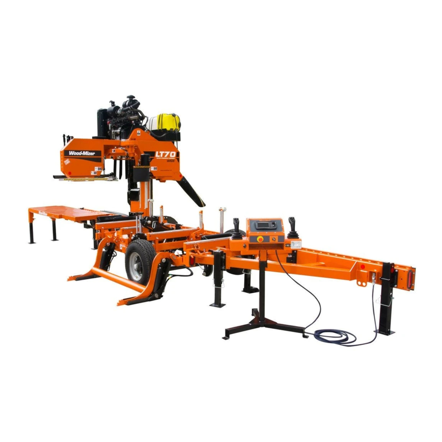
- Page 1 ® Wood-Mizer Sawmill Safety, Setup, Operation & Maintenance Manual LT70HD Remote DCS rev. B7.00 Safety is our #1 concern! Read and understand all safety information and instructions before oper- ating, setting up or maintaining this machine. Form #1708...
- Page 2 Printed in the United States of America, all rights reserved. No part of this manual may be reproduced in any form by any photographic, electronic, mechanical or other means or used in any information storage and retrieval system without written permission from Wood-Mizer 8180 West 10th Street Indianapolis, Indiana 46214...
-
Page 3: Table Of Contents
Table of Contents Section-Page SECTION 1 INTRODUCTION About This Manual.................1-1 Getting Service ..................1-2 General Contact Information..........1-2 Wood-Mizer Locations............1-3 Specifications ..................1-4 Customer and Sawmill Identification.............1-5 Warranty ....................1-7 SECTION 2 SAFETY Safety Symbols..................2-1 Safety Instructions ..................2-2 Electrical Lockout Procedures..............2-12 SECTION 3 SAWMILL SETUP Stationary Sawmill Setup ...............3-1... - Page 4 Table of Contents Section-Page Auto-Setting Feature ................4-23 Mode Selection ..............4-23 Using Auto-Down Mode............4-25 Using Auto-Up Mode ............4-26 Using Pattern Mode ............4-27 Auto-Mode Settings Menu ...........4-28 Joystick Auto-Mode Operation ...........4-32 Cutting The Log ...................4-33 4.10 Edging....................4-35 4.11 Optional Cutting Procedure..............4-36 4.12 Blade Height Scale ................4-37 4.13 Water Lube Operation ................4-39...
- Page 5 Table of Contents Section-Page SECTION 7 SAWMILL ALIGNMENT Routine Alignment Procedure ..............7-1 Blade Installation..............7-1 Saw Head Tilt ..............7-1 Blade Guide Arm Alignment ..........7-3 Blade Guide Vertical Tilt Alignment........7-7 Blade Guide Horizontal Tilt Adjustment.......7-8 Blade Guide Flange Spacing ..........7-10 Manual Side Support Alignment .........7-11 Hydraulic Side Support Alignment ........7-13 Blade Height Scale Adjustment (All Mills Except LT70 Super HD)7-14 Complete Alignment Procedure ............7-16...
-
Page 6: Introduction
The information and instructions given in this manual do not amend or extend the limited warranties for the equipment given at the time of purchase. For general information regarding Wood-Mizer and our “Forest to Final Form” products, please refer to the All Products Catalog in your support package. -
Page 7: Getting Service
Introduction Getting Service Getting Service Wood-Mizer is committed to providing you with the latest technology, best quality and strongest customer service available on the market today. We continually evaluate our customers’ needs to ensure we’re meeting current wood-processing demands. Your comments and suggestions are welcome. -
Page 8: Wood-Mizer Locations
Brazilian Headquarters European Headquarters Serving Brazil Serving Europe, Africa, West Asia Wood-Mizer do Brasil Wood-Mizer Industries Sp z o.o. Rua Dom Pedro 1, No: 205 Bairro: Sao Jose Nagorna 114 Ivoti/RS CEP:93.900-000 62-600 Kolo, Poland Tel: +55 51 9894-6461/ +55 21 8030-3338/ +55 51 Phone: +48.63.26.26.000... -
Page 9: Specifications
Introduction Specifications Specifications Model: LT70-RD Rev. B4.02+ Dimensions: Metric Wide Saw Head Only: Length: 26'-4" 8.02m 26'-4" Width: 7'-2" 2.18m 7'-8" (2.33m) Height (Ground To Mast): 7'-6" 2.28m 7'-6" Height (Max Head Position): 10'-4" 3.05m 10'-4" Bed Height (Ground To Bed): 29 1/2" 0.75m 29 1/2"... -
Page 10: Customer And Sawmill Identification
Customer and Sawmill Identification Customer and Sawmill Identification Each Wood-Mizer sawmill has a model number and a 17-digit Vehicle Identification Num- ber (VIN). In addition, when you pick up your mill, you will receive a customer number. These three numbers will help expedite our service to you. Please locate them now and write them below so you have quick, easy access to them. - Page 11 Introduction Customer and Sawmill Identification A1 017 Sample V.I.N. DESCRIPTION Introduction 60HD-Rdoc072619...
-
Page 12: Warranty
Wood-Mizer Limited Product Warranty Wood-Mizer LLC (“Warrantor”), an Indiana corporation with its principal place of business at 8180 West Tenth Street, Indianapolis, IN 46214-2400 USA, warrants to the purchaser (“Purchaser”) that for the time periods specifically stated herein and subject to the terms, conditions and limitations stated herein, the equipment... - Page 13 Introduction Warranty misuse, negligence, alterations, damage due to overload, abnormal conditions, excessive operation, acci- dent, or lack of performance of normal maintenance services. Several components which are used in the manufacture of the equipment but not manufactured by Warrantor, such as cant hooks, power plants, laser sights, batteries, tires, and trailer axles have warranties provided by the original equipment manufacturer (written copies available upon request).
- Page 14 This warranty cannot be amended, except in writing, which refers to this warranty that is signed by both Warrantor and Purchaser. © 2018 Wood-Mizer LLC – 8180 West 10 Street, Indianapolis, IN 46214...
-
Page 15: Safety
Safety Safety Symbols SECTION 2 SAFETY Safety Symbols The following symbols and signal words call your attention to instructions concerning your personal safety. Be sure to observe and follow these instructions. DANGER! indicates an imminently hazardous situation which, if not avoided, will result in death or serious injury. -
Page 16: Safety Instructions
OWNER’S RESPONSIBILITY The procedures listed in this manual may not include all ANSI, OSHA, or locally required safety procedures. It is the owner/operator’s responsibility and not Wood-Mizer Products to ensure all operators are properly trained and informed of all safety protocols. - Page 17 Failure to follow this may result in serious injury or death. WARNING! Use ONLY water and Wood-Mizer Lube Addi- tive with the water lube accessory. Never use flammable fuels or liquids such as diesel fuel. If these types of liquids are necessary to clean the blade, remove it and clean with a rag.
- Page 18 Safety Safety Instructions WARNING! Drum switch grease contains Petroleum Hydrocarbon Lubricant. Eye and skin irritant. If introduced into eyes, flush with water for at least 15 minutes. If film or irritation persists, seek medical atten- tion. Wash skin with soap and water. If ingested, do not induce vomit- ing - contact a physician.
- Page 19 Safety Safety Instructions EMERGENCY TREATMENT FOR CONTACT WITH BATTERY COMPONENTS (LEAD/SUL- FURIC ACID) per SDS (Safety Data Sheet): EYE CONTACT Sulfuric Acid and Lead: Flush eyes immediately with large amounts of water for at least 15 minutes while lifting lids. Seek immediate medical atten- tion if eyes have been exposed directly to acid.
- Page 20 Safety Safety Instructions gers are intended to support the saw frame with assistance from the trailer. WARNING! The adjustable outriggers supplied with portable sawmills are not intended for setup on concrete or other hard surfaces. Long-term use of the adjustable outriggers on hard surfaces could cause the outriggers to fail.
- Page 21 Safety Safety Instructions DANGER! Always be sure the blade is disen- gaged and all persons are out of the path of the blade before starting the engine or motor. Failure to follow this will result in serious injury or death. KEEP HANDS AWAY DANGER! Always disengage the blade and shut off the sawmill engine...
- Page 22 Safety Safety Instructions CAUTIONS FOR GAS OR DIESEL ENGINE OPERATION DANGER! Operate your engine/machine only in well ventilated areas. The exhaust gases of your engine can cause nausea, delirium and potentially death unless adequate ventilation is present. DANGER! Never operate an engine with a fuel or oil leak. The leaking fuel or oil could potentially come in contact with hot surfaces and ignite into flames.
- Page 23 Safety Safety Instructions WARNING! Never use the board return table as a platform to stand on. This table is designed and intended to assist in the removal of boards only. Standing on the table could result in serious injury or death. UP/DOWN SYSTEM SAFETY WARNING! Always secure the saw head with a 5/16"...
- Page 24 Safety Safety Instructions DANGER! Be sure that the hitch and safety chains are secure before towing the sawmill. Failure to follow this will result in serious personal injury and/or severe machine damage. DANGER! Make sure all light connections have been made and are working properly before towing the sawmill.
- Page 25 DO NOT continue to operate the mill if the main key switch does not control debarker operation. Doing so could result in serious injury or death. Call Wood-Mizer customer service for more information. USE PROPER PROCEDURE WHEN CONDUCTING ELECTRICAL SAFETY CHECKS...
-
Page 26: Electrical Lockout Procedures
Safety Electrical Lockout Procedures WARNING! Never assume or take the word of another person that the power is off; check it out and lock it out. Failure to follow this could result in shock, burns, or death. WARNING! Do not wear rings, watches, or other jewelry while working around an open electrical circuit. - Page 27 Safety Electrical Lockout Procedures FAILURE TO LOCKOUT MAY RESULT IN: Burn Crush Shock Puncture Amputation Blindness Serious injury and death Electrocution TO CONTROL MAINTENANCE DANGERS: Lockout procedures must be followed (see OSHA regulation 1910.147). Never rely on machine stop control for maintenance safety (emergency stops, on/off ...
- Page 28 Safety Electrical Lockout Procedures PURPOSE This procedure establishes the minimum requirements for the lockout of energy isolating devices whenever maintenance or servicing is done on machines or equipment. It shall be used to ensure that the machine or equipment is stopped, isolated from all potentially hazardous energy sources and locked out before personnel perform any servicing or maintenance where the unexpected enervation or start-up of the machine or equipment or release of stored energy could cause injury.
- Page 29 Safety Electrical Lockout Procedures CAUTION! Return operating control(s) to neutral or "off" position after verifying the isolation of the equipment. 8. The machine or equipment is now locked out. RESTORING EQUIPMENT TO SERVICE When the servicing or maintenance is completed and the machine or equipment is ready to return to normal operating condition, the following steps shall be taken.
-
Page 30: Sawmill Setup
Sawmill Setup Stationary Sawmill Setup SECTION 3 SAWMILL SETUP Stationary Sawmill Setup Prepare a firm, level area where the sawmill can be anchored. There should be enough room around the sawmill for operators, sawdust removal, log loading and board removal. A cement pad with 5/8”... - Page 31 Sawmill Setup Stationary Sawmill Setup See Figure 3-2. Before moving the saw carriage, remove the operator control box and stand from the travel locations at the front of the sawmill frame. 1. Remove the retaining pin securing the control stand to the travel bracket. Lift the stand from the bracket turn so the legs are at the bottom and set on the ground.
- Page 32 Sawmill Setup Stationary Sawmill Setup See Figure 3-4. Secure with lock pin in upper hole 600329 Set lower pin in stand slot FIG. 3-5 4. Place the control/stand assembly in the desired location. Connect the cable from the hydraulic pump control to the port on the back of the operator control. 5.
- Page 33 Sawmill Setup Stationary Sawmill Setup Setup the board return table for operation. 1. First, remove three retaining pins to detach the long table assembly from the sawmill. See Figure 3-6. 600187-1B FIG. 3-7 Sawmill Setup 60HD-Rdoc072619...
- Page 34 Sawmill Setup Stationary Sawmill Setup 2. Lift the long table assembly off the rest pin and slide toward the front of the mill. Rest the long table on the short bottom table so it is balanced. Replace the three retaining pins. 3.
- Page 35 Sawmill Setup Stationary Sawmill Setup 4. Pull the outrigger pins and lower the legs. See Figure 3-10. 600187-3B FIG. 3-11 5. Slide the long table until it rests in position, level with the short table assembly. 6. If necessary, adjust the outrigger legs up or down so the table is level. See Figure 3-12.
- Page 36 Sawmill Setup Stationary Sawmill Setup 7. Slide the long table until it rests in position, level with the short table assembly. 8. If necessary, remove the leg adjustment pins and adjust the legs up or down so the table is level. Replace the leg adjustment pins. See Figure 3-14.
-
Page 37: Portable Sawmill Setup
Sawmill Setup Portable Sawmill Setup Portable Sawmill Setup WARNING! Do not set up the mill on ground with more than a 10 degree incline. If setup on an incline is necessary, put blocks under one side of the mill or dig out areas for outrig- ger legs to keep mill level. - Page 38 Sawmill Setup Portable Sawmill Setup See Figure 3-16. Before moving the saw carriage, remove the operator control box and stand from the travel locations at the front of the sawmill frame. 3. Remove the retaining pin securing the control stand to the travel bracket. Lift the stand from the bracket turn so the legs are at the bottom and set on the ground.
- Page 39 Sawmill Setup Portable Sawmill Setup See Figure 3-17. Secure with lock pin in upper hole 600329 Set lower pin in stand slot FIG. 3-17 6. Place the control/stand assembly in the desired location. Connect the cable from the hydraulic pump control to the port on the back of the operator control. 7.
- Page 40 Sawmill Setup Portable Sawmill Setup Setup the board return table for operation. 1. First, remove three retaining pins to detach the long table assembly from the sawmill. See Figure 3-18. 600187-1B FIG. 3-18 3-11 60HD-Rdoc072619 Sawmill Setup...
- Page 41 Sawmill Setup Portable Sawmill Setup 2. Lift the long table assembly off the rest pin and slide toward the front of the mill. Rest the long table on the short bottom table so it is balanced. Replace the three retaining pins. 3.
- Page 42 Sawmill Setup Portable Sawmill Setup 4. Pull the outrigger pins and lower the legs. See Figure 3-20. 600187-3B FIG. 3-20 5. Slide the long table until it rests in position, level with the short table assembly. 6. If necessary, adjust the outrigger legs up or down so the table is level. See Figure 3-21.
-
Page 43: Replacing The Blade
Sawmill Setup Replacing The Blade Replacing The Blade DANGER! Always disengage the blade and shut off the sawmill engine before changing the blade. Failure to do so will result in serious injury. WARNING! Always wear gloves and eye protection when handling bandsaw blades. -
Page 44: Tensioning The Blade
Sawmill Setup Tensioning The Blade Tensioning The Blade See Figure 3-22. Before tensioning the blade, check the air pressure gauge to see that the air tension system is properly charged. With the blade tension completely released and the air bag plate against the stop bolt, the gauge should read 85 psi for all blade types. -
Page 45: Tracking The Blade
Sawmill Setup Tracking The Blade Tracking The Blade 1. Make sure the blade housing covers are closed and all persons are clear of the open side of the saw head. 2. Start the engine (or motor). 3. Engage the blade, rotating the blade until the blade positions itself on the wheels. WARNING! Do not spin the blade wheels by hand. - Page 46 Sawmill Setup Tracking The Blade 5. Use the cant adjustment bolt to adjust where the blade travels on the blade wheels. See Figure 3-1. DETAIL Turn bolt clockwise to move blade out on wheel; counterclockwise to move blade in on wheel 600001-1B Cant Adjustment Bolt...
-
Page 47: Starting The Engine (Or Motor)
Sawmill Setup Starting The Engine (or Motor) Starting The Engine (or Motor) See the appropriate manual supplied with your specific engine/motor configuration for starting and operating instructions. DANGER! Make sure all guards and covers are in place and secured before operating or towing the sawmill. Failure to do so may result in serious injury. -
Page 48: Board Return
Sawmill Setup Board Return Board Return WARNING! The automatic board return is intended to assist a second operator in removing boards quickly. Do not use the board return when operating the sawmill alone. Serious injury, death or damage to the equipment may result. - Page 49 Sawmill Setup Board Return See Figure 3-24. To bypass the board return feature, pin the board return arms in the storage position. Lock Pin Retaining Pin Rotate arms up, slide lock pin 600001-2C through holes and reinstall retaining pin FIG. 3-24 Sawmill Setup 60HD-Rdoc072619 3-20...
-
Page 50: Debarker Setup
Sawmill Setup Debarker Setup Debarker Setup Check and adjust debarker alignment as required. DANGER! Before performing any service to this equip- ment, turn the key to the OFF (0) position and remove the key. Failure to do so will result in serious injury or death. The debarker blade should be aligned to the sawmill blade to insure proper operation. - Page 51 Sawmill Setup Debarker Setup 3. Clip the blade guide alignment tool to the sawmill blade. Make sure the tool lies flat on the blade and does not contact a tooth that could cause it to angle. See Figure 3-26. Adjust bolt to move 600480-2B motor and blade up or down Loosen jam nut...
-
Page 52: Sawmill Operation
Sawmill Operation Hydraulic Control Operation (DCS) SECTION 4 SAWMILL OPERATION Hydraulic Control Operation (DCS) AC sawmill: The hydraulic controls are operational when the key switch is on except when the saw carriage is moving forward. DC sawmill: The DCS hydraulic controls become operational when the contacts at the bottom of the carriage touch the power strip on the frame tube. - Page 53 Sawmill Operation Hydraulic Control Operation (DCS) CAUTION! Always make sure the engine is running before operating the hydraulic controls. Operating the controls without the engine running will result in power drainage from the battery. Holding the joysticks halfway up or down also will cause excessive drainage from the battery.
- Page 54 Sawmill Operation Hydraulic Control Operation (DCS) See Figure 4-3. Press and hold the left joystick bottom button to place the DCS Control in Bed Mode #2. Turner Chain Clockwise If Log Deck Turner Chain Press & Hold for Option Installed: Counterclockwise Bed Mode #2 Log Deck...
- Page 55 Sawmill Operation Hydraulic Control Operation (DCS) If using the standard log loading arm, place the DCS Control in Bed Mode #1. Move the right joystick to the right to lower the loading arm as far as it will go. Logs must be rolled onto the loading arm one at a time for loading onto the bed of the mill.
-
Page 56: Loading, Turning And Clamping Logs
Sawmill Operation Loading, Turning And Clamping Logs Loading, Turning And Clamping Logs TO LOAD LOGS 1. Start the engine and move the saw carriage to the front end of the frame. CAUTION! Before loading a log, be sure the cutting head is moved far enough forward so the log does not hit it. - Page 57 Sawmill Operation Loading, Turning And Clamping Logs TO TURN LOGS 1. Engage the log turner arm. Let the arm rise until it touches the log. 2. Spin the log against the side supports until it is turned the way you want it for the first cut. TO TURN LOGS (OPTIONAL PROCEDURE) If you are turning a small cant on a mill with two-plane clamp, you may opt to use the clamp to turn the cant.
-
Page 58: Up/Down Operation (Dcs)
Sawmill Operation Up/Down Operation (DCS) Up/Down Operation (DCS) This section describes operation of the up/down system with the DCS control in manual mode. See Section 4.8 for alternate instructions for operating the up/down system in Auto or Pattern modes. 1. Install a blade, if needed, and check for correct blade tension (See Section 3.3). -
Page 59: Blade Guide Arm Operation (Dcs)
Sawmill Operation Blade Guide Arm Operation (DCS) Blade Guide Arm Operation (DCS) 1. Look down the length of the log to see its maximum width. The outer blade guide should be adjusted to clear the widest section of the log by less than 1" (25.4 mm). 2. -
Page 60: Autoclutch Operation (Dcs)
Sawmill Operation Autoclutch Operation (DCS) Autoclutch Operation (DCS) The sawmill is equipped with an automatic clutch mechanism that remotely engages/dis- engages the blade using a switch on the control box. See Figure 4-7. To engage the blade, push the blade on/off switch on the control panel. You must push the switch twice within a few seconds to activate the blade. -
Page 61: Power Feed Operation (Dcs)
Sawmill Operation Power Feed Operation (DCS) Power Feed Operation (DCS) See Figure 4-8. The power feed system moves the carriage forward and backward by using the left joystick and the feed rate switch on the control panel. Feed Forward Feed Reverse 600319-8 Feed... - Page 62 Sawmill Operation Power Feed Operation (DCS) Using The Power Feed 1. To move the carriage forward, push the left joystick forward and turn the feed rate switch clockwise. HINT: To get a straight cut in the first part of the board, feed the blade into the log at a slow speed.
-
Page 63: Dcs Control Operation
Sawmill Operation DCS Control Operation DCS Control Operation Display Overview See Figure 4-9. See a description of the various display components below. B C D E Manual Auto-Down Auto-Up Pattern 600330 FIG. 4-9 Lube-Mizer Flow Rate Laser none Option not installed Debarker none Option not installed... - Page 64 Sawmill Operation Display Overview Log Deck none Option not installed Notification none No warning or critical errors Warning detected Critical error detected Ambient Temperature Operating Voltage Engine Oil Pressure Engine Water Temperature Feed Motor Current Up/Down Motor Current Inch or MM Scale Blade Position Sawing Mode Selection Manual...
-
Page 65: Configuration
Sawmill Operation Configuration Configuration DCS controls on new sawmills are configured at the factory. If you have installed or replaced the control, be sure to configure the control as described below before operating the sawmill. See Figure 4-10. To enter User Configuration screen, push the UP button while in Man- ual Mode. -
Page 66: Language
Sawmill Operation Language Language When in User Configuration menu, use the UP/DOWN arrows to select the Regional Set- tings/Head Calibration menu. Push the CHECK button at the bottom of the display to enter. Select the Language and push the CHECK button to enter. Use the UP/DOWN arrows to select the desired language used for the DCS display. -
Page 67: Unit Of Measure
Sawmill Operation Unit of Measure Unit of Measure This setting allows to choose what units of measure, temperature and pressure are used when operating the DCS control. From the Regional Settings/Head Calibration menu, select Unit of Measure Settings and push the CHECK button to enter. Use the UP/DOWN arrows at the bottom to select the setting. -
Page 68: Head Calibration
Sawmill Operation Head Calibration Head Calibration These settings allow to calibrate the sawhead, if necessary. These settings are made at the factory and, except for the kerf, should not normally need adjusting by the operator. See Figure 4-13. Push UP/DOWN button to change setting Head Calibration Settings... -
Page 69: Engine Type
Sawmill Operation Engine Type Engine Type This menu allows you to choose the engine option used on the sawmill. From the User Configuration menu, select the Engine Type menu and push the CHECK button to enter. Use the UP/DOWN arrows at the bottom to select the engine type used on the sawmill. Push the SAVE button to save the changes and exit. -
Page 70: Dashboard Settings
Sawmill Operation Dashboard Settings Dashboard Settings You can choose what icons are shown in the upper left corner of the DCS display. From the User Configuration menu, select the Dashboard Settings menu and push the CHECK button to enter. Use the UP/DOWN arrows at the bottom to select the setting. Use the UP/DOWN buttons to change the setting. -
Page 71: System Options
Sawmill Operation System Options System Options From the User Configuration menu, select the System Options menu and push the CHECK button to enter. The System Options menu allows you to invert the joystick con- trols if sawing from the rear of the machine, or to add/remove sawmill options. The Hydraulic Offset option allows you to change the resolution of the proportional hydraulic functions. -
Page 72: Diagnostics
Sawmill Operation Diagnostics Diagnostics The Diagnostics menu allows you to check the software revisions, blade guide arm, debarker in/out motor currents (amperage), and the condition of the potentiometer. It can also be used to calibrate and troubleshoot the joystick controls. To enter the Diagnostics menu, select Diagnostics from the User Configuration menu. - Page 73 Sawmill Operation Error Log Sawmill Operation 60HD-Rdoc072619 4-22...
-
Page 74: Auto-Setting Feature
Sawmill Operation Auto-Setting Feature Auto-Setting Feature Mode Selection See Figure 4-1. To select an Auto-Set mode, press the desired Mode Select button (Man- ual, Auto-Down, Auto-Up or Pattern) located under the display. Press the Manual Mode Select button to return the control to Manual Mode. Increment Current Settings... - Page 75 Sawmill Operation Mode Selection Auto-Up Mode - This mode references the current blade height and allows you to choose an increment to move the blade up. The system will automatically move the saw head up and stop at the next increment when you push the joystick up. Auto-Up mode is primarily used to raise the saw head in large increments when preparing to cut a new log or log that has been turned.
-
Page 76: Using Auto-Down Mode
Sawmill Operation Using Auto-Down Mode Using Auto-Down Mode See Figure 4-2. In Manual Mode, Cut first face as Switch to Manual Mode position blade desired in Auto-Down and position blade for trim cut. Switch Mode then turn for trim cut. Switch to to Auto-Down and log. -
Page 77: Using Auto-Up Mode
Sawmill Operation Using Auto-Up Mode Down buttons until the desired Increment Setting is obtained. Remember to include blade kerf in your setting (i.e. If you want the finished boards to be 1" thick, set the increment to 1 1/8" to allow for typical blade kerf). The amount of kerf will depend on the thickness and tooth set of the blade you are using. -
Page 78: Using Pattern Mode
Sawmill Operation Using Pattern Mode Using Pattern Mode Starting with a new log, position the saw head at the front end of the log. Push the Pattern button under the display. Choose the desired pattern setting by pushing the appropriate Increment Setting button. In Pattern mode, a list of six increments is shown on the display. -
Page 79: Auto-Mode Settings Menu
Sawmill Operation Auto-Mode Settings Menu Auto-Mode Settings Menu The control system allows an operator to setup all the necessary auto-up/auto-down, pat- tern and reference settings by using the Auto-Mode Settings Menu. From the Main screen, enter the User Configuration menu by pressing the UP button on the right side of the display. - Page 80 Sawmill Operation Auto-Mode Settings Menu Auto-Up Settings. Select the Auto-Up Settings from the Auto Mode Settings menu to enter the Auto-Up Settings screen. Use the Increment Settings buttons to choose settings 1, 2, 3 or 4. Use the UP/DOWN arrows at the bottom of the display to highlight the set- tings you want to adjust.
- Page 81 Sawmill Operation Auto-Mode Settings Menu Pattern Settings. Select the Pattern 1 Settings from the Auto Mode Settings menu to dis- play the Pattern 1 Settings. Use the Increment Settings buttons to choose settings A, B, C or D. Use the UP/DOWN arrows at the bottom of the display to highlight the settings you want to adjust.
- Page 82 Sawmill Operation Auto-Mode Settings Menu Reference Settings. Select the Reference Settings from the Auto Mode Settings menu to enter the Reference Settings menu. Use the UP/DOWN arrows at the bottom of the display to highlight the settings you want to adjust. Use the UP/DOWN buttons on the right side of the display to adjust the setting.
-
Page 83: Joystick Auto-Mode Operation
Sawmill Operation Joystick Auto-Mode Operation Joystick Auto-Mode Operation You can use the left and right joysticks to switch to the desired auto-mode setting. Press the top left button on the left joystick to toggle between Manual Mode and the most recently used auto-mode setting. -
Page 84: Cutting The Log
Cutting The Log Cutting The Log The following steps guide you through normal operation of the Wood-Mizer sawmill. 1. Once the log is placed where you want it and clamped firmly, move the saw head to posi- tion the blade close to the end of the log. - Page 85 Sawmill Operation Cutting The Log 9. Lower the toe boards, if they were used. Use the joysticks in bed mode to release the clamp and engage the log turner. Turn the log 90 or 180 degrees. Make sure the flat on the log is placed flat against side supports if turned 90 degrees.
-
Page 86: 4.10 Edging
Sawmill Operation Edging 4.10 Edging 1. Raise the side supports to 1/2 the height of the flitches, or the boards that need to be edged. 2. Stack the flitches on edge against the side supports. 3. Clamp the flitches against the side supports halfway up the flitch height. (Wider flitches should be placed to the clamp side. -
Page 87: 4.11 Optional Cutting Procedure
Sawmill Operation Optional Cutting Procedure 4.11 Optional Cutting Procedure In order to achieve maximum production rates, it may be desirable to leave the blade engaged when returning the carriage. (Normal operation procedures recommend disen- gaging the blade before returning the carriage for maximum blade life and fuel economy.) DANGER! If leaving the blade engaged for maximum pro- duction rates, make sure the off-bearer stays out of the path... -
Page 88: 4.12 Blade Height Scale
Sawmill Operation Blade Height Scale 4.12 Blade Height Scale The blade height scale is attached to the carriage head frame. It includes: a blade height indicator an inch scale a quarter scale See Figure 4-18. Blade Height Indicator Quarter Scale... - Page 89 Sawmill Operation Blade Height Scale THE QUARTER SCALE Two quarter scales are provided with four sets of marks. Each set represents a specific lumber thickness. Saw kerf and shrinkage allowance are included, but actual board thick- ness will vary slightly depending on blade thickness and tooth set. To choose which scale to use, determine what finished thickness you want to end up with.
-
Page 90: 4.13 Water Lube Operation
15 seconds. This will clean the blade of sap buildup. Wipe the blade dry with a rag before storing or sharpening. For further lubrication benefits, add one 12oz. (0.35L) bottle of Wood-Mizer Lube Additive to 5 gallons (18.9 liters) of water. Wood-Mizer Lube Additive enables some previously impossible timbers to be cut by significantly reducing resin buildup on the blade. - Page 91 Sawmill Operation Water Lube Operation WARNING! Use ONLY water and Wood-Mizer Lube Additive with the water lube accessory. Never use flammable fuels or liquids such as diesel fuel. If these types of liquids are necessary to clean the blade, remove it and clean with a rag. Failure to do so can damage the equip- ment and may result in serious injury or death.
-
Page 92: 4.14 Preparing The Sawmill For Towing
Preparing The Sawmill For Towing 4.14 Preparing The Sawmill For Towing The Wood-Mizer trailer package makes transporting your sawmill easy and convenient. To get your sawmill ready for towing, follow these instructions. 1. Move the saw carriage to the front end of the sawmill. Raise the rear outriggers See the Fine Adjust Outrigger (FAO) manual for outrigger operation instructions.. - Page 93 Sawmill Operation Preparing The Sawmill For Towing adjusted to secure the carriage on the track rail. Failure to properly adjust the stop bolt can cause saw head damage, especially during mill transportation. 9. If necessary, adjust the stop located at the bottom of the mast so the saw head contacts the stop after it is lowered 3/4"...
- Page 94 Sawmill Operation Preparing The Sawmill For Towing 12. Hook the carriage safety chain located at the bottom of the carriage to the bracket at the bottom of the mast. See Figure 4-22. Safety Chain Bracket Safety chain 600412-3 FIG. 4-22 CAUTION! Check to be sure the saw head safety chain is secured before towing the sawmill.
-
Page 95: Maintenance
Maintenance Wear Life SECTION 5 MAINTENANCE This section lists the maintenance procedures that need to be performed. See the Maintenance chart located after this section for a complete list of maintenance procedures and intervals. Keep a log of machine maintenance by recording in the machine hours and the date you perform each procedure. -
Page 96: Blade Guides
Maintenance Blade Guides Blade Guides WARNING! Before performing service near moving parts such as blades, pulleys, motors, belts and chains, first turn the key switch to the OFF (#0) position and remove the key. If the key is turned on and moving parts activated, serious injury may result. - Page 97 If the wood you are sawing leaves sap buildup using plain water in the blade lube system, use Wood-Mizer lube additive (4-Pak 60 oz. bottles part no. ADD-1). 5. Make sure the blade screw in the top center of the C-frame is 1/16" (1.5 mm) away from the blade.
-
Page 98: Sawdust Removal
Maintenance Sawdust Removal Sawdust Removal WARNING! Before performing service near moving parts such as blades, pulleys, motors, belts and chains, first turn the key switch to the OFF (#0) position and remove the key. If the key is turned on and moving parts activated, serious injury may result. -
Page 99: Carriage Track, Wiper & Scraper
Maintenance Carriage Track, Wiper & Scraper Carriage Track, Wiper & Scraper WARNING! Before performing service near moving parts such as blades, pulleys, motors, belts and chains, first turn the key switch to the OFF (#0) position and remove the key. If the key is turned on and moving parts activated, serious injury may result. - Page 100 Maintenance Carriage Track, Wiper & Scraper 3. Check the track scrapers as needed. Make sure the scrapers fit firmly against the rail. If a track scraper needs to be adjusted, loosen the screw, push the scraper downward until it fits firmly against the rail, and retighten the screw. See Figure 5-3.
-
Page 101: Vertical Mast Rails
Maintenance Vertical Mast Rails Vertical Mast Rails WARNING! Before performing service near moving parts such as blades, pulleys, motors, belts and chains, first turn the key switch to the OFF (#0) position and remove the key. If the key is turned on and moving parts activated, serious injury may result. -
Page 102: Miscellaneous
Maintenance Miscellaneous Miscellaneous WARNING! Before performing service near moving parts such as blades, pulleys, motors, belts and chains, first turn the key switch to the OFF (#0) position and remove the key. If the key is turned on and moving parts activated, serious injury may result. 1. -
Page 103: Blade Tensioner
Maintenance Blade Tensioner Blade Tensioner WARNING! Before performing service near moving parts such as blades, pulleys, motors, belts and chains, first turn the key switch to the OFF (#0) position and remove the key. If the key is turned on and moving parts activated, serious injury may result. -
Page 104: Blade Wheel Belts
Rotate the blade wheel belts and check them for wear. Rotating the belts every 50 hours will provide longer belt life. Replace belts as necessary. Use only B72.5 belts supplied by Wood-Mizer. 5-10 60HD-Rdoc072619... -
Page 105: Drive Belt Adjustment
See Table 5-2. See the table below for drive belt tension specifications for your model sawmill. Measure the belt tension with a gauge. NOTE: Wood-Mizer offers a belt tension gauge (Part No. 016309) that will let you accurately measure the belt tension. -
Page 106: Adjust Belt Tension
Maintenance Adjust belt tension Adjust belt tension 1. Turn the key switch to the accessory (#3) position. Engage the drive belt with the blade switch on the control panel. 2. Turn the key switch to the off (#0) position and remove the key. Check the belt tension as described above. -
Page 107: Adjust The Drive Belt Support (Excludes E25, E30, D55)
Maintenance Adjust the drive belt support (Excludes E25, E30, D55) Adjust the drive belt support (Excludes E25, E30, D55) The drive belt support is designed to extend belt life. The bracket should be adjusted to NOT touch the drive belt when the clutch handle is engaged (down position), AND to hold the drive belt away from the engine pulley when the clutch handle is disengaged (up posi- tion). -
Page 108: Brake Adjustment (Dc Only)
Maintenance Brake Adjustment (DC Only) 5.10 Brake Adjustment (DC Only) WARNING! Before performing service near moving parts such as blades, pulleys, motors, belts and chains, first turn the key switch to the OFF (#0) position and remove the key. If the key is turned on and moving parts activated, serious injury may result. -
Page 109: Autoclutch Belt (Dc Only)
Tighten the belt to 1/16” deflec- tion with 1/4 lb. deflection force. Wood-Mizer offers a belt tension gauge (Part No. 016309) that will let you accurately measure the belt tension. -
Page 110: 5.12 Hydraulic System
Maintenance Hydraulic System 5.12 Hydraulic System WARNING! Disconnect and lockout power before performing any ser- vice to the electrical system. For battery-powered equipment, discon- nect the negative battery terminal cable. For AC-powered equipment, follow the lockout procedure provided in the safety section (See Sec- tion 2.3). - Page 111 Maintenance Hydraulic System 2. Replace the hydraulic system cartridge filter every 500 hours of operation. 3. DC Only: Inspect the hydraulic pump motor brushes every 750 hours of operation. Remove brush dust and replace the brushes if they worn to a length of 1/4” (6mm) or shorter.
-
Page 112: 5.13 Up/Down System
Maintenance Up/Down System 5.13 Up/Down System WARNING! Before performing service near moving parts such as blades, pulleys, motors, belts and chains, first turn the key switch to the OFF (#0) position and remove the key. If the key is turned on and moving parts activated, serious injury may result. - Page 113 Drain and refill the gearbox with 40 (1.2L) ounces of oil after every 5000 hours of sawmill operation or every year, whichever comes first. Wood-Mizer offers replacement gear oil in 8 ounce (0.24L) bottles. 7. Inspect the up/down motor brushes every 750 hours of operation. Remove brush dust and replace the brushes if they worn to a length of 5/8”...
- Page 114 Maintenance Up/Down System 1. Locate the four upper up/down assist mounting bolts. Remove the two lower set of mounting bolts. See Table 5-3. Remove bottom two upper mountng bolts 600188-2 FIG. 5-11 2. Raise the saw head all the way to the top of the mast and secure with a chain. 3.
- Page 115 Maintenance Up/Down System See Figure 5-12. 600188B Loosen Lower Mounting Bolts (4) Turn Tension Bolt Counterclockwise to Remove Tension FIG. 5-12 4. Loosen (do NOT remove) the four lower mounting bolts to allow the bracket to move along the slotted mounting holes. 5.
- Page 116 Maintenance Up/Down System See Figure 5-13. Secure the chain at the top of the assist assembly to prevent it from fall- ing down into the tube. Secure chain at top of assist assembly Remove remaining two upper mounting bolts FIG. 5-13 7.
-
Page 117: 5.14 Power Feed
Maintenance Power Feed 5.14 Power Feed WARNING! Before performing service near moving parts such as blades, pulleys, motors, belts and chains, first turn the key switch to the OFF (#0) position and remove the key. If the key is turned on and moving parts activated, serious injury may result. - Page 118 Drain and refill the gearbox with 12 - 15 ounces (0.35 - 0.44L) of oil after every 5000 hours of sawmill operation or every 2 years, whichever comes first. Wood-Mizer offers replacement gear oil in 8 ounce (0.24L) bottles. 5-24...
-
Page 119: Charging The Battery (Dc Only)
Maintenance Charging The Battery (DC Only) 5.15 Charging The Battery (DC Only) DANGER! Batteries expel explosive gases. Keep sparks, flames, burning cigarettes, or other ignition sources away at all times. Always wear safety goggles and a face shield when working near batteries. Failure to do so will cause serious injury. - Page 120 Maintenance Charging The Battery (DC Only) 1. Raise the saw head to access the battery box. 2. Turn the key to the OFF (#0) position and remove the key. 3. Remove the two wing nuts and flat washers holding the battery box lid to the battery box. 4.
-
Page 121: 5.16 Festoon Replacement
Maintenance Festoon Replacement 5.16 Festoon Replacement Follow the steps below to replace the festoon assembly (Kit #076080) on the LT70 DCS sawmills equipped with the previous version of the festoon: 1. Use the sawmill controls to move the saw carriage so the hydraulic power strip (if applica- ble) is not engaged and raise the saw head to gain access to the battery box lid. - Page 122 Maintenance Festoon Replacement 5. Replace the exiting pulley and the bushing located at the upper pulley mount with the pro- vided pulley. Use the provided hex head bolt, the provided fender washer, the existing washers and the hex nylon lock nut to secure the pulley to the upper pulley mount as shown below.
- Page 123 Maintenance Festoon Replacement 7. Replace the existing pulleys located at the back of the distribution box with the three pro- vided pulleys. Route the guide cable on the pulleys and install the pulley guard plate. Use the provided 1/2-13 x 2" hex head bolts to secure the pulleys and the pulley guard plate in place.
- Page 124 Maintenance Festoon Replacement 10. Replace the existing cable trolleys with the provided cable trolleys. IMPORTANT: Replace the cable trolleys one at a time maintaining the natural coil of the wire. It may be necessary to reorient the cable clamp so the smaller cable hole is oriented down as shown below.
-
Page 125: 5.17 Maintenance Chart
Maintenance Maintenance chart 5.17 Maintenance chart MAINTENANCE LOG MANUAL MAINTENANCE (Check Engine And Option Manuals for additional REFERENCE INTERVAL maintenance procedures) Clean sawdust from hydraulic loader fuses , battery box lid See Section 5.3 8 hours & track cover Clean and lubricate top/bottom track See Section 5.4 8 hours Check blade guide Block/roller wear... -
Page 126: Troubleshooting Guide
Troubleshooting Guide Sawing Problems SECTION 6 TROUBLESHOOTING GUIDE Sawing Problems WARNING! Before performing service near moving parts such as blades, pulleys, motors, belts and chains, first turn the key switch to the OFF (#0) position and remove the key. If the key is turned on and moving parts activated, serious injury may result. - Page 127 Troubleshooting Guide Sawing Problems PROBLEM CAUSE SOLUTION Tooth set problems Resharpen and reset blade Sawdust Builds Up On Track Excessive oiling Do not oil track Track wipers worn Adjust wipers to firmly contact track Track is sticky Clean track with solvent and apply silicone spray Wavy Cuts Excessive feed...
-
Page 128: Hydraulic Problems
Replace solenoid if necessary. NOTE: The ing solenoid solenoid is not a standard automotive type. Order from Wood-Mizer only Defective pump motor Remove motor from pump and inspect. Repair or replace as necessary HDdoc072619... - Page 129 Troubleshooting Guide Hydraulic Problems PROBLEM CAUSE SOLUTION You Can Get Response Valve assembly switch Locate the valve switch at the bottom of the From the Pump By Actuat- contacts are not properly valve assembly. Use a 3MM allen wrench to ing All But One or Two adjusted loosen the set screw on each of the five...
- Page 130 Troubleshooting Guide Hydraulic Problems PROBLEM CAUSE SOLUTION Low air temperature caus- Allow fluid to warm up. Synthetic fluids are ing fluid to thicken available that allow for hydraulic operation in cold weather conditions (Univis HVI 13) Hydraulic Turner Goes Up Dirt in sequence valve Remove sequence valves and clean thor- Before Or At Same Time...
- Page 131 Troubleshooting Guide Hydraulic Problems PROBLEM CAUSE SOLUTION Bad check valve (results Check the release valve as instructed in one of the toe boards above. If the release valve is good, replace experiencing down-creep) the high-pressure hydraulic check valves (A12869) located on the pump. Pump runs but makes Low fluid level Check fluid level and add fluid as neces-...
-
Page 132: Hydraulic Pressure Test
Troubleshooting Guide Hydraulic Pressure Test Hydraulic Pressure Test TO CHECK HYDRAULIC PRESSURE: See Figure 6-1. Relief Valve Adjustment Screw Hydraulic Pressure 600200-2 Gauge FIG. 6-1 Operate the loading arm hydraulic lever and read the pressure on the gauge. Hydraulic pressure is factory-set at 2200 psi and should not need to be readjusted. The relief valve adjustment screw shown may be used to fine-tune the hydraulic pressure: Remove the adjustment screw nut. -
Page 133: Engine/Motor And Drive Pulleys Alignment
Troubleshooting Guide Engine/Motor and Drive Pulleys Alignment Engine/Motor and Drive Pulleys Alignment WARNING! Before performing service near moving parts such as blades, pulleys, motors, belts and chains, first turn the key switch to the OFF (#0) position and remove the key. If the key is turned on and moving parts activated, serious injury may result. -
Page 134: Dcs Error Codes
Troubleshooting Guide DCS Error Codes DCS Error Codes See Table 6-1. NOTE: The information in the first 4 columns of this chart is provided on the front panel during an error. TITLE ERROR PROBLEM RECOMMENDED ADDITIONAL INFORMATION CODE USER ACTIONS Joystick Left Joy- 1) Inspect harness for... - Page 135 Troubleshooting Guide DCS Error Codes Engine Shut- Oil Pressure 1) Check oil level. The E05 error code indicates the ECM has detected low oil pres- down Too Low 2) Consult the man- sure as sensed by the Oil Pressure Sending Unit on the engine. ual.
- Page 136 Troubleshooting Guide DCS Error Codes Auto-Clutch Auto-Clutch 1) Verify Auto-Clutch The E09 error code indicates that the ECM has detected an Error Undetected is plugged in. open-load condition with the Autoclutch motor. This can be caused 2) Inspect motor wir- by the motor not being plugged in, loose/broken connec- ing for damage.
- Page 137 Troubleshooting Guide DCS Error Codes Debarker Current Too 1) Verify Debarker The E12 error code indicates that the ECM is detecting that the In/Out Error High arm is not binding. Debarker in/out motor is drawing too much current. This can be 2) Inspect motor wir- caused by a mechanical bind, damaged (shorted) wiring, or defec- ing for damage.
- Page 138 Troubleshooting Guide DCS Error Codes Lubemizer Current Too 1) Inspect pump wir- The E16 error code indicates the ECM has detected that the circuit Error High ing for damage. for the Lubemizer pump is drawing too much current. This can be 2) Inspect pump for caused by damaged (shorted) wiring to the pump, debris in the obstruction.
- Page 139 Troubleshooting Guide DCS Error Codes Communica- ECM Com- 1) Verify communica- The E19 error code indicates that the system has lost the ability to tion Error munication tion cable is plugged communicate via the CANBus with the ECM. Loss Possible Solution(s): 2) Consult the man- If the system is communicating with all of the other modules (as ual.
- Page 140 Troubleshooting Guide DCS Error Codes Debarker Debarker 1) Inspect solenoid The E26 error code indicates that the circuit for the Debarker sole- Blade Motor Motor Sole- wiring for damage noid is drawing too much current or that solenoid is not detected noid 2) Test Debarker sole- (open).
- Page 141 Troubleshooting Guide DCS Error Codes Glow Plug 2 Current too 1) Inspect wiring for The E33 error code indicates the ECM has detected that glow plug damage. #2 is not drawing enough current. This can be caused by faulty 2) Test Glow Plug. connections, damaged (open) wiring going to the glow plug, a 3) Consult the man- burned out (open) glow plug, or a defective circuit within the ECM.
- Page 142 Troubleshooting Guide DCS Error Codes Glow Plug 3 Current too 1) Inspect wiring for The E38 error code indicates the ECM has detected that glow plug damage. #3 is drawing too much current. This can be caused by damaged 2) Consult the man- (shorted) wiring going to the glow plug, a shorted glow plug, or a ual.
- Page 143 Troubleshooting Guide DCS Error Codes Auto-Clutch Clutch is 1) Disengage clutch The E44 error code is displayed when the ECM detects that the Error engaged before starting Autoclutch (blade) is not fully disengaged. This safety feature engine. keeps the engine from cranking until the Autoclutch is disengaged to prevent unexpected blade movement, excessive starter load, and excessive drain on the battery.
- Page 144 Troubleshooting Guide DCS Error Codes AC Drive Power Sup- 1) For/Rev AC Drive The E48 error code indicates that the 24V power supply on the for- Power Sup- ply voltage 24v power supply ward/reverse AC inverter drive has dropped below 18V. This can overloaded.
- Page 145 Troubleshooting Guide DCS Error Codes Starter Sole- Starter 1) Make sure starter The E57 error code indicates the ECM has detected that the noid Error Solenoid solenoid is plugged in. starter solenoid circuit is not pulling enough current (open circuit). Undetected 2) Inspect wiring for This can be caused by damaged (open) wiring from The ECM to...
- Page 146 Troubleshooting Guide DCS Error Codes See Table 6-2. The HCM Error Codes are shown below. // Bed Mode 1 Code ERROR_OUTPUT_CLAMP_OUT ERROR_OUTPUT_CLAMP_IN ERROR_OUTPUT_CLAMP_DOWN ERROR_OUTPUT_CLAMP_UP ERROR_OUTPUT_LOAD_DOWN ERROR_OUTPUT_LOAD_UP ERROR_OUTPUT_FRONT_PINCH_OUT ERROR_OUTPUT_FRONT_PINCH_IN // Bed Mode 2 Code ERROR_OUTPUT_TURNER_DOWN ERROR_OUTPUT_TURNER_UP ERROR_OUTPUT_TURN_SPIN_CCW ERROR_OUTPUT_TURN_SPIN_CW ERROR_OUTPUT_LOGDECK_OUT ERROR_OUTPUT_LOGDECK_IN // Bed Mode 3 Code ERROR_OUTPUT_FRONT_PINCH_DOWN ERROR_OUTPUT_FRONT_PINCH_UP...
-
Page 147: Sawmill Alignment
Routine Alignment Procedure SECTION 7 SAWMILL ALIGNMENT The Wood-Mizer sawmill is factory aligned. Two alignment procedures are available to realign the sawmill if necessary. The Routine Alignment instructions should be performed as necessary to solve sawing problems not related to blade performance. The Complete Alignment procedure should be performed approximately every 1500 hours of operation (sooner if you regularly transport the sawmill over rough terrain). - Page 148 Sawmill Alignment Saw Head Tilt See Figure 7-1. A + 1/16” SM0257 FIG. 7-1 3. Measure from the blade to the bed rail near the outer blade guide assembly. This mea- surement should be 1/16" (1.5 mm) higher than the inner measurement or 14 13/16" (376.5 mm).
-
Page 149: Blade Guide Arm Alignment
Sawmill Alignment Blade Guide Arm Alignment See Figure 7-2. To adjust the saw head tilt, use the bolts located at the bottom of the saw head mast. Loosen the three sets of four retaining plate bolts. To raise the outside of the saw head, back the stop bolts out, then tighten the adjustment bolts. - Page 150 Sawmill Alignment Blade Guide Arm Alignment See Figure 7-3. Loosen the jam nuts and turn the adjustment bolts in to tighten the blade guide arm rollers. Retighten the jam nuts. 600025B Roller Adjustment Bolts FIG. 7-3 After tightening the blade guide arm rollers, check that the arm is aligned properly. 3.
- Page 151 Sawmill Alignment Blade Guide Arm Alignment 4. Adjust the blade guide arm to 1/2" (12.7 mm) from fully open and remeasure the distance from the roller flange to the back of the blade. The two measurements should be the same. If not, adjust the outer rollers in or out to tilt the arm horizontally. See Figure 7-5.
- Page 152 Sawmill Alignment Blade Guide Arm Alignment See Figure 7-6. Measure from blade guide arm to bed rail with arm open and closed 600025-2B FIG. 7-6 7. Adjust the blade guide arm to 1/2" (13 mm) from fully open. Measure the distance from the bottom of the blade guide mounting block to the bed rail.
-
Page 153: Blade Guide Vertical Tilt Alignment
Sawmill Alignment Blade Guide Vertical Tilt Alignment See Figure 7-7. Loosen the vertical adjustment bolt jam nuts. To tilt the blade guide arm down, loosen the rear bolt and tighten the front bolt. To tilt the blade guide arm up, loosen the front bolt and tighten the rear bolt. -
Page 154: Blade Guide Horizontal Tilt Adjustment
Sawmill Alignment Blade Guide Horizontal Tilt Adjustment 3. Move the carriage so that the front end of the tool is positioned above the bed rail. Mea- sure the distance from the bed rail to the bottom edge of the tool. 4. - Page 155 Sawmill Alignment Blade Guide Horizontal Tilt Adjustment 9. Remove the clip from the blade guide alignment tool. Place the tool against the face of the outer blade guide roller. See Figure 7-10. Horizontal Tilt 600244-6 Adjustment Screws Blade Guide Alignment Tool FIG.
-
Page 156: Blade Guide Flange Spacing
Sawmill Alignment Blade Guide Flange Spacing See Figure 7-11. Loosen the jam nuts on the horizontal tilt adjustment screws. To tilt the roller left, loosen the right screw and tighten left screw. To tilt the roller right, loosen the left screw and tighten the right screw. Tighten the jam nuts and recheck the tilt of the blade. -
Page 157: Manual Side Support Alignment
Sawmill Alignment Manual Side Support Alignment Retighten the screws and jam nuts. Adjust the stop bolt against the blade guide assembly. Loosen top and 600214-1 one side adjustment screw Stop Bolt 1/16” (Inner Blade Guide) 1/8” (Outer Blade Guide) FIG. 7-12 2. - Page 158 Sawmill Alignment Manual Side Support Alignment than 1/32" (0.8 mm) greater than the distance at the base of the side support (’A’). Adjust the horizontal tilt of the side support if necessary. See Figure 7-13. Loosen the two adjustment plate mounting bolts. Use a mallet to move the plate until the side support is parallel to the bed tube in the horizontal position.
-
Page 159: Hydraulic Side Support Alignment
Sawmill Alignment Hydraulic Side Support Alignment See Figure 7-14. Loosen the side support mounting bolt. Use a 3/8" ratchet to rotate the pin until the side support is square to the bed. Alignment Tubes (2) Place square against side support Loosen mounting bolt SM0272-1 Use 3/8”... -
Page 160: Blade Height Scale Adjustment (All Mills Except Lt70 Super
Sawmill Alignment Blade Height Scale Adjustment (All Mills Except LT70 Super HD) See Figure 7-15. Loosen the top jam nut. Adjust the two lower jam nuts up to tilt the side support back. Adjust the two lower jam nuts down to tilt the side support forward. Retighten the top jam nut and repeat for the other hydraulic side support. - Page 161 Sawmill Alignment Blade Height Scale Adjustment (All Mills Except LT70 Super HD) For example, if the measurement from the down-set tooth of the blade to the bed rail was 14 3/4" (375 mm), make sure the indicator reads 14 3/4" (375 mm) on the scale. Blade Height Indicator Scale Bracket...
-
Page 162: Complete Alignment Procedure
Sawmill Alignment Complete Alignment Procedure Complete Alignment Procedure Frame Setup Before performing the following alignment procedures, setup the mill on firm, level ground. If your sawmill is stationary, with no trailer axle, shim the feet so the weight of the sawmill is evenly supported. -
Page 163: Blade Wheel Alignment
Sawmill Alignment Blade Wheel Alignment 8. Engage the blade, rotating the blade until the blade positions itself on the wheels. WARNING! Do not spin the blade wheels by hand. Spinning the blade wheels by hand may result in serious injury. 9. - Page 164 Sawmill Alignment Blade Wheel Alignment nut on the top adjustment screw and tighten the screw. Tighten the top and bottom jam nuts. 600025-4C Adjust vertical adjustment screws up to tilt drive-side blade wheel down; Adjust screws down to tilt wheel up FIG.
- Page 165 Sawmill Alignment Blade Wheel Alignment nut on the bottom adjustment screw and tighten the screw. Tighten the top and bottom jam nuts. 600025-5B Adjust vertical adjustment screws up to tilt idle-side blade wheel down; Adjust screws down to tilt wheel up FIG.
- Page 166 Sawmill Alignment Blade Wheel Alignment mm]).The gullet of an 1-1/2" blade should be 3/16" (4.5 mm) out from the front edge of the wheel (±1/16 [1.5 mm]). Do not let the teeth ride on the wheels. SM0044D 1/8" (3.0 mm) ±...
-
Page 167: Track Roller Adjustment
Sawmill Alignment Track Roller Adjustment See Figure 7-23. Use the horizontal adjustment screw to adjust the drive-side blade wheel. Loosen the top vertical screw to allow movement of the drive shaft. To move the blade back on the wheel, loosen the jam nut and turn the horizontal adjustment screw clockwise one quarter turn. To move the blade out on the wheel, loosen the jam nut and turn the horizontal adjust- ment screw counterclockwise one quarter turn. - Page 168 Sawmill Alignment Track Roller Adjustment See Figure 7-25. Upper Track Rollers Stop Bolt Adjustment Bolt Retainer Plate Bolts (4) Lower Track 600011-7 Roller Lower Stop FIG. 7-25 Loosen the four retaining plate bolts. Back out the stop bolt and tighten the adjustment bolt to move the track roller(s) toward the rail.
- Page 169 Sawmill Alignment Track Roller Adjustment See Figure 7-26. 17" (400 mm) to blade SM0137 FIG. 7-26 5. Move the carriage forward to check the distance to the blade at the inside of the pivot rail support. All measurements should be equal within 1/32" (0.8 mm). See Figure 7-27.
-
Page 170: Bed Rail Adjustment
Sawmill Alignment Bed Rail Adjustment side of the saw head, loosen the adjustment bolts and tighten the stop bolts. Recheck the saw head tilt and readjust the bolts as necessary. Retighten the retaining plate bolts. Stop Bolt Retaining Adjustment Bolt Plate Bolts 600011-4B Tighten adjustment... - Page 171 Sawmill Alignment Bed Rail Adjustment 3. Move the saw head to center the blade over the front pivot bed rail. 4. Measure the distance from the top of the pivot rail to the bottom of the blade. Make this measurement at each end of the pivot rail. 5.
-
Page 172: Blade Guide Installation
Blade Guide Installation Each Wood-Mizer sawmill has two blade guide assemblies that help the blade maintain a straight cut. The two blade guide assemblies are positioned on the saw head to guide the blade on each side of the material being cut. - Page 173 Sawmill Alignment Blade Guide Installation See Figure 7-30. Inspect the guide blocks and repair or replace as necessary. Remove the blade from the sawmill. 600244-7 Insert guide assembly into mounting block Loosen top disk mounting bolt and clamp bolt Turn adjustment bolt counterclockwise to raise top disk all the way up...
-
Page 174: Blade Guide Arm Alignment
Sawmill Alignment Blade Guide Arm Alignment See Figure 7-31. Turn bolt clockwise to raise assembly so roller does not touch 600214-2 the blade Tighten tilt screws to secure blade guide assembly Adjust stop bolt to touch blade guide bracket FIG. 7-31 Blade Guide Arm Alignment The blade guide arm moves the outer blade guide in and out. - Page 175 Sawmill Alignment Blade Guide Arm Alignment See Figure 7-32. Loosen the jam nuts and turn the adjustment bolts in to tighten the blade guide arm rollers. Retighten the jam nuts. 600025B Roller Adjustment Bolts FIG. 7-32 Sawmill Alignment 60HD-Rdoc072619 7-29...
- Page 176 Sawmill Alignment Blade Guide Arm Alignment After tightening the blade guide arm rollers, check that the arm is aligned properly. 3. With the arm adjusted 1/2" (13 mm) from fully closed, measure the distance between the blade guide roller flange and the back of the blade. See Figure 7-33.
- Page 177 Sawmill Alignment Blade Guide Arm Alignment blade, loosen the front bolt and tighten the rear bolt. Retighten the jam nuts and recheck the blade guide arm horizontal tilt. 600025-1B Front Horizontal Rear Horizontal Adjustment Bolt Adjustment Bolt FIG. 7-34 5. Now check the vertical tilt of the blade guide arm. Move the saw carriage so the blade guide arm is positioned over a bed rail.
- Page 178 Sawmill Alignment Blade Guide Arm Alignment surement should be 15" (376.5 mm). If the measurements are not the same, adjust the blade guide arm vertically. Measure from blade guide arm to bed rail with arm open and closed 600025-2B FIG. 7-35 See Figure 7-36.
-
Page 179: Blade Guide Deflection
Sawmill Alignment Blade Guide Deflection Blade Guide Deflection 7. Raise the saw head until the blade is 15" (375 mm) above a bed rail. Measure the actual distance with a tape from the top of the rail to the bottom of the blade. See Figure 7-37. - Page 180 Sawmill Alignment Blade Guide Vertical Tilt Alignment See Figure 7-38. Clip tool to blade SM0069B FIG. 7-38 3. Move the carriage so that the front end of the tool is positioned above the bed rail. Mea- sure the distance from the bed rail to the bottom edge of the tool. 4.
-
Page 181: Blade Guide Horizontal Tilt Adjustment
Sawmill Alignment Blade Guide Horizontal Tilt Adjustment 8. After adjusting the vertical tilt of the blade guides, recheck the blade deflection and adjust if necessary. Blade Guide Horizontal Tilt Adjustment If the blade guides are tilted in the wrong direction horizontally, the back of the blade may contact the flange as the roller is spinning down, causing it to push the blade away from the guide roller. -
Page 182: Blade Guide Flange Spacing
Sawmill Alignment Blade Guide Flange Spacing NOTE: Once the blade guides have been adjusted, any cutting vari- ances are most likely caused by the blade. See Blade Handbook, Form #600. Blade Guide Flange Spacing Each blade guide must be adjusted so the roller flange is the correct distance from the back edge of the blade. -
Page 183: Blade Guide Level
Sawmill Alignment Blade Guide Level Blade Guide Level Perform the following adjustments to make sure the blade guide assembly is parallel to the blade. 1. Loosen the alignment bar mounting bolt. Use the provided bottom block adjustment tool to adjust the alignment bar up so the bar is close to, but not touching the bottom of the blade. -
Page 184: Manual Side Support Alignment
Sawmill Alignment Manual Side Support Alignment mounting bolts loose). Use the provided bottom block adjustment tool to lower the bottom block all the way down. Install, tension and track the blade. See Figure 7-43. 600214-4 Turn adjustment bolt clockwise to lower top block Tighten mounting bolt and clamp bolt... - Page 185 Sawmill Alignment Manual Side Support Alignment than 1/32" (0.8 mm) greater than the distance at the base of the side support (’A’). Adjust the horizontal tilt of the side support if necessary. See Figure 7-44. Loosen the two adjustment plate mounting bolts. Use a mallet to move the plate until the side support is parallel to the bed tube in the horizontal position.
-
Page 186: Hydraulic Side Support Alignment
Sawmill Alignment Hydraulic Side Support Alignment See Figure 7-45. Loosen the side support mounting bolt. Use a 3/8" ratchet to rotate the pin until the side support is square to the bed. Alignment Tubes (2) Place square against side support Loosen mounting bolt SM0272-1 Use 3/8”... -
Page 187: Clamp Stop/Stop Bolt Adjustment
Sawmill Alignment Clamp Stop/Stop Bolt Adjustment See Figure 7-46. Loosen the top jam nut. Adjust the two lower jam nuts up to tilt the side support back. Adjust the two lower jam nuts down to tilt the side support forward. Retighten the top jam nut and repeat for the other hydraulic side support. -
Page 188: Saw Head Tilt
Sawmill Alignment Saw Head Tilt See Figure 7-47. Loosen the clamp stop bolts and adjust the clamp stop until it touches the string. Loosen the jam nut and adjust the bolt on the middle-rear bed rail until it touches the string. Adjust stop bolt against string String across... - Page 189 Sawmill Alignment Saw Head Tilt 1. Move the saw carriage so the blade is positioned over a bed rail. Adjust the blade guide arm to 1/2" (13 mm) from full open. The saw head should still be adjusted so the blade is 14 3/4"...
-
Page 190: Blade Height Scale Adjustment (All Mills Except Lt70 Super
Sawmill Alignment Blade Height Scale Adjustment (All Mills Except LT70 Super HD) bolts until the outside of the saw head is 1/16" higher than the inside. Retighten the retain- ing plate bolts. Stop Bolt Retaining Adjustment Bolt Plate Bolts 600011-4B Tighten adjustment bolts to raise saw head;... - Page 191 Sawmill Alignment Blade Height Scale Adjustment (All Mills Except LT70 Super HD) For example, if the measurement from the down-set tooth of the blade to the bed rail was 14 3/4" (375 mm), make sure the indicator reads 14 3/4" (375 mm) on the scale. Blade Height Indicator Scale Bracket...
-
Page 192: Hydraulic Information
Hydraulic Information Hydraulic Schematic SECTION 8 HYDRAULIC INFORMATION Hydraulic Schematic 600335B FIG. 8-1 HYDRAULIC SCHEMATIC (DC) 600336B FIG. 8-2 HYDRAULIC SCHEMATIC (AC) 60HD-Rdoc072619 Hydraulic Information... -
Page 193: Hydraulic Layout Diagram
Hydraulic Information Hydraulic Layout Diagram Hydraulic Layout Diagram Clamp Clamp In/Out Up/Down Log Loader Turner Rear Front Toe Board Toe Board Side Supports Crossflow Hose (1/2") 600303 HYDRAULIC LAYOUT DIAGRAM (DC ONLY). Hydraulic Information 60HD-Rdoc072619... -
Page 194: Hydraulic Components
Hydraulic Information Hydraulic Components Hydraulic Components Mfg. Part No. Manufacturer Wood-Mizer Description Part # 017275 J-D Hydraulic 017275 Hyd. Cylinder, 3" Bore X 7" Stroke PMC-19410 Prince Mfg. 015050 Hyd. Cylinder, 1 1/2" Bore X 10" Stroke 034267 J-D Hydraulic 034267 Hyd. -
Page 195: Hydraulic Hoses
Hydraulic Information Hydraulic Hoses Hydraulic Hoses Color LENGTH Application HOSE Code "A" PART # Purple 1/4” Rear Toe Board Top 048306 81” Black 1/4” Rear Toe Board Base 048307 87” Yellow 52” 1/4” Front Toe Board Top 048308 Gray 1/4” Front Toe Board Base 048309 56”... -
Page 196: Index
INDEX alignment leveling logs lower track rollers 7-21 main bed rails 7-24 loading logs slide pad adjustment 7-21 autoclutch option operation maintenance autoclutch belt (DC only) 5-15 blade guide blade tensioner blade blade wheel belts 5-10 breakage, troubleshooting carriage track/wipers installation 3-14, 5-27 drive belt... - Page 197 scale blade height operation 4-37 inch height 4-37 quarter inch 4-38 service information branch locations customer & sawmill ID general contact info setup portable sawmill stationary sawmill troubelshooting error codes troubleshooting hydraulic problems sawing problems turning logs up/down operation water lube operation 4-39 Index...
Need help?
Do you have a question about the LT70HD and is the answer not in the manual?
Questions and answers