Wood-mizer LT70HD Remote Safety, Setup, Operation & Maintenance Manual
Sawmill
Hide thumbs
Also See for LT70HD Remote:
- Safety, setup, operation & maintenance manual (206 pages) ,
- Safety, operation, maintenance & parts manual (31 pages) ,
- Safety, setup, operation & maintenance manual (189 pages)
Table of Contents
Advertisement
Quick Links
Advertisement
Table of Contents
Troubleshooting

Subscribe to Our Youtube Channel
Related Manuals for Wood-mizer LT70HD Remote


Summary of Contents for Wood-mizer LT70HD Remote
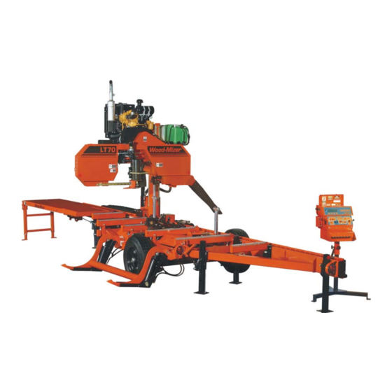
- Page 1 ® Wood-Mizer Sawmill Safety, Setup, Operation & Maintenance Manual LT70HD Remote rev. A3.01 - B3.01 Safety is our #1 concern! Read and understand all safety information and instructions before oper- ating, setting up or maintaining this machine. October 2004 Form #1190...
-
Page 2: Table Of Contents
Table of Contents Section-Page SECTION 1 INTRODUCTION About This Manual.................1-1 Getting Service ..................1-2 General Contact Information..........1-2 Branches & Authorized Sales Centers ........1-3 Specifications ..................1-5 Customer and Sawmill Identification.............1-7 SECTION 2 SAFETY Safety Symbols..................2-1 Safety Instructions ..................2-2 SECTION 3 SAWMILL SETUP Stationary Sawmill Setup ...............3-1 Portable Sawmill Setup ................3-15 Replacing The Blade ................3-30... - Page 3 Table of Contents Section-Page 5.11 Brake Adjustment (DC Only)...............5-19 5.12 Autoclutch Belt (DC Only) ..............5-20 5.13 Hydraulic System .................5-21 5.14 Up/Down System..................5-23 5.15 Power Feed ...................5-28 5.16 Charging The Battery (DC Only) ............5-31 5.17 Turner Chain Tension................5-33 5.18 Remote Cable Chain & Support Tray ..........5-34 SECTION 6 TROUBLESHOOTING GUIDE Sawing Problems ..................6-1...
- Page 4 Table of Contents Section-Page SECTION 7 SAWMILL ALIGNMENT Routine Alignment Procedure ..............7-1 Blade Installation..............7-1 Saw Head Tilt ..............7-2 Blade Guide Arm Alignment ..........7-4 Blade Guide Vertical Tilt Alignment........7-9 Blade Guide Horizontal Tilt Adjustment......7-11 Blade Guide Flange Spacing ..........7-13 Manual Side Support Alignment .........7-15 Hydraulic Side Support Alignment ........7-17 Blade Height Scale Adjustment...........7-18 Complete Alignment Procedure ............7-19...
-
Page 5: Introduction
The information and instructions given in this manual do not amend or extend the limited warranties for the equipment given at the time of purchase. For general information regarding Wood-Mizer and our “Forest to Final Form” products, please refer to the All Products Catalog in your support package. -
Page 6: Getting Service
Getting Service Getting Service Wood-Mizer is committed to providing you with the latest technology, best quality and strongest customer service available on the market today. We continually evaluate our customers’ needs to ensure we’re meeting current wood-processing demands. Your com- ments and suggestions are welcome. -
Page 7: Branches & Authorized Sales Centers
Wood-Mizer Canada Wood-Mizer Branches Authorized Sales Centers* Branches 2 Wood-Mizer Northeast 6 California 16 Wood-Mizer Canada East 8604 State Route 104 6980 Camp Far West Road Box 173, 1082 #1 Hwy Hannibal, NY 13074 Sheridan, CA 95681 Aylesford, NS B0P 1C0... - Page 8 Introduction Branches & Authorized Sales Centers 5 Wood-Mizer Missouri 9 Pennsylvania Authorized Sales Centers* 9664 Lawrence 2130 HCR 75 (Off Old Road 522) NMt. Vernon, MO 65712 Shade Gap, PA 17255 19 Ontario North Phone (417) 466-9500 Phone (814) 259-9976...
-
Page 9: Specifications
Introduction Specifications Specifications Model: LT70HD-R Rev. A5.00+ Dimensions: Length: 26'-2" Width: 6'-3" Height (Ground To Mast): 7'-5 1/2" Height (Max Head Position): 12'-0" Bed Height (Ground To Bed): 29" Blade Length: 184" Weights: Basic Unit (Wet): 5039 lbs 5079 lbs 4719 lbs 4486 lbs 4680 lbs... - Page 10 Introduction Specifications Model: LT70HD-R Rev. A1.00 - A4.01 Dimensions: Length: 26'-2" Width: 6'-3" Height (Ground To Mast): 7'-5 1/2" Height (Max Head Position): 12'-0" Bed Height (Ground To Bed): 29" Blade Length: 184" Weights: Basic Unit (Wet): 5039 lbs 5079 lbs 4719 lbs 4486 lbs w/Trailer: 5360 lbs...
-
Page 11: Customer And Sawmill Identification
Customer and Sawmill Identification Customer and Sawmill Identification Each Wood-Mizer sawmill has a model number and a 17-digit Vehicle Identification Num- ber (VIN). In addition, when you pick up your mill, you will receive a customer number. These three numbers will help expedite our service to you. Please locate them now and write them below so you have quick, easy access to them. - Page 12 Introduction Customer and Sawmill Identification The model number and V.I.N. can be found in the following locations. MODEL NUMBER AND V.I.N. LOCATIONS 60HD-R04doc112210 Introduction...
-
Page 13: Safety
Safety Safety Symbols SECTION 2 SAFETY Safety Symbols The following symbols and signal words call your attention to instructions concerning your personal safety. Be sure to observe and follow these instructions. DANGER! indicates an imminently hazardous situation which, if not avoided, will result in death or serious injury. WARNING! suggests a potentially hazardous situation which, if not avoided, could result in death or serious injury. -
Page 14: Safety Instructions
It is always the owner's responsibility to comply with all applicable federal, state and local laws, rules and regulations regarding the ownership, operation and towing of your Wood-Mizer sawmill. All Wood-Mizer mill owners are encouraged to become thoroughly familiar with these applicable laws and comply with them fully while using or towing the mill. - Page 15 Safety Safety Instructions WEAR SAFETY CLOTHING WARNING! Secure all loose clothing and jewelry before operating the sawmill. Failure to do so may result in serious injury or death. WARNING! Always wear gloves and eye protection when handling bandsaw blades. Changing blades is safest when done by one per- son! Keep all other persons away from area when coiling, carrying or changing a blade.
- Page 16 Failure to do so may result in serious injury. WARNING! Use ONLY water and Wood-Mizer Lube Additive with the water lube accessory. Never use flammable fuels or liquids such as diesel fuel. If these types of liquids are necessary to clean the blade, remove it and clean with a rag.
- Page 17 Safety Safety Instructions USE CAUTION WHEN WORKING WITH BATTERIES (GAS & DIESEL SAWMILLS ONLY) DANGER! Batteries expel explosive gases. Keep sparks, flames, burning cigarettes, or other ignition sources away at all times. Always wear safety goggles and a face shield when working near batteries.
- Page 18 Safety Safety Instructions CAUTIONS FOR SAWMILL SETUP WARNING! Do not set up the mill on ground with more than a 10 degree incline. If setup on an incline is necessary, put blocks under one side of the mill or dig out areas for the outrigger legs to keep mill level.
- Page 19 Safety Safety Instructions CHECK SAWMILL/BLADES BEFORE OPERATION DANGER! Make sure all guards and covers are in place and secured before operating or towing the sawmill. Failure to do so may result in serious injury. Be sure the blade housing and pulley covers are in place and secure.
- Page 20 Safety Safety Instructions KEEP PERSONS AWAY DANGER! Stay clear of the area between the trailer axle and saw carriage. Failure to do so will result in serious injury. DANGER! Keep all persons out of the path of moving equipment and logs when operating sawmill or loading and turning logs. Fail- ure to do so will result in serious injury.
- Page 21 Safety Safety Instructions KEEP HANDS AWAY DANGER! Always disengage the blade and shut off the sawmill engine before changing the blade. Failure to do so will result in serious injury. DANGER! Engine components can become very hot during opera- tion. Avoid contact with any part of a hot engine. The exhaust com- ponents of your engine are especially hot during and following operation.
- Page 22 Safety Safety Instructions CAUTIONS FOR GAS OR DIESEL ENGINE OPERATION DANGER! Operate your engine/machine only in well venti- lated areas. The exhaust gases of your engine can cause nausea, delirium and potentially death unless adequate ventilation is present. DANGER! Never operate an engine with a fuel or oil leak. The leaking fuel or oil could potentially come in contact with hot surfaces and ignite into flames.
- Page 23 Safety Safety Instructions USE PROPER PROCEDURE WHEN CONDUCTING ELECTRICAL SAFETY CHECKS AND MAINTENANCE DANGER! Make sure all electrical installation, service and/or maintenance work is performed by a qualified electrician and is in accordance with applicable electrical codes. DANGER! ARC FLASH AND SHOCK HAZARD! Hazardous volt- age inside the electric sawmill disconnect box, starter box, and at the motor can cause shock, burns, or death.
- Page 24 Safety Safety Instructions DANGER! Lockout procedures must be used during: Changing or adjusting blades Unjamming operations Cleaning Mechanical repair Electrical maintenance Retrieval of tools/parts from work area Activities where guards or electrical panel guard is open or removed Maintenance hazards include: Blade contact Pinch points Kickbacks...
- Page 25 Safety Safety Instructions SAWMILL LOCKOUT PROCEDURE Lockout procedures must be followed (see ANSI Standard Z244.1-1982 and OSHA regu- lation 1910.147). Purpose: This procedure establishes the minimum requirements for lockout of energy sources that could cause injury. Responsibility: The responsibility for seeing that this procedure is followed is binding upon all workers. All workers shall be instructed in the safety significance of the lockout procedure.
- Page 26 Owner’s Responsibility The procedures listed in this manual may not include all ANSI, OSHA, or locally required safety procedures. It is the owner/operator’s responsibility and not Wood-Mizer Products to ensure all operators are properly trained and informed of all safety protocols.
- Page 27 Safety Safety Instructions KEEP SAFETY LABELS IN GOOD CONDITION IMPORTANT! Always be sure that all safety decals are clean and readable. Replace all damaged safety decals to prevent personal injury or damage to the equipment. Contact your local distributor, or call your Customer Service Representative to order more decals.
- Page 28 Safety Safety Instructions UP/DOWN SYSTEM SAFETY WARNING! Always secure the saw head with a 5/16" chain with at least 1900 lbs. working load capacity before adjusting the up/down chain. The saw head may fall, causing severe injury or death. WARNING! Always secure the saw head with a 5/16"...
- Page 29 Safety Safety Instructions GENERAL TRAILER SAFETY DANGER! Make sure your hitch has adequate safety chain hook- ups. Do not use eyebolts for safety chain hook-up. Safety chains should be hooked to bumper of vehicle so that each chain would pull the trailer equally in the event the hitch became disengaged. Failure to do so may result in serious personal injury and/or severe machine damage.
- Page 30 Safety Safety Instructions ADDITIONAL SAFETY FOR ELECTRIC BRAKE TRAILERS DANGER! Make sure the electric brake wire is secured as close to the trailer axle as possible to prevent wire disconnection during towing. Failure to do so may result in serious personal injury and/or severe machine damage.
-
Page 31: Sawmill Setup
Sawmill Setup Stationary Sawmill Setup SECTION 3 SAWMILL SETUP Stationary Sawmill Setup Prepare a firm, level area where the sawmill can be anchored. There should be enough room around the sawmill for operators, sawdust removal, log loading and board removal. A cement pad with 5/8”... - Page 32 Sawmill Setup Stationary Sawmill Setup See Figure 3-1. Before moving the saw carriage, remove the cable chain support bracket. 1. Disengage the rubber strap holding the cable chain to the support bracket. 2. Loosen the handles and remove the support bracket from the sawmill track rail. 3.
- Page 33 Sawmill Setup Stationary Sawmill Setup Setup the control box prior to operating the sawmill. See Figure 3-2. Control Box Locking Handles 600098-5 Storage Bracket FIG. 3-2 4. Turn the locking handles holding the control box to the storage bracket counterclockwise to loosen.
- Page 34 Sawmill Setup Stationary Sawmill Setup See Figure 3-3. J2A to P2A J3A to P3A J1A to P1A Cable Storage 600084-2 FIG. 3-3 6. Unhook the carriage safety chain, located at the bottom of the vertical mast. 7. Start the engine to enable the battery-operated accessories (See Section 3.6).
- Page 35 Sawmill Setup Stationary Sawmill Setup See Figure 3-4. Pivot End Rail Side Support Bed Rail Stop Block 600099 FIG. 3-4 Sawmill Setup 60HD-R04doc112210...
- Page 36 Sawmill Setup Stationary Sawmill Setup Rev. A5.00+: Setup the board return table for operation. 1. First, remove three retaining pins to detach the long table assembly from the sawmill. See Figure 3-5. 600187-1 FIG. 3-5 60HD-R04doc112210 Sawmill Setup...
- Page 37 Sawmill Setup Stationary Sawmill Setup 2. Lift the long table assembly off the rest pin and slide toward the front of the mill. Rest the long table on the short bottom table so it is balanced. Replace the three retaining pins. 3.
- Page 38 Sawmill Setup Stationary Sawmill Setup 4. Pull the outrigger pins and lower the legs. See Figure 3-7. 600187-3 FIG. 3-7 60HD-R04doc112210 Sawmill Setup...
- Page 39 Sawmill Setup Stationary Sawmill Setup 5. Slide the long table until it rests in position, level with the short table assembly. 6. If necessary, adjust the outrigger legs up or down so the table is level. See Figure 3-8. 600187-4 FIG.
- Page 40 Sawmill Setup Stationary Sawmill Setup Rev. A3.01 - A4.01: Setup the board return table for operation. 1. First, remove three retaining pins to detach the long table assembly from the sawmill. See Figure 3-9. 600149-1 FIG. 3-9 3-10 60HD-R04doc112210 Sawmill Setup...
- Page 41 Sawmill Setup Stationary Sawmill Setup 2. Lift the long table assembly off the rest pin and slide toward the front of the mill. Rest the long table on the short bottom table so it is balanced. Replace the three retaining pins. 3.
- Page 42 Sawmill Setup Stationary Sawmill Setup 4. Remove the four leg pins and pivot the legs toward the ground. Replace the leg pins. WARNING! To avoid injury, keep hands away from area where legs pivot. See Figure 3-11. 600149-3 FIG. 3-11 3-12 60HD-R04doc112210 Sawmill Setup...
- Page 43 Sawmill Setup Stationary Sawmill Setup 5. Slide the long table until it rests in position, level with the short table assembly. 6. If necessary, remove the leg adjustment pins and adjust the legs up or down so the table is level. Replace the leg adjustment pins. See Figure 3-12.
- Page 44 Sawmill Setup Stationary Sawmill Setup 7. Slide the long table until it rests in position, level with the short table assembly. 8. If necessary, remove the leg adjustment pins and adjust the legs up or down so the table is level. Replace the leg adjustment pins. See Figure 3-13.
-
Page 45: Portable Sawmill Setup
Sawmill Setup Portable Sawmill Setup Portable Sawmill Setup WARNING! Do not set up the mill on ground with more than a 10 degree incline. If setup on an incline is necessary, put blocks under one side of the mill or dig out areas for outrig- ger legs to keep mill level. - Page 46 Sawmill Setup Portable Sawmill Setup 1. Unhitch the mill from the vehicle. 2. Lower and set the front three outriggers. To lower, use the provided jack handle to lift the weight from the locking pin. If necessary, rotate the locking pin counterclockwise so that the inner roll pin is free from the outrigger channel notch, then pull the locking pin out to release the outrigger.
- Page 47 Sawmill Setup Portable Sawmill Setup See Figure 3-15. For Fine Adjust Outriggers (FAOs), lower the outrigger as close to the ground as possible, then secure in place with the locking pin. Adjust the outrigger base so that it contacts the ground. To adjust, use the provided wrench to turn the height adjust- ment nut.
- Page 48 Sawmill Setup Portable Sawmill Setup storage bracket and secure the rubber strap in the bracket hole. Remove strap Loosen handles from cable chain and remove chain support Store chain support on bracket between first and second bed rails 3H0479 FIG. 3-16 3-18 60HD-R04doc112210 Sawmill Setup...
- Page 49 Sawmill Setup Portable Sawmill Setup Setup the control box prior to operating the sawmill. See Figure 3-17. Control Control Box Box Stand Locking Handles 600098-6 Storage Bracket FIG. 3-17 1. Turn the locking handles holding the control box to the storage bracket counterclockwise to loosen.
- Page 50 Sawmill Setup Portable Sawmill Setup See Figure 3-18. J2A to P2A J3A to P3A J1A to P1A Cable Storage 600084-2 FIG. 3-18 1. Unhook the carriage safety chain, located at the bottom of the vertical mast. 2. Start the engine to enable the battery-operated accessories (See Section 3.6).
- Page 51 Sawmill Setup Portable Sawmill Setup 5. Lower and set the remaining rear outriggers. Level the sawmill by adjusting the outriggers to raise or lower each end of the sawmill. Adjust all outriggers evenly to avoid twisting the mill frame by jacking one outrigger higher than the others. For FAO(s), fine tune the outrigger base height as necessary.
- Page 52 Sawmill Setup Portable Sawmill Setup Rev. A5.00+: Setup the board return table for operation. 1. First, remove three retaining pins to detach the long table assembly from the sawmill. See Figure 3-20. 600187-1 FIG. 3-20 3-22 60HD-R04doc112210 Sawmill Setup...
- Page 53 Sawmill Setup Portable Sawmill Setup 2. Lift the long table assembly off the rest pin and slide toward the front of the mill. Rest the long table on the short bottom table so it is balanced. Replace the three retaining pins. 3.
- Page 54 Sawmill Setup Portable Sawmill Setup 4. Pull the outrigger pins and lower the legs. See Figure 3-22. 600187-3 FIG. 3-22 3-24 60HD-R04doc112210 Sawmill Setup...
- Page 55 Sawmill Setup Portable Sawmill Setup 5. Slide the long table until it rests in position, level with the short table assembly. 6. If necessary, adjust the outrigger legs up or down so the table is level. See Figure 3-23. 600187-4 FIG.
- Page 56 Sawmill Setup Portable Sawmill Setup Rev. A3.01 - A4.01: Setup the board return table for operation. 1. First, remove three retaining pins to detach the long table assembly from the sawmill. See Figure 3-24. 600149-1 FIG. 3-24 3-26 60HD-R04doc112210 Sawmill Setup...
- Page 57 Sawmill Setup Portable Sawmill Setup 2. Lift the long table assembly off the rest pin and slide toward the front of the mill. Rest the long table on the short bottom table so it is balanced. Replace the three retaining pins. 3.
- Page 58 Sawmill Setup Portable Sawmill Setup 4. Remove the four leg pins and pivot the legs toward the ground. Replace the leg pins. WARNING! To avoid injury, keep hands away from area where legs pivot. See Figure 3-26. 600149-3 FIG. 3-26 3-28 60HD-R04doc112210 Sawmill Setup...
- Page 59 Sawmill Setup Portable Sawmill Setup 5. Slide the long table until it rests in position, level with the short table assembly. 6. If necessary, remove the leg adjustment pins and adjust the legs up or down so the table is level. Replace the leg adjustment pins. See Figure 3-27.
-
Page 60: Replacing The Blade
Sawmill Setup Replacing The Blade Replacing The Blade DANGER! Always disengage the blade and shut off the sawmill engine before changing the blade. Failure to do so will result in serious injury. WARNING! Always wear gloves and eye protection when handling bandsaw blades. -
Page 61: Tensioning The Blade
Sawmill Setup Tensioning The Blade Tensioning The Blade See Figure 3-28. Before tensioning the blade, check the air pressure gauge to see that the air tension system is properly charged. With the blade tension completely released and the air bag plate against the stop bolt, the gauge should read 58 psi for 1 1/4” blades or 78 psi for 1 1/2”... - Page 62 Sawmill Setup Tensioning The Blade tensioning the blade. Failure to do so may result in injury. Check that the air bag plate is approximately 1/8” from the stop plate (or bolt prior to Rev. A7.03). This should provide approximately 60 psi of blade tension for 1 1/4” blades or 80 psi for 1 1/2”...
- Page 63 Sawmill Setup Tensioning The Blade Rev. A3.01 - A5.02: To tension the blade, turn the tension handle clockwise until the air bag plate is approximtately 1/8” from the head of the stop bolt. This should provide approximately 60 psi of blade tension for 1 1/4” blades or 80 psi for 1 1/2” and wider blades.
-
Page 64: Tracking The Blade
Sawmill Setup Tracking The Blade Tracking The Blade 1. Make sure the blade housing covers are closed and all persons are clear of the open side of the saw head. 2. Start the engine (or motor). 3. Engage the blade, rotating the blade until the blade positions itself on the wheels. WARNING! Do not spin the blade wheels by hand. - Page 65 Sawmill Setup Tracking The Blade 5. Use the cant adjustment bolt to adjust where the blade travels on the blade wheels. See Figure 3-1. DETAIL Turn bolt clockwise to move blade out on wheel; counterclockwise to move blade in on wheel Cant Adjustment Bolt (See Detail)
-
Page 66: Starting The Engine (Or Motor)
Sawmill Setup Starting The Engine (or Motor) Starting The Engine (or Motor) See the appropriate manual supplied with your specific engine/motor configuration for starting and operating instructions. DANGER! Make sure all guards and covers are in place and secured before operating or towing the sawmill. Failure to do so may result in serious injury. -
Page 67: Board Return
Sawmill Setup Board Return Board Return WARNING! The automatic board return is intended to assist a second operator in removing boards quickly. Do not use the board return when operating the sawmill alone. Serious injury, death or damage to the equipment may result. - Page 68 Sawmill Setup Board Return See Figure 3-32. To bypass the board return feature, pin the board return arms in the storage position. FIG. 3-32 3-38 60HD-R04doc112210 Sawmill Setup...
-
Page 69: Sawmill Operation
Sawmill Operation Hydraulic Control Operation SECTION 4 SAWMILL OPERATION Hydraulic Control Operation AC sawmill: The hydraulic controls are operational when the key switch is on except when the saw carriage is moving forward. DC & 550-600V AC sawmill: The hydraulic control levers become operational when the contacts at the bottom of the carriage touch the power strip on the frame tube. - Page 70 Sawmill Operation Hydraulic Control Operation 1. Move the clamp out and down so it will not get in the way of logs being loaded onto the bed. Lower the clamp in/out lever to move the clamp out toward the loading side of the saw- mill.
-
Page 71: Loading, Turning And Clamping Logs
Sawmill Operation Loading, Turning And Clamping Logs Loading, Turning And Clamping Logs To Load Logs 1. Move the saw carriage to the front end of the frame. CAUTION! Before loading a log, be sure the cutting head is moved far enough forward so the log does not hit it. Failure to do so may result in machine damage. - Page 72 Sawmill Operation Loading, Turning And Clamping Logs To Turn Logs 1. Raise the turner lever to engage the log turner arm. Let the arm rise until it touches the log. 2. Raise the turner chain lever to rotate the log clockwise. Lower the lever to rotate the log counterclockwise.
-
Page 73: Up/Down Operation
Sawmill Operation Up/Down Operation Up/Down Operation This section describes operation of the up/down system with the standard controls. See the operation section of the Accuset manual for alternate instructions for operating the up/down system. 1. Install a blade, if needed, and check for correct blade tension. (See Section 3.3). -
Page 74: Blade Guide Arm Operation
Sawmill Operation Blade Guide Arm Operation Blade Guide Arm Operation 1. Look down the length of the log to see its maximum width. The outer blade guide should be adjusted to clear the widest section of the log by less than 1" (25.4 mm). 2. -
Page 75: Autoclutch Operation (Dc Only)
Sawmill Operation Autoclutch Operation (DC Only) Autoclutch Operation (DC Only) AC Models: The blade will engage when the key switch is turned to the ON (#1) position. DC Models: The sawmill is equipped with an automatic clutch mechanism that remotely engages/disengages the blade using a switch on the control box. -
Page 76: Power Feed Operation
Sawmill Operation Power Feed Operation Power Feed Operation See Figure 4-5. The power feed system moves the carriage forward and backward by using two switches on the control panel. Carriage Forward Carriage Reverse Forward Feed Rate 3H0280 FIG. 4-5 Carriage Feed Rate The carriage feed rate switch controls the speed at which the carriage travels forward. - Page 77 Sawmill Operation Power Feed Operation WARNING! Be sure the power feed switch is in the neutral position before turning the key switch to the on (#1) or accessory (#3) position. This prevents accidental carriage movement which may cause serious injury or death. Using The Power Feed 1.
-
Page 78: Cutting The Log
Cutting The Log Cutting The Log The following steps guide you through normal operation of the Wood-Mizer sawmill. 1. Once the log is placed where you want it and clamped firmly, move the saw head to posi- tion the blade close to the end of the log. - Page 79 Sawmill Operation Cutting The Log 9. Lower the toe boards, if they were used. Use the hydraulic levers to release the clamp and engage the log turner. Turn the log 90 or 180 degrees. Make sure the flat on the log is placed flat against side supports if turned 90 degrees.
-
Page 80: Edging
Sawmill Operation Edging Edging The following steps guide you through edging boards on the Wood-Mizer sawmill. 1. Raise the side supports to 1/2 the height of the flitches, or the boards that need to be edged. 2. Stack the flitches on edge against the side supports. -
Page 81: Optional Cutting Procedure
Sawmill Operation Optional Cutting Procedure Optional Cutting Procedure In order to achieve maximum production rates, it may be desirable to leave the blade engaged when returning the carriage. (Normal operation procedures recommend disen- gaging the blade before returning the carriage for maximum blade life and fuel economy.) DANGER! If leaving the blade engaged for maximum pro- duction rates, make sure the off-bearer stays out of the... -
Page 82: Blade Height Scale
Sawmill Operation Blade Height Scale 4.10 Blade Height Scale See Figure 4-6. The blade height scale is attached to the carriage head frame. It includes: a blade height indicator an inch scale a quarter scale Blade Height Indicator Quarter Scale Inch Scale 3H0893 FIG. - Page 83 Sawmill Operation Blade Height Scale The Quarter Scale See Table 4-1. Two quarter scales are provided with four sets of marks. Each set repre- sents a specific lumber thickness. Saw kerf and shrinkage allowance are included, but actual board thickness will vary slightly depending on blade thickness and tooth set. To choose which scale to use, determine what finished thickness you want to end up with.
-
Page 84: Water Lube Operation
15 seconds. This will clean the blade of sap buildup. Wipe the blade dry with a rag before storing or sharpening. For further lubrication benefits, add one 12oz. bottle of Wood-Mizer Lube Additive to 5 gallons of water. Wood-Mizer Lube Additive enables some previously impossible timbers to be cut by significantly reducing resin buildup on the blade. - Page 85 Sawmill Operation Water Lube Operation fuels or liquids such as diesel fuel. If these types of liquids are necessary to clean the blade, remove it and clean with a rag. Failure to do so can damage the equipment and may result in serious injury or death.
-
Page 86: Preparing The Sawmill For Towing
Sawmill Operation Preparing The Sawmill For Towing 4.12 Preparing The Sawmill For Towing The Wood-Mizer trailer package makes transporting your sawmill easy and convenient. To get your sawmill ready for towing, follow these instructions. CAUTION! If the weight of the sawmill exceeds 3,000 lbs (1361 Kg) for any reason, an auxiliary braking system (such as electric brakes) must be used. - Page 87 Sawmill Operation Preparing The Sawmill For Towing 2. Move the clamp all the way in toward the main bed frame tube. CAUTION! Move the hydraulic clamp and turner to provide maximum ground clearance before towing. Failure to do so may result in damage to the sawmill. 3.
- Page 88 Sawmill Operation Preparing The Sawmill For Towing 9. If necessary, adjust the stop located at the bottom of the mast so the saw head contacts the stop after it is lowered 3/4" (19mm) past where it contacts the rest pin. See Figure 4-10.
- Page 89 Sawmill Operation Preparing The Sawmill For Towing See Figure 4-11. Clamp support to rail with handles Secure chain to support with strap Install chain support to top track rail between first and second bed rails 3H0480 FIG. 4-11 14. Tighten the support handles and secure the chain to the support with the rubber strap. 15.
- Page 90 Sawmill Operation Preparing The Sawmill For Towing See Figure 4-12. FIG. 4-12 CAUTION! Check to be sure the saw head safety chain is secured before towing the sawmill. Failure to properly secure the saw head can result in severe machine damage. Be sure the blade housing and pulley covers are in place and secure.
- Page 91 Sawmill Operation Preparing The Sawmill For Towing ting. CAUTION! Do not adjust the FAO outrigger base height while there is weight on the FAO. Damage to the FAO may result. See the trailer operator’s manual for specific information regarding hitch operation and towing the sawmill.
-
Page 92: Maintenance
Wear Life SECTION 5 MAINTENANCE This section lists the maintenance procedures that need to be performed. See the Maintenance Log located after this section for a complete list of maintenance procedures and intervals. Keep track of machine maintenance by filling in the machine hours and the date you perform each procedure. -
Page 93: Blade Guides
Maintenance Blade Guides Blade Guides WARNING! Before performing service near moving parts such as blades, pulleys, motors, belts and chains, first turn the key switch to the OFF (#0) position and remove the key. If the key is turned on and moving parts activated, serious injury may result. - Page 94 Maintenance Blade Guides See Figure 5-1. To adjust the top block down, loosen the clamp bolt and mounting bolt. Turn the adjust- ment bolt clockwise. Retighten the mounting bolt and clamp bolt. To adjust the bottom block up, loosen the clamp bolt and mounting bolt. Use the provided adjustment tool to turn the adjustment screw clockwise.
- Page 95 Maintenance Blade Guides 600214-5 Turn adjustment bolt clockwise to lower top block Loosen mounting bolt and clamp bolt Loosen mounting bolt and clamp bolt Use bottom block adjustment tool to raise bottom block FIG. 5-1 REV. A7.02 - A8.00 600122-14B Loosen mounting bolt and clamp bolt Turn adjustment bolt...
- Page 96 Maintenance Blade Guides guide system. If the wood you are sawing leaves sap buildup using plain water in the blade lube system, use Wood-Mizer lube additive (4-Pak 60 oz. bottles part no. ADD-1). 60HD-R04doc112210 Maintenance...
- Page 97 Maintenance Blade Guides 4. Make sure the blade screw in the top center of the C-frame is 1/16" (1.5 mm) away from the blade. If not, loosen the nut and adjust the screw as necessary. Check the screw every 500 hours of operation. Failing to maintain this adjustment will lead to early blade breakage.
-
Page 98: Sawdust Removal
Maintenance Sawdust Removal Sawdust Removal WARNING! Before performing service near moving parts such as blades, pulleys, motors, belts and chains, first turn the key switch to the OFF (#0) position and remove the key. If the key is turned on and moving parts activated, serious injury may result. -
Page 99: Carriage Track, Wiper & Scrapers
Maintenance Carriage Track, Wiper & Scrapers Carriage Track, Wiper & Scrapers WARNING! Before performing service near moving parts such as blades, pulleys, motors, belts and chains, first turn the key switch to the OFF (#0) position and remove the key. If the key is turned on and moving parts activated, serious injury may result. - Page 100 Maintenance Carriage Track, Wiper & Scrapers 3. Check the track scrapers as needed. Make sure the scrapers fit firmly against the rail. If a track scraper needs to be adjusted, loosen the screw, push the scraper downward until it fits firmly against the rail, and retighten the screw. Clean and lubricate track wiper...
-
Page 101: Vertical Mast Rails
Maintenance Vertical Mast Rails Vertical Mast Rails WARNING! Before performing service near moving parts such as blades, pulleys, motors, belts and chains, first turn the key switch to the OFF (#0) position and remove the key. If the key is turned on and moving parts activated, serious injury may result. -
Page 102: Drum Switches
Lubricate the up/down and power feed drum switch contacts inside the control panel every fifty hours of operation. Use only contact grease supplied by Wood-Mizer. Remove the control panel cover. Use a cotton swab to apply grease to the switch contact ends. -
Page 103: Miscellaneous
Maintenance Miscellaneous Miscellaneous WARNING! Before performing service near moving parts such as blades, pulleys, motors, belts and chains, first turn the key switch to the OFF (#0) position and remove the key. If the key is turned on and moving parts activated, serious injury may result. -
Page 104: Blade Tensioner
Maintenance Blade Tensioner Blade Tensioner WARNING! Before performing service near moving parts such as blades, pulleys, motors, belts and chains, first turn the key switch to the OFF (#0) position and remove the key. If the key is turned on and moving parts activated, serious injury may result. - Page 105 Maintenance Blade Tensioner Rev. A3.01 - A8.01: 1. Rev. A5.03 - A8.01 only: Lubricate the moving parts of the tensioner cam system with a heavy duty teflon spray lubricant, such as Gunk L508, every fifty hours of operation. 2. Lubricate the tensioner screw handle with a NLGI No. 2 grade lithium grease as needed. See Figure 5-6.
-
Page 106: Blade Wheel Belts
Maintenance Blade Wheel Belts Blade Wheel Belts WARNING! Before performing service near moving parts such as blades, pulleys, motors, belts and chains, first turn the key switch to the OFF (#0) position and remove the key. If the key is turned on and moving parts activated, serious injury may result. -
Page 107: Drive Belt Adjustment
Maintenance Drive Belt Adjustment 5.10 Drive Belt Adjustment WARNING! Disconnect and lockout power before perform- ing any service to the electrical system. For battery-pow- ered equipment, disconnect the negative battery terminal cable. For AC-powered equipment, follow the lockout pro- cedure provided in the safety section (See Section 2.2). - Page 108 Maintenance Drive Belt Adjustment Rev. A3.01 - A7.06: NOTE: A retrofit is available for the belt tensioning system (Part No. 038934). Modified pivot brackets increase the range of motion to reduce strain on gearbox. If the system has been retrofitted, the grooves in the belt tensioner link arm will no longer be used to indicate proper belt tension.
- Page 109 Maintenance Drive Belt Adjustment 4. Replace the key and turn the key switch to the accessory (#3) position. Turn the blade switch off and back on and recheck the belt tension. Repeat adjustments as necessary until proper belt tension is achieved when the belt is engaged. 5.
-
Page 110: Brake Adjustment (Dc Only)
Maintenance Brake Adjustment (DC Only) 5.11 Brake Adjustment (DC Only) WARNING! Before performing service near moving parts such as blades, pulleys, motors, belts and chains, first turn the key switch to the OFF (#0) position and remove the key. If the key is turned on and moving parts activated, serious injury may result. -
Page 111: Autoclutch Belt (Dc Only)
Tighten the belt to 1/16” deflec- tion with 1/4 lb. deflection force. Wood-Mizer offers a belt tension gauge (Part No. 016309) that will let you accurately measure the belt tension. -
Page 112: Hydraulic System
Maintenance Hydraulic System 5.13 Hydraulic System WARNING! Disconnect and lockout power before perform- ing any service to the electrical system. For battery-pow- ered equipment, disconnect the negative battery terminal cable. For AC-powered equipment, follow the lockout pro- cedure provided in the safety section (See Section 2.2). - Page 113 Maintenance Hydraulic System 2. Replace the hydraulic system cartridge filter every 500 hours of operation. 3. DC Only: Inspect the hydraulic pump motor brushes every 750 hours of operation. Remove brush dust and replace the brushes if they worn to a length of 1/4” or shorter. CAUTION! Do not operate the hydraulic system if the pump motor brushes are worn shorter than 1/4”.
-
Page 114: Up/Down System
Maintenance Up/Down System 5.14 Up/Down System WARNING! Before performing service near moving parts such as blades, pulleys, motors, belts and chains, first turn the key switch to the OFF (#0) position and remove the key. If the key is turned on and moving parts activated, serious injury may result. - Page 115 Drain and refill the gearbox with 40 ounces of oil after every 5000 hours of sawmill opera- tion or every 2 years, whichever comes first. Wood-Mizer offers replacement gear oil in 8 ounce bottles. 7. Inspect the up/down motor brushes every 750 hours of operation. Remove brush dust and replace the brushes if they worn to a length of 5/8”...
- Page 116 Maintenance Up/Down System Rev. A5.00 - B3.01: The up/down system is equipped with a gas spring assist mecha- nism to provide improved speed and performance. The saw head must be secured and tension released from the assist assembly before performing any maintenance to assist components.
- Page 117 Maintenance Up/Down System See Figure 5-14. 600188B Loosen Lower Mounting Bolts (4) Turn Tension Bolt Counterclockwise to Remove Tension FIG. 5-14 4. Loosen (do NOT remove) the four lower mounting bolts to allow the bracket to move along the slotted mounting holes. 5.
- Page 118 Maintenance Up/Down System ing down into the tube. Secure chain at top of assist assembly Remove remaining two upper mounting bolts FIG. 5-15 7. Remove the two remaining upper mounting bolts at the top of the assist assembly and lift the assembly from the mast tube.
-
Page 119: Power Feed
Maintenance Power Feed 5.15 Power Feed WARNING! Before performing service near moving parts such as blades, pulleys, motors, belts and chains, first turn the key switch to the OFF (#0) position and remove the key. If the key is turned on and moving parts activated, serious injury may result. - Page 120 Maintenance Power Feed See Figure 5-16. Adjustment Nut Chain Tensioner 600012 FIG. 5-16 5-29 60HD-R04doc112210 Maintenance...
- Page 121 Drain and refill the gearbox with 12 - 15 ounces of oil after every 5000 hours of sawmill operation or every 2 years, whichever comes first. Wood-Mizer offers replacement gear oil in 8 ounce bottles. Maintenance 60HD-R04doc112210 5-30...
-
Page 122: Charging The Battery (Dc Only)
Maintenance Charging The Battery (DC Only) 5.16 Charging The Battery (DC Only) DANGER! Batteries expel explosive gases. Keep sparks, flames, burning cigarettes, or other ignition sources away at all times. Always wear safety goggles and a face shield when working near batteries. Failure to do so will cause serious injury. - Page 123 Maintenance Charging The Battery (DC Only) CAUTION! Be sure the battery is fully charged before transporting the sawmill. If the battery is not fully charged, excessive vibration could reduce the overall service life of the battery. NOTE: A fuse terminal extension stud is provided in the fuse box.
-
Page 124: Turner Chain Tension
Maintenance Turner Chain Tension 5.17 Turner Chain Tension WARNING! Before performing service near moving parts such as blades, pulleys, motors, belts and chains, first turn the key switch to the OFF (#0) position and remove the key. If the key is turned on and moving parts activated, serious injury may result. -
Page 125: Remote Cable Chain & Support Tray
Maintenance Remote Cable Chain & Support Tray 5.18 Remote Cable Chain & Support Tray WARNING! Before performing service near moving parts such as blades, pulleys, motors, belts and chains, first turn the key switch to the OFF (#0) position and remove the key. If the key is turned on and moving parts activated, serious injury may result. - Page 126 Maintenance Remote Cable Chain & Support Tray 1. The chain should travel in a straight line. Traveling at an angle will cause the chain to pre- maturely wear and break. Check the alignment of the chain by measuring from the saw- mill frame tube to the center of the chain at the top and bottom.
- Page 127 Maintenance Remote Cable Chain & Support Tray 2. The chain support tray must be level to prevent premature wear of the chain. Use a square to check the angle of the tray to the sawmill frame. Check at several locations along the length of the tray.
- Page 128 MAINTENANCE LOG (Check Engine And Option Manuals For Additional Maintenance Procedures) Check Blade Guide Block/Roller Wear See Section 5.2 Daily - Every Blade Change Remove Excess Sawdust From Blade Wheel Hous- See Section 5.3 Daily - Every Blade Change DAILY MAINTENANCE PROCEDURES ings And Sawdust Chute Inspect Fingers Inside Sawdust Chute See Section 5.3...
- Page 129 MAINTENANCE LOG (Check Engine And Option Manuals For Additional Maintenance Procedures) TOTAL HOURS OF OPERATION MANUAL FILL IN THE DATE AND THE MACHINE HOURS AS YOU PERFORM EACH PROCEDURE. PROCEDURE REFERENCE A SHADED BOX INDICATES MAINTENANCE IS NOT NEEDED AT THIS TIME. 550 HRS 600 HRS 650 HRS...
- Page 130 MAINTENANCE LOG (Check Engine And Option Manuals For Additional Maintenance Procedures) TOTAL HOURS OF OPERATION MANUAL FILL IN THE DATE AND THE MACHINE HOURS AS YOU PERFORM EACH PROCEDURE. PROCEDURE REFERENCE A SHADED BOX INDICATES MAINTENANCE IS NOT NEEDED AT THIS TIME. 1050 HRS 1100 HRS 1150 HRS...
- Page 131 MAINTENANCE LOG (Check Engine And Option Manuals For Additional Maintenance Procedures) TOTAL HOURS OF OPERATION MANUAL FILL IN THE DATE AND THE MACHINE HOURS AS YOU PERFORM EACH PROCEDURE. PROCEDURE REFERENCE A SHADED BOX INDICATES MAINTENANCE IS NOT NEEDED AT THIS TIME. 1550 HRS 1600 HRS 1650 HRS...
- Page 132 MAINTENANCE LOG (Check Engine And Option Manuals For Additional Maintenance Procedures) TOTAL HOURS OF OPERATION MANUAL FILL IN THE DATE AND THE MACHINE HOURS AS YOU PERFORM EACH PROCEDURE. PROCEDURE REFERENCE A SHADED BOX INDICATES MAINTENANCE IS NOT NEEDED AT THIS TIME. 2050 HRS 2100 HRS 2150 HRS...
- Page 133 MAINTENANCE LOG (Check Engine And Option Manuals For Additional Maintenance Procedures) TOTAL HOURS OF OPERATION MANUAL FILL IN THE DATE AND THE MACHINE HOURS AS YOU PERFORM EACH PROCEDURE. PROCEDURE REFERENCE A SHADED BOX INDICATES MAINTENANCE IS NOT NEEDED AT THIS TIME. 2550 HRS 2600 HRS 2650 HRS...
-
Page 134: Troubleshooting Guide
Troubleshooting Guide Sawing Problems SECTION 6 TROUBLESHOOTING GUIDE Sawing Problems WARNING! Before performing service near moving parts such as blades, pulleys, motors, belts and chains, first turn the key switch to the OFF (#0) position and remove the key. If the key is turned on and moving parts activated, serious injury may result. - Page 135 Troubleshooting Guide Sawing Problems PROBLEM CAUSE SOLUTION Boards Thick Or Thin On Stress in log which causes log After log has been squared, take Ends Or Middle Of Board. to not lay flat on the bed. equal cuts off opposing sides. Take a board off the top.
-
Page 136: Electrical Problems
Switches Remain Engaged switch. up/down switch back to neutral or "off" When Switch Is Released. position. Replace drum switch or remove control panel cover and clean and lubri- cate contacts NOTE: Use only contact grease supplied by Wood-Mizer. 60HD-R04doc112210 Troubleshooting Guide... - Page 137 Troubleshooting Guide Electrical Problems Drum switch spring broken. Manually move the power feed or up/down switch back to neutral or "off" position. Replace drum switch spring. Troubleshooting Guide 60HD-R04doc112210...
- Page 138 Troubleshooting Guide Electrical Problems PROBLEM CAUSE SOLUTION Up/Down Or Power Feed System overload or bind Correct problem (See Section 6.4 Motors Overheat And Lose occurred. Allow motor to cool before restarting. Power. Normal operation factors Allow motor to cool before restarting. exceeded (eg: up/down con- trol jockeyed excessively).
-
Page 139: Power Feed Problems
Drum switch is dirty. Clean drum switch and lubricate Speeds Or Does Not Move with contact grease supplied by Until Speed Is Above Halfway Wood-Mizer. Mark. Drum switch contacts are bad Check that contacts are in good condition and positively close cir- cuit. - Page 140 Troubleshooting Guide Power Feed Problems PROBLEM CAUSE SOLUTION Power Feed Motor Overheats. Middle track oiler is dragging. Clean middle track oiler and lubricate with 30-weight oil or ATF (Automatic Transmission Fluid) such as Dexron II. Allow motor to cool before restarting. Ground is not level.
-
Page 141: Power Feed Circuit Troubleshooting
Troubleshooting Guide Power Feed Circuit Troubleshooting Power Feed Circuit Troubleshooting LT70HD Remote Rev. A4.00 - B2.00 NOTE: The power feed motor is controlled by the dual-axis Accuset 2 control module, eliminating the power feed circuit board (Rev. B3.00). See Accuset 2 option manual troubleshooting instructions. - Page 142 Troubleshooting Guide Power Feed Circuit Troubleshooting See Table 6-1. The drum switch positions and light states with the feed rate dial switch all the way up are shown below. Power Feed Drum Switch Position FORWARD REVERSE NEUTRAL TABLE 6-1 Please contact Customer Service for assistance if necessary when troubleshooting the system using these lights.
- Page 143 Troubleshooting Guide Power Feed Circuit Troubleshooting The LED Bar Graph located on the power feed board can also be used to troubleshoot feed problems. Check below for different codes on the LED Bar Graph to find the prob- lem. See Figure 6-2. The operational codes of the LED Bar Graph are shown below. SM0314-2B Key On, Bridge Enabled, Power Feed Drum Switch in Forward Position, Power Feed Potentiometer Off, No Faults...
-
Page 144: Lt60Hd/70Hd Remoterev. A3.01 - A3.03
Troubleshooting Guide Power Feed Circuit Troubleshooting LT60HD/70HD Remote Rev. A3.01 - A3.03 LED lights are provided on the control module to help troubleshoot any feed problems you may encounter. See Figure 6-4. The lights can be viewed by opening the remote junction box door. DETAIL Detail 3H0470B-3... - Page 145 Troubleshooting Guide Power Feed Circuit Troubleshooting PWR - Indicates battery power is present at the power feed control circuit board. Troubleshooting Guide 60HD-R04doc112210 6-12...
-
Page 146: Hydraulic Problems
See Monarch manual for noid. Tapping on solenoid may fix tem- troubleshooting solenoid porarily. Replace solenoid if necessary. NOTE: The solenoid is not a standard automotive type. Order from Wood-Mizer only 6-13 60HD-R04doc112210 Troubleshooting Guide... - Page 147 Troubleshooting Guide Hydraulic Problems Defective pump motor Remove motor from pump and inspect. Repair or replace as necessary Troubleshooting Guide 60HD-R04doc112210 6-14...
- Page 148 Troubleshooting Guide Hydraulic Problems PROBLEM CAUSE SOLUTION You Can Get Response From Valve assembly switch con- Locate the valve switch at the bottom the Pump By Actuating All tacts are not properly of the valve assembly. Use a 3MM But One or Two Handles adjusted allen wrench to loosen the set screw on each of the five switch contacts.
- Page 149 Troubleshooting Guide Hydraulic Problems PROBLEM CAUSE SOLUTION Hydraulic Side Supports Go Dirt in sequence valve Remove sequence valves and clean Down Before Or At Same thoroughly with kerosene. NOTE: Be Time As Log Turner sure to reassemble the valve and install it in its original position on the cylinder Retainer in sequence valve...
- Page 150 Troubleshooting Guide Hydraulic Problems PROBLEM CAUSE SOLUTION Hydraulic Toe Boards Can be a result of shock load INITIAL CHECK "Creep" UP without the caused by improperly using To check, disconnect the toe board valve control handles being the toe boards to "cushion" hydraulic hose from its current valve operated.
- Page 151 Troubleshooting Guide Hydraulic Problems PROBLEM CAUSE SOLUTION Hydraulic Toe Boards or Can be a result of shock load INITIAL CHECK Clamp "Creep" DOWN with- caused by improperly using To check, disconnect the toe board out the valve control han- the toe boards or clamp to hydraulic hose from its current valve dles being operated OR do "cushion"...
- Page 152 Troubleshooting Guide Hydraulic Problems PROBLEM CAUSE SOLUTION Pump runs but makes Low fluid level Check fluid level and add fluid as nec- “growling” sound and essary. Check for leaks in the system hydraulic functions are slow, at the control box fittings, hoses and jerky or don’t work at all.
-
Page 153: Engine/Motor And Drive Pulleys Alignment
Troubleshooting Guide Engine/Motor and Drive Pulleys Alignment Engine/Motor and Drive Pulleys Alignment WARNING! Before performing service near moving parts such as blades, pulleys, motors, belts and chains, first turn the key switch to the OFF (#0) position and remove the key. If the key is turned on and moving parts activated, serious injury may result. -
Page 154: Power Feed Variable Feed Rate Switch Test
Troubleshooting Guide Power Feed Variable Feed Rate Switch Test Power Feed Variable Feed Rate Switch Test With the feed rate dial switch all the way down, move the shaft of the dial back and forth to see if there is a jerky response. Turn the dial and move the shaft back and forth again. Repeat several times. -
Page 155: Power Feed Mechanical Test
Troubleshooting Guide Power Feed Mechanical Test Power Feed Mechanical Test 1. Remove the weight from the track rollers. They should turn smoothly and easily with very little play. 2. Make sure the middle track cover is not bent or touching the top rail. 3. -
Page 156: Hydraulic Pressure Test
Troubleshooting Guide Hydraulic Pressure Test Hydraulic Pressure Test To check hydraulic pressure: See Figure 6-5. Relief Valve Adjustment Screw Hydraulic Pressure 600200-2 Gauge FIG. 6-5 Operate the loading arm hydraulic lever and read the pressure on the gauge. Hydraulic pressure is factory-set at 2200 psi and should not need to be readjusted. The relief valve adjustment screw shown may be used to fine-tune the hydraulic pressure: Remove the adjustment screw nut. -
Page 157: Fuse Terminal Extension Stud
Troubleshooting Guide Fuse Terminal Extension Stud 6.10 Fuse Terminal Extension Stud LT70HD Remote Rev. A3.01 - B2.00 A fuse terminal extension stud is provided in the fuse box. The extension may be used to temporarily connect a battery charger or jumper cables to raise the saw head from the towing position so the battery box lid can be removed. - Page 158 Troubleshooting Guide LT70HD Remote Rev. A3.01 - B2.00 3. Attach the positive cable from a battery charger or jumper cables to the extension stud. 4. Connect the negative cable from the charger or jumper cables to a grounded metal sur- face.
-
Page 159: Circuit Breaker Operation
Troubleshooting Guide Circuit Breaker Operation 6.11 Circuit Breaker Operation Sawmill controls are equipped with manual reset circuit breakers to protect the electrical circuits. See Figure 6-7. DC Models Only Rev. B3.00 - B3.01+: The power feed, up/down, key- switch and autoclutch breakers are externally mounted at the side of the remote junction box. - Page 160 Troubleshooting Guide Circuit Breaker Operation See Figure 6-8. DC Models Only Prior to Rev. B3.00: The power feed, up/down, and autoclutch breakers are externally mounted at the side of the remote junction box. A key- switch breaker is located inside the remote junction box. Up/Down Power Feed Autoclutch...
- Page 161 Troubleshooting Guide Circuit Breaker Operation See Figure 6-9. The blade guide, accessory, ignition and start breakers are located inside the control box. Remove the circuit breaker panel from the control box to access the internal breakers. NOTE: If the breaker is still hot, you may not be able to reset it immediately.
- Page 162 Troubleshooting Guide Circuit Breaker Operation See Figure 6-10. AC Models Only: The hydraulic, ignition, start and blade guide break- ers are located inside the control box. Remove the circuit breaker panel from the control box to acess the internal breakers. Internal Circuit Breakers (Remove Panel) Blade Guide Ignition...
-
Page 163: Sawmill Alignment
Routine Alignment Procedure SECTION 7 SAWMILL ALIGNMENT The Wood-Mizer sawmill is factory aligned. Two alignment procedures are available to realign the sawmill if necessary. The Routine Alignment instructions should be performed as necessary to solve sawing problems not related to blade performance. The Complete Alignment procedure should be performed approximately every 1500 hours of operation (sooner if you regularly transport the sawmill over rough terrain). -
Page 164: Saw Head Tilt
Sawmill Alignment Routine Alignment Procedure Saw Head Tilt As the blade enters a wide log or cant, the outside of the saw head will drop down slightly. To compensate for the drop, the saw head is adjusted 1/16" (1.5 mm) higher at the out- side. - Page 165 Sawmill Alignment Routine Alignment Procedure See Figure 7-2. To adjust the saw head tilt, use the bolts located at the bottom of the saw head mast. Loosen the three sets of four retaining plate bolts. To raise the outside of the saw head, back the stop bolts out, then tighten the adjustment bolts.
-
Page 166: Blade Guide Arm Alignment
Sawmill Alignment Routine Alignment Procedure Blade Guide Arm Alignment The blade guide arm moves the outer blade guide in and out. If the arm becomes loose, the blade guide will not deflect the blade properly, causing inaccurate cuts. A loose blade guide arm can also cause blade vibration. - Page 167 Sawmill Alignment Routine Alignment Procedure After tightening the blade guide arm rollers, check that the arm is aligned properly. 3. With the arm adjusted 1/2" (15 mm) from fully closed, measure the distance between the blade guide roller flange and the back of the blade. See Figure 7-4.
- Page 168 Sawmill Alignment Routine Alignment Procedure See Figure 7-5. Loosen the horizontal adjustment bolt jam nuts. To tilt the arm in toward the blade, loosen the rear bolt and tighten the front bolt. To tilt the arm out away from the blade, loosen the front bolt and tighten the rear bolt.
- Page 169 Sawmill Alignment Routine Alignment Procedure See Figure 7-6. Measure from blade guide arm to bed rail with arm open and closed 600025-2 FIG. 7-6 7. Adjust the blade guide arm to 1/2" (15 mm) from fully open. Measure the distance from the bottom of the blade guide mounting block to the bed rail.
- Page 170 Sawmill Alignment Routine Alignment Procedure See Figure 7-7. Loosen the vertical adjustment bolt jam nuts. To tilt the blade guide arm down, loosen the rear bolt and tighten the front bolt. To tilt the blade guide arm up, loosen the front bolt and tighten the rear bolt. Retighten the jam nuts and recheck the blade guide arm vertical tilt.
-
Page 171: Blade Guide Vertical Tilt Alignment
Sawmill Alignment Routine Alignment Procedure Blade Guide Vertical Tilt Alignment The blade guides should be adjusted properly in the vertical plane. If the blade guides are tilted vertically, the blade will try to travel in the tilted direction. A Blade Guide Alignment Tool (BGAT) is provided to help you measure the vertical tilt of the blade. - Page 172 Sawmill Alignment Routine Alignment Procedure See Figure 7-9. Loosen the jam nuts on the top and bottom vertical tilt adjustment screws. To tilt the roller up, loosen the bottom screw and tighten top screw. To tilt the roller down, loosen the top screw and tighten the bottom screw. Tighten the jam nuts and recheck the tilt of the blade.
-
Page 173: Blade Guide Horizontal Tilt Adjustment
Sawmill Alignment Routine Alignment Procedure Blade Guide Horizontal Tilt Adjustment If the blade guides are tilted in the wrong direction horizontally, the back of the blade may contact the flange as the roller is spinning down, causing it to push the blade away from the guide roller. - Page 174 Sawmill Alignment Routine Alignment Procedure See Figure 7-11. Loosen the jam nuts on the horizontal tilt adjustment screws. To tilt the roller left, loosen the right screw and tighten left screw. To tilt the roller right, loosen the left screw and tighten the right screw. Tighten the jam nuts and recheck the tilt of the blade.
-
Page 175: Blade Guide Flange Spacing
Sawmill Alignment Routine Alignment Procedure Blade Guide Flange Spacing Each blade guide must be adjusted so the roller flange is the correct distance from the back edge of the blade. If the flange is too close to or too far from the blade, the sawmill will not cut accurately. - Page 176 Sawmill Alignment Routine Alignment Procedure Stop Bolt Loosen top and 600122-12B one side adjustment screw 1/16” (Inner Blade Guide) 1/8” (Outer Blade Guide) FIG. 7-12 REV. A3.01 - A7.01 2. Measure the distance between the flange on the inner blade guide roller to the back edge of the blade.
-
Page 177: Manual Side Support Alignment
Sawmill Alignment Routine Alignment Procedure Manual Side Support Alignment Logs and boards are clamped against the side supports when sawing. The sides supports must be square to the bed to ensure square lumber. 1. Swing a side support down and measure between the face of the support and the main bed tube. - Page 178 Sawmill Alignment Routine Alignment Procedure See Figure 7-14. Loosen the side support mounting bolt. Use a 3/8" ratchet to rotate the pin until the side support is square to the bed. Alignment Tubes (2) Place square against side support Loosen mounting bolt SM0272-1 Use 3/8”...
-
Page 179: Hydraulic Side Support Alignment
Sawmill Alignment Routine Alignment Procedure Hydraulic Side Support Alignment Place the square against the face of the side support. The side support should be square or slightly tilted forward 1/32" (0.8 mm). Adjust the vertical tilt of the side support if neces- sary. -
Page 180: Blade Height Scale Adjustment
Sawmill Alignment Routine Alignment Procedure Blade Height Scale Adjustment After the entire sawmill has been aligned and all adjustments made, check that the blade height scale indicates the true distance from the blade to the bed rails. 1. Move the saw carriage so the blade is positioned directly above one of the bed rails. Mea- sure from the bottom edge on a down-set tooth of the blade to the top of the bed rail, near the inner blade guide assembly. -
Page 181: Complete Alignment Procedure
LT60HD Remote: Adjust the two outriggers on the main frame tube down just enough to lift weight from the trailer tire. LT70HD Remote: Adjust the front and third outriggers on the main frame tube down just enough to lift weight from the trailer tire. -
Page 182: Blade Installation
Sawmill Alignment Complete Alignment Procedure Blade Installation 1. Remove the blade and replace the blade wheel belts. New blade wheel belts are required to perform the complete alignment procedure. 2. Blow sawdust off of the blade guide assemblies. Remove sawdust from the blade hous- ings. -
Page 183: Blade Wheel Alignment
Sawmill Alignment Complete Alignment Procedure Blade Wheel Alignment The blade wheels should be adjusted so they are level in the vertical and horizontal planes. If the blade wheels are tilted up or down, the blade will want to travel in the tilted direction. - Page 184 Sawmill Alignment Complete Alignment Procedure 600025-4B Adjust vertical adjustment screws up to tilt drive-side blade wheel down; Adjust screws down to tilt wheel up FIG. 7-18 5. Recheck the vertical tilt of the drive-side blade wheel with the blade guide alignment tool. Readjust the blade wheel as necessary until the front and rear of the tool are the same distance from the bed rail (within 1/16"...
- Page 185 Sawmill Alignment Complete Alignment Procedure 600025-5 Adjust vertical adjustment screws up to tilt idle-side blade wheel down; Adjust screws down to tilt wheel up FIG. 7-19 8. Recheck the vertical tilt of the idle-side blade wheel with the blade guide alignment tool. Readjust the blade wheel as necessary until the front and rear of the tool are the same distance from the bed rail (within 1/16"...
- Page 186 Sawmill Alignment Complete Alignment Procedure 9. Check the position of the blade on the idle-side blade wheel. See Figure 7-20. The horizontal tilt of the blade wheel should be adjusted so that the gul- let of an 1-1/4" blade is 1/8" (3 mm) out from the front edge of the wheel (±1/16 [1.5 mm]).The gullet of an 1-1/2"...
- Page 187 Sawmill Alignment Complete Alignment Procedure 10. Check the position of the blade on the drive-side blade wheel. The blade should be posi- tioned on the wheel as described for the idle-side blade wheel. Adjust the drive-side blade wheel if necessary. See Figure 7-22.
-
Page 188: Track Roller Adjustment
Sawmill Alignment Complete Alignment Procedure Track Roller Adjustment Making these adjustments correctly will insure the saw carriage travels smoothly along the track and blade will remain parallel with the bed frame. 1. Using the feed controls, move the saw carriage so that the blade is positioned over the front pivot end rail. - Page 189 Sawmill Alignment Complete Alignment Procedure 3. Open the adjustable blade guide arm to within 1/2" (15 mm) of full open. 4. Move the carriage back to the front pivot end rail. Raise the cutting head until the bottom of the blade is 17" (400 mm) above the outside of the pivot rail support by actual mea- surement with a tape or ruler.
- Page 190 Sawmill Alignment Complete Alignment Procedure saw head tilt and readjust the bolts as necessary. Retighten the retaining plate bolts. Stop Bolt Retaining Adjustment Bolt Plate Bolts 600011-4B Tighten adjustment bolts to raise saw head; Stop Bolt Loosen adjustment Adjustment Bolt bolts to lower saw head DETAIL OF LOWER TRACK ROLLER ASSEMBLY FIG.
-
Page 191: Bed Rail Adjustment
Sawmill Alignment Complete Alignment Procedure Bed Rail Adjustment 1. Move the clamp so it is 10" from the clamp stop. Adjust the clamp down to its lowest pos- tion. Move the saw head forward until it is positioned over the clamp. Raise the saw head until the blade measures 15 5/16"... - Page 192 Sawmill Alignment Complete Alignment Procedure See Figure 7-27. Loosen the bed rail clamping bolts and turn the adjustment bolts to move the bed rails to the blade if necessary. Retighten the clamping bolts and adjustment bolt jam nuts. Blade 15“ (375.0 mm) 15“...
-
Page 193: Blade Guide Installation
Complete Alignment Procedure Blade Guide Installation Each Wood-Mizer sawmill has two blade guide assemblies that help the blade maintain a straight cut. The two blade guide assemblies are positioned on the saw head to guide the blade on each side of the material being cut. - Page 194 Sawmill Alignment Complete Alignment Procedure See Figure 7-29. Tighten the two previously-loosened tilt adjustment screws to secure the blade guide assembly. Turn the top adjustment bolt clockwise to raise the blade guide assembly so the roller does not contact the blade. NOTE: Before adjusting the top bolt, unload pressure on the bolt by turning 1/2 turn in the opposite direction it was last adjusted.
- Page 195 Sawmill Alignment Complete Alignment Procedure adjust the stop bolt so it touches the end of the blade guide mounting shaft. Turn bolt clockwise to raise assembly so roller does not touch the blade Adjust stop bolt to touch blade guide shaft 600122-16B Tighten tilt screws to...
-
Page 196: Blade Guide Arm Alignment
Sawmill Alignment Complete Alignment Procedure Blade Guide Arm Alignment The blade guide arm moves the outer blade guide in and out. If the arm becomes loose, the blade guide will not deflect the blade properly, causing inaccurate cuts. A loose blade guide arm can also cause blade vibration. - Page 197 Sawmill Alignment Complete Alignment Procedure After tightening the blade guide arm rollers, check that the arm is aligned properly. 3. With the arm adjusted 1/2" (15 mm) from fully closed, measure the distance between the blade guide roller flange and the back of the blade. See Figure 7-31.
- Page 198 Sawmill Alignment Complete Alignment Procedure See Figure 7-32. Loosen the horizontal adjustment bolt jam nuts. To tilt the arm in toward the blade, loosen the rear bolt and tighten the front bolt. To tilt the arm out away from the blade, loosen the front bolt and tighten the rear bolt.
- Page 199 Sawmill Alignment Complete Alignment Procedure See Figure 7-33. Adjust the blade guide arm to 1/2" (15 mm) from fully open. Measure the distance from the bottom of the blade guide mounting block to the bed rail. This mea- surement should be 15" (376.5 mm). If the measurements are not the same, adjust the blade guide arm vertically.
- Page 200 Sawmill Alignment Complete Alignment Procedure See Figure 7-34. Loosen the vertical adjustment bolt jam nuts. To tilt the blade guide arm down, loosen the rear bolt and tighten the front bolt. To tilt the blade guide arm up, loosen the front bolt and tighten the rear bolt. Retighten the jam nuts and recheck the blade guide arm vertical tilt.
-
Page 201: Blade Guide Deflection
Sawmill Alignment Complete Alignment Procedure Blade Guide Deflection Perform the following steps to achieve proper blade deflection with the blade guides. 1. Raise the saw head until the blade is 15" (375 mm) above a bed rail. Measure the actual distance with a tape from the top of the rail to the bottom of the blade. -
Page 202: Blade Guide Vertical Tilt Alignment
Sawmill Alignment Complete Alignment Procedure Blade Guide Vertical Tilt Alignment The blade guides should be adjusted properly in the vertical plane. If the blade guides are tilted vertically, the blade will try to travel in the tilted direction. A Blade Guide Alignment Tool (BGAT) is provided to help you measure the vertical tilt of the blade. - Page 203 Sawmill Alignment Complete Alignment Procedure See Figure 7-37. Loosen the jam nuts on the top and bottom vertical tilt adjustment screws. To tilt the roller up, loosen the bottom screw and tighten top screw. To tilt the roller down, loosen the top screw and tighten the bottom screw. Tighten the jam nuts and recheck the tilt of the blade.
-
Page 204: Blade Guide Horizontal Tilt Adjustment
Sawmill Alignment Complete Alignment Procedure Blade Guide Horizontal Tilt Adjustment If the blade guides are tilted in the wrong direction horizontally, the back of the blade may contact the flange as the roller is spinning down, causing it to push the blade away from the guide roller. - Page 205 Sawmill Alignment Complete Alignment Procedure See Figure 7-39. Loosen the jam nuts on the horizontal tilt adjustment screws. To tilt the roller left, loosen the right screw and tighten left screw. To tilt the roller right, loosen the left screw and tighten the right screw. Tighten the jam nuts and recheck the tilt of the blade.
-
Page 206: Blade Guide Flange Spacing
Sawmill Alignment Complete Alignment Procedure Blade Guide Flange Spacing Each blade guide must be adjusted so the roller flange is the correct distance from the back edge of the blade. If the flange is too close to or too far from the blade, the sawmill will not cut accurately. - Page 207 Sawmill Alignment Complete Alignment Procedure Stop Bolt Loosen top and 600122-12B one side adjustment screw 1/16” (Inner Blade Guide) 1/8” (Outer Blade Guide) FIG. 7-40 REV. A3.01 - A7.01 2. Measure the distance between the flange on the inner blade guide roller to the back edge of the blade.
-
Page 208: Blade Guide Level
Sawmill Alignment Complete Alignment Procedure Blade Guide Level Perform the following adjustments to make sure the blade guide assembly is parallel to the blade. 1. Loosen the alignment bar mounting bolt. Use the provided bottom block adjustment tool to adjust the alignment bar up so the bar is close to, but not touching the bottom of the blade. - Page 209 Sawmill Alignment Complete Alignment Procedure Rev. A7.02 - A8.00: To adjust, turn the tilt adjustment jam nuts to pivot the block assem- bly until the alignment bar is parallel to the blade. Retighten the jam nuts. Repeat for the second blade guide assembly. See Figure 7-42.
- Page 210 Sawmill Alignment Complete Alignment Procedure Rev. A3.01 - A7.01: To adjust, loosen the rear clamp bolts, but leave snug. Determine which outer bolt to use to tilt the blade guide assembly as desired. Loosen the jam nut and turn the bolt until the alignment bar is parallel to the blade. Retighten the jam nut and clamp bolts.
-
Page 211: Blade Block Adjustment
Sawmill Alignment Complete Alignment Procedure Blade Block Adjustment 1. Remove the blade and remove the alignment bars from the blade guide assemblies. Install new or reconditioned bottom guide blocks to both blade guide assemblies (leave mounting bolts loose). Use the provided bottom block adjustment tool to lower the bottom block all the way down. - Page 212 Sawmill Alignment Complete Alignment Procedure 600214-4 Turn adjustment bolt clockwise to lower top block Tighten mounting bolt and clamp bolt Tighten mounting bolt and clamp bolt Use bottom block adjustment tool to raise bottom block FIG. 7-44 REV. A7.02 - A8.00 600122-19B Turn adjustment bolt clockwise to lower top...
-
Page 213: Manual Side Support Alignment
Sawmill Alignment Complete Alignment Procedure Manual Side Support Alignment Logs and boards are clamped against the side supports when sawing. The sides supports must be square to the bed to ensure square lumber. 1. Swing a side support down and measure between the face of the support and the main bed tube. - Page 214 Sawmill Alignment Complete Alignment Procedure See Figure 7-46. Loosen the side support mounting bolt. Use a 3/8" ratchet to rotate the pin until the side support is square to the bed. Alignment Tubes (2) Place square against side support Loosen mounting bolt SM0272-1 Use 3/8”...
-
Page 215: Hydraulic Side Support Alignment
Sawmill Alignment Complete Alignment Procedure Hydraulic Side Support Alignment Place the square against the face of the side support. The side support should be square or slightly tilted forward 1/32" (0.8 mm). Adjust the vertical tilt of the side support if neces- sary. -
Page 216: Clamp Stop/Stop Bolt Adjustment
Sawmill Alignment Complete Alignment Procedure Clamp Stop/Stop Bolt Adjustment 1. Once the side supports are aligned, pivot them down to their horizontal position. 2. Tie a string to the stop block at the first bed rail. Stretch the string toward the rear of the frame and tie to the stop block at the last bed rail. -
Page 217: Saw Head Tilt
Sawmill Alignment Complete Alignment Procedure Saw Head Tilt As the blade enters a wide log or cant, the outside of the saw head will drop down slightly. To compensate for the drop, the saw head is adjusted 1/16" (1.5 mm) higher at the out- side. - Page 218 Sawmill Alignment Complete Alignment Procedure See Figure 7-50. To adjust the saw head tilt, use the bolts located at the bottom of the saw head mast. Loosen the two sets of four retaining plate bolts. To raise the outside of the saw head, back the stop bolts out, then tighten the adjustment bolts.
-
Page 219: Blade Height Scale Adjustment
Sawmill Alignment Complete Alignment Procedure Blade Height Scale Adjustment After the entire sawmill has been aligned and all adjustments made, check that the blade height scale indicates the true distance from the blade to the bed rails. 1. Move the saw carriage so the blade is positioned directly above one of the bed rails. Mea- sure from the bottom edge on a down-set tooth of the blade to the top of the bed rail, near the inner blade guide assembly. -
Page 220: Hydraulic Information
Hydraulic Information Hydraulic Schematic SECTION 8 HYDRAULIC INFORMATION Hydraulic Schematic RELIEF VALVE SETTING 2200 PSI Unused* RELIEF VALVE SETTING 2250 PSI *Unused 8th valve no longer supplied after Rev. A6.00. Valve for Log Deck option supplied with Log Deck installation kit LD70-RKit2 600095E FIG. -
Page 221: Hydraulic Layout Diagram
Hydraulic Information Hydraulic Layout Diagram Hydraulic Layout Diagram Clamp Clamp In/Out Up/Down Log Loader Turner Front Rear Toe Board Toe Board Side Supports Crossflow Hose (1/2") 600303 FIG. 8-3 HYDRAULIC LAYOUT DIAGRAM (DC ONLY). Hydraulic Information 60HD-R04doc112210... -
Page 222: Hydraulic Components
Hydraulic Information Hydraulic Components Hydraulic Components Mfg. Part No. Manufacturer Wood-Mizer Description Part.# 017275 J-D Hydraulic 017275 Hyd. Cylinder, 3" Bore X 7" Stroke PMC-19410 Prince Mfg. 015050 Hyd. Cylinder, 1 1/2" Bore X 10" Stroke 034267 J-D Hydraulic 034267 Hyd. -
Page 223: Hydraulic Hoses
Hydraulic Information Hydraulic Hoses Hydraulic Hoses LT70HD Remote Rev. B2.00 - B3.01 Color LENGTH Application HOSE PART Code "A" Purple 81” 1/4” Rear Toe Board Top 048306 Black 87” 1/4” Rear Toe Board Base 048307 Yellow 52” 1/4” Front Toe Board Top... - Page 224 Hydraulic Information Hydraulic Hoses Hydraulic Hoses LT70HD Remote Rev. A3.01 - B1.00 Color LENGTH Application HOSE PART Code "A" Purple 81” 1/4” Rear Toe Board Top 048306 Black 87” 1/4” Rear Toe Board Base 048307 Yellow 52” 1/4” Front Toe Board Top...
- Page 225 INDEX alignment hydraulic lower track rollers 7-26 component list main bed rails 7-29 control operation 4-1, 4-3 slide pad adjustment 7-26 fluid level 5-21 hose list 8-4, 8-5 autoclutch option layout diagram operation schematic troubleshooting problems 6-13 battery charging with fuse terminal extension 6-24 leveling logs troubleshooting problems...
- Page 226 power feed up/down mechanical troubleshooting test 6-22 operation operation troubleshooting problems speed adjustment troubleshooting problems water lube operation 4-16 safety instructions lockout procedure 2-13 symbols scale blade height operation 4-14 inch height 4-14 quarter inch 4-15 service information branch locations customer &...
Need help?
Do you have a question about the LT70HD Remote and is the answer not in the manual?
Questions and answers