Thermo Scientific Harris MBF-700 Installation And Operation Manual
Refrigeration system
Hide thumbs
Also See for Harris MBF-700:
- Installation and operation manual (68 pages) ,
- Installation, operation and service manual (126 pages)

Related Manuals for Thermo Scientific Harris MBF-700


Summary of Contents for Thermo Scientific Harris MBF-700
- Page 1 Installation and Operation Manual ® Thermo Scientific Harris MBF-700 Refrigeration System...
- Page 2 © 2009 Thermo Fisher Scientific. All rights reserved. ® “Suva ” is a registered trademark of DuPont. All other trademarks are the property of Thermo Fisher Scientific Inc. and its subsidiaries.
-
Page 3: Table Of Contents
HERMO CIENTIFIC TABLE OF CONTENTS SECTION 1 – PRODUCT INTRODUCTION ......................2 Safety Considerations ........................................General Construction..............................2 SECTION 2 – RECEIVING AND UNPACKING ....................3 SECTION 3 -- INSTALLATION ..........................5 NSTALLATION HECK IST......................................Loosening Compressor Mounts ........................6 Chart Recorder ..............................7 Liquid CO2 Backup System ............................8 Water Cooled Unit Connections ........................9 SECTION 4 –... -
Page 4: Section 1 - Product Introduction
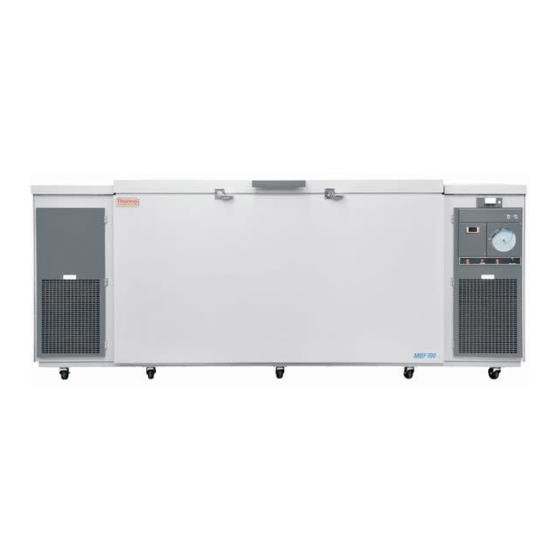
SECTION 1 – INTRODUCTION In this manual and on labels attached to this product, the words WARNING and CAUTION mean the following: WARNING: a potentially hazardous situation which, if not avoided, could result in serious injury or death. CAUTION: a potentially hazardous situation which, if not avoided, may result in minor or moderate injury or damage to the equipment. - Page 5 Figure 1 .General Freezer Outline (see Figure 3for control panel details) The interior useable space is also rectangular. The four corners are coved. With insulating sub lids in place it measures 71” long (180.3cm) x 35.37” high (89.9cm) x 22.63” deep (57.5cm). The interior volume is 31 Ft. (878.7 liters.) The cabinet is insulated with nominal 5”...
-
Page 6: Section 2 - Receiving And Unpacking
If you find any damage, keep the packing materials and immediately report the damage to the carrier. Do not return goods to Thermo Scientific without written authorization. When submitting a claim for shipping damage request that the carrier inspect the shipping container and equipment. -
Page 7: Section 3 -- Installation
SECTION 3 -- INSTALLATION Do not attempt to operate this freezer until the preceding Installation Check List steps have been complete INSTALLATION CHECK LIST Date Initial The freezer is in place. The freezer has been leveled. Check freezer data plate voltage. Check supply voltage is the same as data plate. -
Page 8: Loosening Compressor Mounts
LOOSENING COMPRESSOR MOUNTS Compressors are mounted using the assembly illustrated at the right. When units are shipped from the factory, the motor compressors are rigidly secured to the base by the mounting components. Before these units are placed into operation, the Y2” top mounting nut must be loosened to allow the compressor to float on the springs. -
Page 9: Chart Recorder
CHART RECORDER Power Supply The recorder normally uses AC power when the system is Set Up and Operation operating. If AC power fails, the LED indicator flashes to alert you to a power failure. The recorder continues sensing cabinet To prepare the recorder to function properly, complete the temperature and the chart continues turning for approximately following steps: 24 hours with back-up power provided by the nine-volt battery. -
Page 10: Liquid Co2 Backup System
LIQUID CO2 BACKUP SYSTEM When connected to a user supplied siphon tank of liquid CO2, the backup system will provide a source of backup refrigeration in case of power failure to the mechanical refrigeration equipment. The control assembly operates on 120VAC, 1 , 60Hz. A backup battery supply is continuously charging for operation of the backup system during power failure. -
Page 11: Water Cooled Unit Connections
LCO2 Control System Battery Condition The charge level light illuminates when the battery is below 80% of full charge. It is also possible that the charge level light will illuminate when the control system is dispensing LCO2. Placing LCO2 control system in storage Any rise in temperature will cause a rapid rise of pressure of liquid CO2 trapped in the supply line. - Page 12 Page 10...
-
Page 13: Section 4 - Control Operation
SECTION 3 – CONTROL OPERATION NOTE A flat blade screwdriver (1/8” wide x 3 1/2” blade) will be required to adjust setpoints at items 4, 5, & 6. Indicator LED’s for display modes. a. Cabinet temperature setpoint (amber) Cold alarm setpoint (amber) c. - Page 14 All controls are located at the right end of the cabinet. The labeled illustration on the next page shows the panel top section with status indicator lights, control adjusting screws and system push buttons. Directly below the control panel at the left is the Digital Display window. The Emergency Stop button is on the right. To set the adjusting screws, use a flat blade screwdriver with a 1/8”...
-
Page 15: Section 5 -Operation And Maintenance
SECTION 4 – OPERATION AND MAINTENANCE OPERATOR'S RESPONSIBILITIES These paragraphs define the Operator's responsibilities for reporting trouble symptoms on startup NOTE of the freezer and also observing its operation on an ongoing basis in order to prevent any mechanical or electrical failures that could result in loss of blood products. Frequency Of Description Of Tasks, Observations &... -
Page 16: Cleaning The Freezer Surfaces
MAINTENANCE PROCEDURES CLEANING THE FREEZER SURFACES The inside and outside of the freezer are coated with a heat fused epoxy powder finish. It may be cleaned with any non-abrasive cleaner such as hand dish washing detergent. To prevent odors on the inside of the freezer after cleaning, it is recommended that, after cleaning with detergent, the entire surface be wiped with a clean cloth soaked with a solution of one-half(1/2) gallon of water and one-quarter (1/4) cup of baking soda. - Page 17 Ulteriori informazioni sulla conformità di Thermo Fisher Scientific con queste Direttive, l’elenco delle ditte di riciclaggio nel Vostro paese e informazioni sui prodotti Thermo Scientific che possono essere utili alla rilevazione di sostanze soggette alla Direttiva RoHS sono disponibili sul sito www.thermo.com/ Conformité...
- Page 18 Important For your future reference and when contacting the factory, please have the following information readily available: Model Number: Serial Number: Date Purchased: The above information can be found on the dataplate attached to the equipment. If available, please provide the date purchased, the source of purchase (manufacturer or specific agent/rep organization), and purchase order number.
- Page 19 Thermo Fisher Scientific Inc. 275 Aiken Road Asheville, NC 28804 United States www.thermofisher.com 316004H01...
Need help?
Do you have a question about the Harris MBF-700 and is the answer not in the manual?
Questions and answers