Manual Defrost Procedure (Models 3556-4, 3556-6, 3557-2, 3557-4, 3750, 3750-1, 3752 and 3752-1) ....31 Manual Defrost Procedure (Model 3772 only) ......................32 Reversing the Front Door (Model 3551)........................33 Reversing the Front Door (Models 3556, 3557 and 3751) ..................34 Reversing the Front Door (Models 3772)........................35 Replacement Parts ................................37...
Safety Information Alert Signals Thank you for selecting Thermo Scientific products for your equipment needs. These instructions contain impor- tant operating and safety information. The user must carefully read and understand these instructions before Warning using the unit. Your unit has been designed to optimize Warnings alert you to a possibility of function, reliability, safety and ease of use.
Underwritersʼ Laboratory, Inc., OSHA and National Fire Protection Association for storage of hazardous materials. Thermo Scientific Explosion-Proof Refrigerators and Freezers are 100% explosion-proof. They also meet National Fire Protection Standards as found in Articles 500- 501 and provide total protection while storing reagents at or below ambient temperatures.
They are NOT designed for use in Class I, Groups C and D environ- ments. For these locations use a Thermo Scientific Explosion-Proof Refrigerator. However, FMS units are not suitable for use in Class I, Group C and D environ- ments.
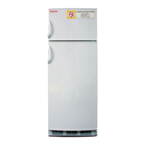
LAMMABLE ATERIALS TORAGE NITS MODEL 3551-10, 3551-11 23.5” Wide, Two-door refrigerator/freezer Features: • Overall 11 cu. ft. • Adjustable thermostat • ABS plastic interior Note • Manual defrost In order for freezer to reach -20°C, • White color vent on inside upper rear of refrigerator must be closed.
Cool Lab, General-Purpose Laboratory Refrigerators/Freezers Overview MODEL 3750, 3750-1 21.25” Wide, Refrigerator/freezer These are general-purpose units available in all refrigera- tor, all freezer and combination refrigerator/freezer mod- Features: els. • One-piece seamless interior MODEL 3751, 3751-1 • Two rustproof, slide-out shelves 23.33”...
Unpacking and Installation Shipping Carton This should be inspected upon delivery. When received, carefully examine for any shipping damage before unpacking. If damage is discovered, the delivering carrier should both specify and sign for the damage on your copy of the delivery receipt. Open the carton carefully making certain that all parts are accounted for before packaging materials are discarded.
NSTALLATION Electrical Caution Units must be connected to a grounded outlet matching DO NOT REMOVE, under any cir- the nameplate and/or the information furnished in this cumstance, the grounding prongs manual. from the 3-prong power cord sup- plied with all units. If you are not sure about the outlet, you should contact a qualified electrician for assistance.
NSTALLATION How to Seal Killark Box Conduit with Fiber and ® Sealing Compound to Help Protect Against Explosions (Explosion-Proof Units Only): The purpose of the procedure that follows is to build fiber rope dams on the left and right hubs of the horizontal conduit. The fiber rope damns will surround conduit wiring that is housed inside the horizontal conduit.
Page 22
NSTALLATION Figure 2: Horizontal Conduit, Cutaway Wiring Left Hub Right Hub • Insert fiber rope material down into horizontal conduit opening. Pressing down firmly, work the material into the left hub and—most importantly—being sure the material COMPLETELY SURROUNDS THE WIRING, from the top to the bottom, completely blocking this end of the horizontal conduit.
Page 23
NSTALLATION • Pour sealing compound down in between the two fiber rope dams filling the remaining space. Pour slowly, being careful not to trap air bubbles. Immediately wipe off any spilled sealing compound. • Screw conduit domed-cover back onto conduit opening. NOTE: INITIAL SETUP OF SEALING COMPOUND WILL OCCUR IN APPROXIMATELY 30 MINUTES HOW- EVER, THE SEALING COMPOUND REQUIRES A MINIMUM OF 8 HOURS ABOVE 32ºF TO DEVELOP SUFFICIENT STRENGTH TO WITHSTAND EXPLOSIONS.
Operation Environmental Operating Conditions POLLUTION DEGREE*: INSTALLATION CATEGORY*: ALTITUDE: 2000 Meters MSL (Mean Sea Level) HUMIDITY: 80% maximum, non-condensing ELECTRICAL SUPPLY: 120VAC or 240VAC VOLTAGE TOLERANCE: ±10% of normal rated line TEMPERATURE: 15ºC to 40ºC PRODUCT USAGE: This product is intended for use indoors only *Refer to IEC 664-1 Start-Up Procedure Rotate the control knob clockwise to lower the tempera-...
PERATION Control Panel Lights (Model 3753) Warning Lamp, Top, Red: This light works only • for the freezer compartment. It illuminates when the temperature decreases from the set point then turns off when the freezer has achieved set point again. This lamp will also light when the unit is turned on and is still at room temperature and will turn off when the unit begins to cool.
PERATION How to Save Energy • Be sure to follow location suggestions as men- tioned in the previous INSTALLATION section. • Wipe moisture from glassware or other materials before placing them in a unit. • Don't overcrowd the unit. Too many items can increase electrical energy demand in order to keep everything cool.
Optional Equipment Optional Buzzer Alarm ALARM STATUS LAMP POWER ALARM DELAY ADJUST ADJUST HIGH ALARM ALARM DISPLAY DISPLAY TEMPERATURE DISPLAY (4): Digital devices generally do not round off a reading. In the case of this temperature monitor, when the display reports, say a value of 10 degrees, that “10”...
Page 28
PTIONAL QUIPMENT ALARM CONDITIONS: • HIGH SETPOINT ALARM: If the probe tempera- ture exceeds the HIGH setpoint (or falls below the LOW setpoint on dual setpoint models), the audio alarm will sound the red ALARM status lamp (6) will flash. The unitʼs audio alarm can temporarily be silenced by depressing the DELAY button (7).
Troubleshooting In the event that your unit is not operating properly, check the following before calling for service assistance— this may save you the cost of unnecessary service calls. . y l , s i . t i n i l l l i o l l .
Note Make no attempt to service or repair • Set the temperature control to the OFF position. a Thermo Scientific product under warranty before consulting your • The unit designs permit easy and rapid cleaning Thermo Scientific dealer. After the and should not take more than a few minutes.
AINTENANCE Manual Defrost Procedure (Models 3556-4, 3556-6, 3557-2, 3557-4, 3750, Caution Do not use any sharp instrument, 3750-1 and 3752) blade or scraper to remove ice and frost on refrigerator surfaces Use the following procedure to defrost manually: because of the very real danger of •...
AINTENANCE Manual Defrost Procedure (Model 3772 Only) Caution Do not use any sharp instrument, blade or scraper to remove ice and Use the following procedure to defrost manually: frost on refrigerator surfaces Turn the temperature control knob to the 0 set- because of the very real danger of ting.
AINTENANCE Reversing the Front Door (Model 3551) Switch off at the socket outlet and pull out the mains plug. Remove all food from the appliance. Using a cross-headed screwdriver, remove the top hinge screws. Remove the top hinge while holding the door.
AINTENANCE Reversing the Front Door (Model 3556, 3557 and 3751) Remove bolts and plugs using a screwdriver. Unscrew the bolts connecting the upper hinges to the upper platform. Remove the upper platform by first pulling it forward and then lifting it upwards. Remove the door by unscrewing the bolts in the upper hinges.
AINTENANCE Reversing the Front Door (Model 3772) Turn thermostats to 0 and disconnect power cords Remove all items from inside the appliance Using the proper hex screwdriver, remove the top hinge screws Remove the top hinge while holding the door Lift the door carefully from the middle hinge Remove the middle hinge and lift the lower door off of pivot...
Page 36
AINTENANCE Remove plastic caps on the new middle hinge side. Remove screw and mount lower door and fasten middle hinge Remove the door handle by removing mounting screws and remount on opposite side 10. Mount the upper door on pivot and fasten the upper hinge on opposite side then tighten screws 11.
Replacement Parts To obtain replacement parts information and pricing, please call the Customer Service Department at 1-800- 553-0039 and have the unitʼs model, serial and code numbers available. This information is located on data plates on the rear of the unit.
Ordering Procedures Please refer to the Specification Plate for the complete model number, serial number, and series number when requesting service, replacement parts or in any corre- spondence concerning this unit. All parts listed herein may be ordered from the Thermo Scientific dealer from whom you purchased this unit or can be obtained promptly from the factory.
(ii) misuse (including use inconsistent with written operating instructions for the product), mishandling, contamination, overheating, modification or alteration of the product by any customer or third party or (iii) use of replacement parts that are obtained from a party who is not an authorized dealer of Thermo Scientific prod- ucts.
Need help?
Do you have a question about the 3551 and is the answer not in the manual?
Questions and answers