Table of Contents
Advertisement
Advertisement
Table of Contents

Subscribe to Our Youtube Channel
Related Manuals for Trio MC403-X


Summary of Contents for Trio MC403-X
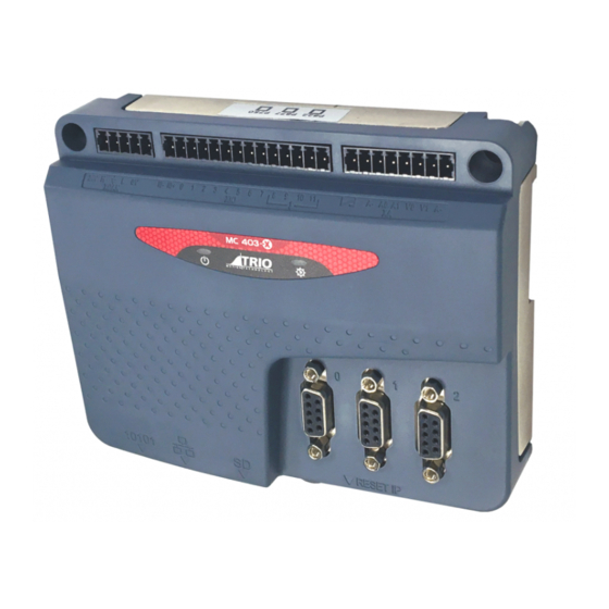
- Page 1 MC403-X 3 AXIS MOTION COORDINATOR USER MANUAL...
- Page 2 WDOG OFF Open the solid-state relay to signal that the Drives must be Disabled. Motion Perfect The PC Tool for commissioning and programming the Trio product suite. An electronic output from the Motion Coordinator that produces one pulse per step Pulse+Direction of the motor position, with a second output to signal the direction of motion.
-
Page 3: Revision History
MC403-X Revision History Date Version Revised Contents 20 Dec 2022 1.00 First Release Document Version: 1.00 © 2023 All rights reserved. - Page 4 MC403-X All goods supplied by Trio are subject to Trio’s standard terms and conditions of sale. This manual applies to systems based on the Motion Coordinator MC403. The material in this manual is subject to change without notice. Despite every effort, in a manual of this scope errors and omissions may occur.
- Page 5 MC403-X Safety Warning During the installation or use of a control system, users of Trio products must ensure there is no possibility of injury to any person, or damage to machinery. Control systems, especially during installation, can malfunction or behave unexpectedly.
-
Page 6: Table Of Contents
AXIS POSITIONING FUNCTIONS ..............7 CONNECTIONS TO THE MC403 ETHERNET PORT CONNECTION ........ 8 MC403-X SERIAL CONNECTIONS ..............8 SERIAL CONNECTOR ................. 9 MC403-X PULSE OUTPUTS / ENCODER INPUTS ..........9 REGISTRATION ..................10 5-WAY CONNECTOR ................10 I/O CONNECTOR 1 ................. 11 24V INPUT CHANNELS ................ -
Page 7: User Manual Mc403-X
Programs and data are stored directly to Flash memory, thus eliminating the need for battery backed storage. The Multi-tasking version of Motion- iX for the MC403-X allows up to 6 Motion-iX programs to be run simultaneously on the controller using pre-emptive multi-tasking. In addition, the operating system software includes the IEC 61131-3 standard run-time environment (licence key required). -
Page 8: Removable Storage
MC403-X The MC403-X has one built in RS232 port and one built in duplex RS485 channel for simple factory communication systems. Either the RS232 port or the RS485 port may be configured to run the Modbus or Hostlink protocol for PLC or HMI interfacing. -
Page 9: Connections To The Mc403 Ethernet Port Connection
To reset the IP _ ADDRESS, IP _ GATEWAY and IP _ NETMASK to their default values press the IP reset button and power cycle the controller while keeping the button pressed. MC403-X SERIAL CONNECTIONS The MC403-X features two serial ports. Both ports are accessed through a single 8 pin connector. Document Version: 1.00... -
Page 10: Serial Connector
Serial port #2 MC403-X PULSE OUTPUTS / ENCODER INPUTS The MC403-X is designed to support any combination of servo and pulse input motor drives on the standard controller hardware. The MC403-X has 3 versions, which are selected by applying Feature Enable Codes (FECs) 1) 2 axis as either encoder or pulse output. -
Page 11: Registration
*5V supply is limited to 150mA (shared with serial port) REGISTRATION Each MC403-X encoder port has 2 available registration events. These are assigned in a flexible way using REG_INPUTS to any of the 8 digital inputs or can be used with the Z mark input on the encoder port. -
Page 12: I/O Connector 1
MC403-X 24V d.c., Class 2 transformer or power source required for UL compliance. The MC403-X is grounded via the metal chassis. It MUST be installed on an unpainted metal plate or DIN rail which is connected to earth. An earth screw is also provided on the rear of the chassis for bonding the MC403-X to ground. -
Page 13: I/O Connector 2
ANALOGUE OUTPUTS The MC403-X has 2 12-bit analogue outputs scaled at +/-10V. Each output is assigned to one servo axis, or in the case where the axis is not used, or is set as a Document Version: 1.00... -
Page 14: Led Display
A 24V d.c. supply must be applied to I/O connector 1 to provide power for the analogue output circuit. LED DISPLAY On power-up, the LEDs flash to show the MC403-X version and the SD card status. P865 2 axis pulse output version: 3 flashes of the RED LED. -
Page 15: Mc403-X Feature Summary
Product Codes P865 : MC403-X 2 axis stepper output / 2 encoder input P866 : MC403-X 1 axis servo + 2 encoder / 2 axis stepper P867 : MC403-X 2 axis servo + 1 encoder / 3 axis stepper Document Version: 1.00... -
Page 16: Mc403-X Axis Configuration Summary
MC403-X MC403-X AXIS CONFIGURATION SUMMARY CONFIGURATION P867 P866 P865 AXIS 0 Extended+AS Extended+AS* Extended AXIS 1 Extended+AS Extended* Extended AXIS 2 Extended Extended AXES # of axes (max) # of virtual axes (max) DRIVE INTERFACES Stepper (Step & Direction) Servo (±10V & Encoder) -
Page 17: Extended Functionality
Pulse and direction output with enable output Quadrature encoder output with enable output Pulse and direction output with Z input Quadrature encoder output with Z input Trio Motion Technology HARDWARE OVERVIEW Motion Coordinator MC403 2-54 Incremental encoder with Z input...
Need help?
Do you have a question about the MC403-X and is the answer not in the manual?
Questions and answers