Advertisement
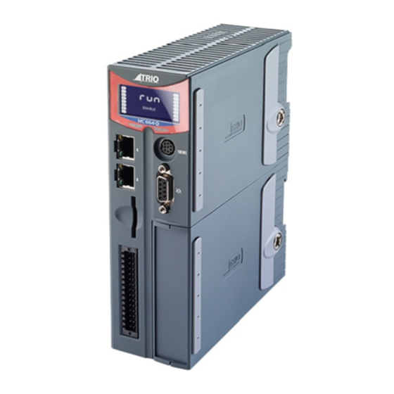
Backlit Status Display
and LEDs
RS232 / RS485 Modbus-rtu,
hostlink or user program-
mable
Ethernet Programming
Modbus-TCP , Ethernet-IP , Trio
Activex, UNIPLAY HMI, UDP
Port
Extended flexible axis
Extended flexible axis
SD Card
I/O, CAN, Power,
Analogue, WDOG
MOTION COORDINATOR
TION COORDINATOR
MC664 / MC664-X
Quick Connection Guide
This guide must be used in conjunction with the Technical Reference Manual
Panel Mount or DIN
Rail Mount
Easy Release Expan-
sion Cover
Common Earthing
For Improved Noise
Rejection
First Expansion
Module
Advertisement
Table of Contents

Related Manuals for Trio MC664


Summary of Contents for Trio MC664
- Page 1 RS232 / RS485 Modbus-rtu, sion Cover hostlink or user program- mable Common Earthing For Improved Noise Rejection Ethernet Programming Modbus-TCP , Ethernet-IP , Trio Activex, UNIPLAY HMI, UDP Port First Expansion Module Extended flexible axis Extended flexible axis SD Card...
-
Page 2: Non-Volatile Memory
MC664(X) FEATURE SUMMARY MC664 MC664-X Processor ARM A9 Single Core ARM A9 Quad Core Servo update rate 125 to 4000 usecs 50 to 4000 usecs Maximum axes Absolute encoder support EtherCAT axes included EtherCAT registration Inputs 0 to 7 Inputs 0 to 7... - Page 3 0V AIN 0V CAN/AIN AIN0 CAN LOW used to provide the 24V dc power AIN1 CAN EARTH to the MC664. A 24V dc, Class 2 WDOG+ CAN HIGH transformer or power source must WDOG- 24V CAN/AIN SUPPLY be provided. I/O8...
-
Page 4: Serial Connections
SERIAL 8 Way MiniDIN Function Note CONNECTIONS RS485 Data In A Rx+ Serial Port #2 RS485 Data In B Rx- RS232 Transmit Serial Port #1 0V Serial RS232 Receive Serial Port #1 Internal 5V RS485 Data Out Z Tx- Serial Port #2 RS485 Data Out Y Tx+ SYNC ENCODER 9 Way D-Type... - Page 5 ADDING EXPANSION Recovery MODULES Normal Unscrew the lower retaining fi xing (A) using the supplied tool or a coin. Remove the covers from the module (B). Swing the expansion module (C) out from the rear and unclip from the front end. Replacing the module is the reverse of the procedure.
- Page 6 Display at start-up Display with WDOG on ENABLE The model number, IP address and subnet mask of the MC664 are shown on the LCD display for a few seconds after power-up. The factory default IP address is 192.168.0.250. This can be changed using the ETHERNET or the IP _ ADDRESS command via Motion Perfect.
- Page 7 A maximum of 7 half height modules or 3 full height modules may be ASSEMBLY fi tted to the MC664. A system may be made using any combination of half and full height modules providing that the full height modules are the last to be attached.
- Page 8 EXPANSION MODULE P871 - MC664 PANASONIC INTERFACE REGISTRATION R0 - R7: registration inputs (24V). CONNECTOR R0V: registration common 0V return. Registration inputs can be allocated to any axis by software. Note: This pin out applies to module serial numbers P871-00011 and higher.
-
Page 9: Led Functions
LED FUNCTIONS LED Colour LED Function Green ON=Module Initialised Okay ON=Module Error Yellow Status 1 Yellow Status 2... - Page 10 EXPANSION MODULE P872 - MC664 SERCOS INTERFACE REGISTRATION R0 - R7: registration inputs (24V). CONNECTOR 0V: registration common 0V return. Registration inputs can be allocated to any axis by software. CONNECTOR (TX) sercos fi bre-optic transmit. 9mm FSMA CONNECTOR (RX) sercos fi...
- Page 11 LED FUNCTIONS LED LED Colour LED Function Green ON=Module Initialised Okay ON=Ring Open / Distorted Yellow SERCOS Phase Yellow SERCOS Phase SERCOS PHASE LED 1 LED 2 FLASH FLASH...
- Page 12 EXPANSION MODULE P873 - MC664 SLM INTERFACE REGISTRATION R0 - R5: registration inputs (24V). CONNECTOR 0VR: common 0V return. 0V PWR: Power input for SLM system. 24V: 0V PWR SLM CONNECTOR 15 Way D-Type Upper D-Type Lower D-Type Com Axis 0 Com Axis 3 /Com Axis 0.
- Page 13 LED FUNCTIONS LED Colour LED Function Green ON=Module Initialised Okay ON=Module Error Yellow Status 1 Yellow Status 2...
- Page 14 EXPANSION MODULE P874 / P879 - MC664 FLEXIBLE AXIS INTERFACE REGISTRATION V0 - V7: Voltage outputs CONNECTOR R4/PS4 - R7/PS7: Bidirectional registration R0 - R3: Registration In Inputs / 24V: PSwitch outputs 0V PWR: Power Input 24V: Power Input R4/PS4...
-
Page 15: Encoder Connector
ENCODER 15 Way D-Type Incremental Absolute Pulse & CONNECTOR Encoder Encoder Direction Enc. A n Clock n Step.+ n Enc. /A n /Clock n Step.- n Enc. B n -------- Direction+ n Enc. /B n -------- Direction- n 0V Enc. 0V Enc. - Page 16 (C) on the lower front edge of the Anybus® module locate under the P875 PCB at the front. When the module is fl ush with the face of the Trio Expansion Interface, tighten the two “Torx” head screws (D) to locate the two lugs (E) and secure the Anybus®...
- Page 17 EXPANSION MODULE P876 - MC664 ETHERCAT INTERFACE REGISTRATION R0 - R7: registration inputs (24V). CONNECTOR 0V: registration common 0V return. Registration inputs can be allocated to any axis by software. RJ45 100 base-T Ethernet master. Connect to IN of CONNECTOR...
- Page 18 LED FUNCTIONS LED Colour LED Function Green ON=Module Initialised Okay ON=Module Error SLOW FLASH=Not in Operational State QUICK FLASH=EtherCAT Error Yellow Status 1 Yellow EtherCAT Activity...
- Page 19 UK | USA | CHINA | INDIA WWW.TRIOMOTION.COM T H E M O T I O N S P E C I A L I S T All trade marks acknowledged. quick start v1-January 2016...
Need help?
Do you have a question about the MC664 and is the answer not in the manual?
Questions and answers