Table of Contents
Advertisement
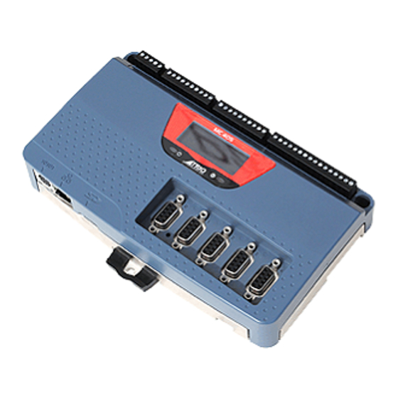
CAN PORT FOR TRIOCAN
I/O, DEVICENET SLAVE,
CANOPEN OR USER
PROGRAMMABLE
LED DISPLAY AND
AY AND
STATUS LED'S
LED'S
RS232 / RS485
MODBUS-RTU,
HOSTLINK OR USER
PROGRAMMABLE
ETHERNET
PROGRAMMING, MODBUS-
TCP, ETHERNET IP
MOTION
MOTION COORDINATOR
Quick Connection Guide
(Please refer to the Motion Coordinator Technical Reference Manual for Full Details)
8 INPUTS INCLUDING
8 REGISTRATION INPUTS
8 BI-DIRECTIONAL I/O
MICRO SD CARD
MC405
WDOG RELAY
PANEL MOUNT AND DIN
5 ENCODER CONNECTIONS
(6MHZ) OR DRIVE AS
STEPPER OUTPUT (2MHZ)
RAIL MOUNT
Advertisement
Table of Contents

Related Manuals for Trio MC405


Summary of Contents for Trio MC405
- Page 1 HOSTLINK OR USER PROGRAMMABLE 5 ENCODER CONNECTIONS (6MHZ) OR DRIVE AS STEPPER OUTPUT (2MHZ) ETHERNET MICRO SD CARD PROGRAMMING, MODBUS- TCP, ETHERNET IP MOTION COORDINATOR MOTION MC405 Quick Connection Guide (Please refer to the Motion Coordinator Technical Reference Manual for Full Details)
- Page 2 Windows based PC that is fi tted with an Ethernet connection. The IP address is displayed on the MC405 display for a few seconds after power-up or when an Ethernet cable is plugged in. Ethernet cable must be CAT 5 or better.
- Page 3 Serial Connector SERIAL CONNECTIONS Function Note RS485 Data In A Rx+ Serial Port #2 RS485 Data In B Rx- RS232 Transmit Serial Port #1 0V Serial RS232 Receive Serial Port #1 RS485 Data Out Z Tx- Serial Port #2 RS485 Data Out Y Tx+ I/O CONNECTOR 1 I/O 0V I/O 0V...
- Page 4 I/O CONNECTOR 2 I/O 0V I/O 24V Input / Output Channel 8 Input / Output Channel 9 Input / Output Channel 10 Input / Output Channel 11 Input / Output Channel 12 Input / Output Channel 13 Input / Output Channel 14 Input / Output Channel 15 24V Power / I/O 8-15 24V Pin...
- Page 5 Amplifi er 24V 0V Enable 1 Amplifi er Enable Enable 2 VIN + VIN- Trio Controller Servo Amplifi er ANALOGUE INPUT S ANALOGUE OUTPUTS AIN0: 0 TO 10V AOUT 0 TO AOUT 3 AIN1: 0 TO 10V Output: +/-10V at 5mA Output impedance: 100 Ohms.
- Page 6 STEPPER STEP 5 4 3 2 1 OUTPUTS / ENCODER INPUTS 9 8 7 6 DIRECTION 5 4 3 2 1 9 8 7 6 5 4 3 2 1 ENABLE 9 8 7 6 5 4 3 2 1 9 8 7 6 Current Limit 5 4 3 2 1...
- Page 7 Power 24V+ CANbus (H) Ensure that: SHEILD 1. The shield screw is grounded CANbus (L) as close to the MC405 as possible. 24V Return (-) 2. 0V, V- and E- connections are SERVO DRIVE NOT used for terminating I/O CONNECTOR 3 screens.
- Page 8 Display with WDOG on ENABLE The IP address and subnet mask of the MC405 is shown on the LCD display for a few seconds after power-up. The factory default IP address is 192.168.0.250. This can be changed using the ETHERNET or IP_ADDRESS commands via Motion Perfect.
Need help?
Do you have a question about the MC405 and is the answer not in the manual?
Questions and answers