Table of Contents
Advertisement
Quick Links
Advertisement
Table of Contents

Related Manuals for Owon CM240


Summary of Contents for Owon CM240
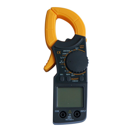
- Page 1 Digital Clamp Meter User Manual CM240 WWW.OWON.COM.CN...
- Page 2 LILLIPUT Company. Fujian LILLIPUT Optoelectronics Technology Co., Ltd. No. 19, Heming Road Lantian Industrial Zone, Zhangzhou 363005 P.R. China Tel: +86-596-2130430 Fax: +86-596-2109272 Web: E-mail: info@owon.com.cn www.owon.com.cn...
-
Page 3: Table Of Contents
Table of Contents Instruction ............. 1 Check the Accessories ........1 Safety Information ......... 1 Electrical Symbols .......... 3 Front Panel Description ......... 3 LCD Display Symbols ........4 Button Function and Auto Power Off .... 4 Making Measurements ........5 Measuring DC Voltage ........... -
Page 4: Instruction
Instruction Instruction CM240 digital clamp meter is a - digit LCD multi-meter with steady operations, fashionable structure and highly reliable measuring instrument. The meter uses large scale of integrated circuit with double integrated A/D converter as its core and has full range overload protection. The meter can perform measurements of AC and DC voltage, AC current, resistance, diode and continuity test. - Page 5 Safety Information 1. Read the operating instructions before using the instrument and pay particular attention to all WARNINGS and CAUTIONS in this instruction manual. 2. Be sure that the cover and the test leads of the meter are in good conditions. 3.
-
Page 6: Electrical Symbols
Electrical Symbols Electrical Symbols Double Warning Earth insulated Ground (Protection class II) Direct Alternating Continuity signal signal test buzzer test Diode test Low Battery AC or DC Conforms to European Union directives Application around and removal from HAZARDOUS LIVE conductors is permitted. Capacitor Front Panel Description 1. -
Page 7: Lcd Display Symbols
LCD Display Symbols LCD Display Symbols 1. Alternating signal test 2. Direct signal test 3. Low Battery 4. Auto range mode 5. Diode test 6. Continuity buzzer 7. The maximum value is being measured 8. This indicates that the display data is being held 9. -
Page 8: Making Measurements
Making Measurements Note: After automatic turn-off, then press H to re-start, the function of automatic turn-off will be cancel. 5. Buzzer Set the selector to any measuring function (except 2/20A ACV function), press any button, the buzzer will sound; otherwise, the button is idleness. -
Page 9: Measuring Ac Voltage
Making Measurements 1) Plug the black test lead into the COM jack and the red test lead into the INPUT Jack. 2) Set the rotary switch to V position to make the meter get into DC V range. 3) Connect the test leads to the voltage source or load terminals for measurement. -
Page 10: Measuring Resistance
Making Measurements and remove testing leads from the input terminals. Measuring Resistance WARNING To avoid possible damage to your multimeter or to the equipment under test, disconnect the circuit power and discharge all high-voltage capacitors before measuring resistance. 1) Plug the black test lead into the COM jack and the red test lead into the INPUT Jack. -
Page 11: Testing Continuity
Making Measurements 1) Plug the black test lead into the COM jack and the red test lead into the INPUT Jack. 2) Set the rotary switch to Ω/ range position. 3) Press the "SEL" button to switch to test. 4) Connect the red test leads to the anode and the black test lead to the cathode of the diode for testing. -
Page 12: Measuring Ac Current
General Specifications The buzzer may or may not sounds if the resistance of a circuit under test is between 30Ω to 100Ω. The buzzer does not sound if the resistance of a circuit under test is higher than 100Ω. Measuring AC Current WARNING Beware of Electrocution. -
Page 13: Electrical Specifications
Electrical Specifications 10. Auto power off time: 15 min 11. Operation temperature: 0 to 30℃ (≦75%RH), 30℃ to 40℃ (≦70%RH), 40℃ to 50℃ (≦40%RH) 12. Storage temperature: -20℃ to 60℃, ≦75%RH 13. Operation power: Two 1.5V, AAA batteries 14. Dimension: 65mm(W) x 177mm(L) x 28mm(D) 15. - Page 14 Electrical Specifications 3. Resistance: Auto Range Range Resolution Accuracy Overload protection ± (1.2%+5d) 200.0 Ω 100 mΩ 2.000 kΩ 1 Ω ± (1%+3d) 20.00 kΩ 10 Ω 600 Vp 200.0 kΩ 100 Ω 2.000 MΩ 1 kΩ ± (1.2%+5d) 20.00 MΩ 10 kΩ...
-
Page 15: Replacing The Batteries
Replacing the Batteries 6. AC Current: Auto Range Range Resolution Accuracy Frequency Overload Response protection ±(4%+20d)≦0.4A 2.000 A 1 mA ±(3%+15d) ±(3%+15d)≦0.4A 50 Hz - 20.00 A 10 mA 400 A rms 60 Hz ±(2%+10d) 200.0 A 0.1 A ±(2%+5d) 400 A Response: Average responding, calibrated in rms of sine wave Replacing the Batteries...
Need help?
Do you have a question about the CM240 and is the answer not in the manual?
Questions and answers