Advertisement
Quick Links
Advertisement

Related Manuals for Owon PC341-W-TY


Summary of Contents for Owon PC341-W-TY
- Page 1 Smart Life App PC341-W-TY Multi-Circuit Power Meter Quick Start Guide...
-
Page 2: Safety Handling
Safety Handling WARNING: Failure to follow these safety notices could result in fire, electric shock, other injuries, or damage to the Power Meter and other property. Read all the safety notices below before using the Power Meter. • Avoid high humidity or extreme temperatures. •... -
Page 3: Technical Specifications
Technical Specifications Wireless Connectivity Wi-Fi • 802.11 b/g/n @ 2.4GHz • Operating frequency: 2.4GHz RF Characteristics • External magnetic antenna Physical Specifications Operating Voltage • 90~380 Vac 50/60 Hz • Single-Phase up to 380VAC line- neutral Supported Systems • Split-Phase 120/240VAC •... - Page 4 Welcome PC341-W-TY Power Meter helps you monitor the amount of electricity Consumed and Production in your facility by connecting the clamp on to the power cable. This guide will provide you with an overview of the product and help you get through the initial setup to installation.
-
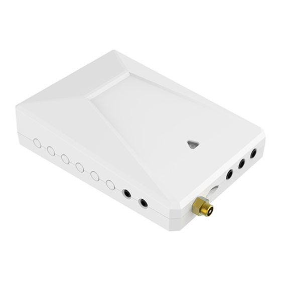
Page 5: Get To Know Your Device
Get to know your device LED indicator Main Unit Main CTs 50A Sub CTs (3.5mm audio plug) (2.5mm audio plug) External Antenna Power cable Mounting bracket... - Page 6 All of the ports are labeled on the back of the main unit. 1. The 3.5mm L1/A, L2/B, and L3/C audio ports on the top of the main unit are the inputs for the Main CTs. Only for Cellular Version For 3.5mm audio Mains CTs: L1/A...
-
Page 7: Reset Button
Reset Button • Reset. Press and hold the reset button for 5 seconds until the LED indicator flashes red 3 times quickly to restore the Power Meter to default factory settings (energy data will not be cleared). If you want to clear the energy data, please delete the device and wipe data on the app and add it again. - Page 8 01 Turn off power You need to turn off the main breaker in your electric panel to shut off all of the power in your home (However, the service mains are always live!). Then remove screws securing the cover to the panel to access the circuit breakers.
- Page 9 03 Install the antenna Locate the External Antenna outside the electrical panel to ensure that that the Power Meter signal is not blocked by metal (The base of the antenna has a magnetic and can be adsorbed on iron materials). After that , screw the External Antenna to the Antenna connector.
- Page 10 2. Clamp one Main CT on each main service lines. Make sure the arrow on the CT must point towards the breakers! Your system may have 1, 2, or 3 main service lines, and a corresponding number of Main CTs are required.
- Page 11 4. Insert each 3.5mm audio plug of Main CT into the corresponding audio jack on the top of the Power Meter: • The CT measuring the L1/A line should plug into the audio jack labeled L1/A. • The CT measuring the L2/B line should plug into the audio jack labeled L2/B.
- Page 12 2. Secure N wire from the power cable to the neutral bus bar and L1 wire to the L1/A breaker pole. L1/A L2/B L3/C If your system is 3-Phase, secure the L2, L3 wire corresponding to L2/B, L3/C breaker pole. L1/A L2/B L3/C...
- Page 13 If your system is Single Phase, the L2 and L3 wire need to connect to the neutral bus bar. L1/A Single Phase 06 Clamp Sub CTs around the circuit If you don't have Sub CTs(2.5mm audio plug), skip this step. 1.
- Page 14 2. Clamp each Sub CTs around the circuit you wish to monitor. Make sure the arrow on the CT must point towards the load or Inverter! Load Breakers Inverter Loads Inverter L1/A Note: If the circuit you are monitoring can generate energy such as Inverter, etc., after all the wiring is completed, please manually set the phase of the circuit in the app settings, otherwise the power measurement will be incorrect.
- Page 15 07 Wiring reference Warning: The service mains are always live! Loads Inverter L1/A L2/B L3/C 3-Phase Most in European 3-phase homes and US Commercial systems...
- Page 16 Warning: The service mains are always live! L1/A L2/B Split-Phase Most in US homes with Load Monitoring...
- Page 17 Warning: The service mains are always live! Inverter L1/A L2/B Split-Phase Most in US homes with Solar Monitoring...
- Page 18 Single Phase Most in European 1-phase homes...
- Page 19 Configure Network Download App Please download the application: Smart Life from App Store or App Market. Also you can scan below QR code to download and install. Method 1: 1. Open Smart Life app and click the 'Scan' button in the upper right corner of the App Home page.
- Page 20 2. Scan the following QR code to configure the network . Method 2: 1. Power on the power clamp. 2. Make sure the LED indicator is flashing green. If not, please reset it. 3. Open Smart Life app and turn on Bluetooth on your phone.
- Page 21 4. Open the app and the scanned devices will pop up automatically. 5. If no prompt box pops up automatically, please click the '+' on the top right of the home page to add device. It will search nearby devices. 6.
- Page 22 Mounting The mounting bracket supports rail installation, you can click the three hooks on mounting bracket to the Din-Rail. Locate the hooks of the mounting bracket and line up the hooks with the mounting holes on the Power Meter. Fit the hooks into the mounting holes as the picture below.
Need help?
Do you have a question about the PC341-W-TY and is the answer not in the manual?
Questions and answers