Table of Contents
Advertisement
Quick Links
Advertisement
Table of Contents

Subscribe to Our Youtube Channel
Related Manuals for Wood-mizer LT15S3 E11S


Summary of Contents for Wood-mizer LT15S3 E11S
- Page 3 ® Wood-Mizer Sawmill Safety, Setup, Operation & Maintenance Manual LT15S3 E11S rev. E1.01 LT15M2 E11S rev. E1.01 Safety is our #1 concern! Read and understand all safety information and instructions before operating, setting up or maintaining this machine. May 2005...
- Page 4 +48-63-2626000 or +48-3912-1319. From the continental U.S., call our toll-free Parts hotline at 1-800-448-7881. Please have the vehicle identification number and your cus- tomer number ready when you call. Wood-Mizer will accept these methods of payment: Visa, Mastercard, or Select Purchase...
- Page 5 Sawmill and Customer Identification Each Wood-Mizer LT15 sawmill is identified with a revision and VIN numbers. The VIN number contains the month, year and place of manufacture, the base model and the engine/motor configuration. The revision number helps identify the exact design of the equipment.
-
Page 6: Table Of Contents
SECTION 1 SAFETY & GENERAL INFORMATION Blade Handling......................1-2 Sawmill Setup......................1-2 Sawmill Operation..................... 1-3 Sawmill Maintenance ....................1-5 Belt Sizes ......................... 1-10 Blade Sizes ......................1-10 Cutting Capacity...................... 1-11 Engine/Motor Specifications ................... 1-11 Overall Dimensions ....................1-12 1.11 Components......................1-14 SECTION 2 SAWMILL ASSEMBLY Mounting Parts of LT15 Sawmills with Electric Motors .......... - Page 7 SECTION 6 ALIGNMENT Pre-Alignment Procedures..................8-1 Preparing The Sawmill For Alignment ..............8-2 Blade Installation and Alignment................8-3 Blade Wheel Alignment .................... 8-5 Blade Guide Arm Alignment................... 8-10 Aligning The Blade Guides ..................8-12 Blade Deflection...................... 8-13 Blade Guide Vertical Tilt Adjustment..............8-14 Blade Guide Spacing ....................
- Page 8 15doc101107...
-
Page 9: Safety & General Information
It is always the owner's responsibility to comply with all applicable federal, state and local laws, rules and regulations regarding the ownership and operation of your Wood-Mizer sawmill. All Wood-Mizer mill owners are encouraged to become thoroughly familiar with these applicable laws and comply with them fully while using the mill. -
Page 10: Blade Handling
Safety & General Information Blade Handling Blade Handling DANGER! Always disengage the blade and shut off the sawmill engine before changing the blade. Failure to do so will result in serious injury. WARNING! Always wear gloves and eye protection when handling bandsaw blades. -
Page 11: Sawmill Operation
Safety & General Information Sawmill Operation Sawmill Operation DANGER! Make sure all guards and covers are in place and secured before operating or towing the sawmill. Failure to do so may result in serious injury. DANGER! Be sure the blade housing and pulley covers are in place and secured. - Page 12 Safety & General Information Sawmill Operation to do so may result in machine damage. CAUTION! Do not try to force the saw head beyond its upper and lower travel limits. Damage to the up/down sys- tem may result. CAUTION! Be sure to stop the blade when returning the carriage.
-
Page 13: Sawmill Maintenance
Safety & General Information Sawmill Maintenance Sawmill Maintenance CAUTION! The up/down screw bellows should completely cover the screw. If either of the bellows is damaged, replace it immediately. Before installing the new bellows, clean the up/down screw and nut thoroughly with extraction naphtha and then grease them. - Page 14 Safety & General Information Sawmill Maintenance See Table 1-1. Pictogram decals used to warn and inform the user about danger in the LT15. TABLE 1-1 Decal View W-M No. Description 096317 CAUTION! Read thoroughly the manual before operating the machine. Observe all safety instructions and rules when operating the sawmill.
- Page 15 Safety & General Information Sawmill Maintenance TABLE 1-1 099221 CAUTION! Keep all persons a safe distance away from work area when operating the machine. 099221 096316 CAUTION! Do not open or close the electric box when the switch is not in the “0”...
- Page 16 Safety & General Information Sawmill Maintenance TABLE 1-1 S12004G CAUTION! Always wear safety goggles when operating the sawmill! S12005G CAUTION! Always wear protective ear muffs when operating the sawmill! P11789 Aligning the blade on the wheels 092597 Setting the blade tension indicator 092597 P85070 CE safety certification...
- Page 17 Safety & General Information Sawmill Maintenance TABLE 1-1 099401 Russian safety certification 099401 S20097 Motor rotation direction S20097 Safety & General Information 15doc101107...
-
Page 18: Blade Sizes
Browning belts only. Blade Sizes See Table 1-3. Wood-Mizer TRU•SHARP™ offers three types of blades to provide effi- cient sawing for all models of sawmills. The engine/motor size of your sawmill and the type of wood you saw should determine which blade you choose for optimum perfor- mance. -
Page 19: Cutting Capacity
Up/Down Motor Besel SKh71X-4C2/HPS08 3x 230/400VAC, 50Hz 0.55kW TABLE 1-6 See Table 1-7. The noise levels of the Wood-Mizer sawmills are listed below. Idle Engaged Sawmill Equipped With G13 Engine 91.7 dB (A) 92.0 dB (A) Sawmill Equipped With D10 Engine 93.2 dB (A) -
Page 20: Overall Dimensions
Safety & General Information Overall Dimensions Overall Dimensions See Figure 1-1. The overall dimensions of the LT15 sawmills are shown below. 2652 2175 2482 2295 1989 150104 2025 LT15M2 2700 2700 6150 LT15S3 1950 1950 1950 6600 FIG. 1-1 1-12 15doc101107 Safety &... - Page 21 Safety & General Information Overall Dimensions 1.10 Dust Extractor Specifications See Table 1-8. Specifications of the dust extractors. Airflow 1200 m Inlet diameter 150 mm Motor power 1,5 kW Number of sacks 1 szt. Capacity of sacks 0.25 mp Weight 110 kg Recommended conveying air 20 m/s...
-
Page 22: Components
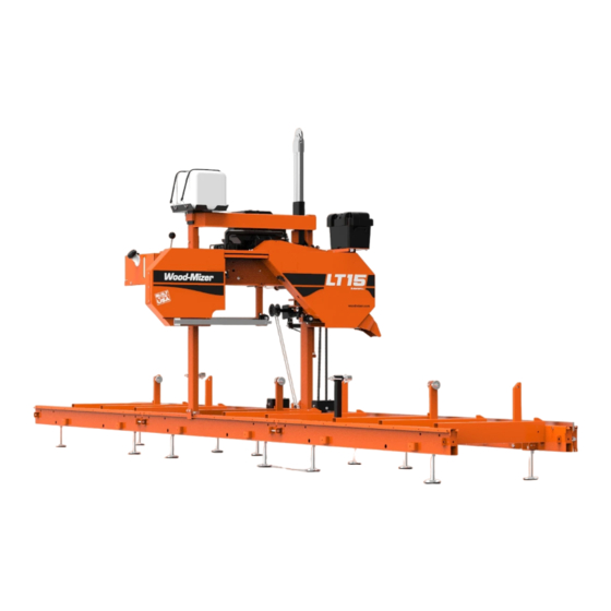
Safety & General Information Components 1.11 Components See Figure 1-2. The major components of the Wood-Mizer LT15 are shown below. Water Tank Sawmill Mast Up/Down Drive Assembly Saw Head Blade Tension Handle Blade Drive Motor Blade Guide Arm Handle Electric Box... -
Page 23: Sawmill Assembly
SAWMILL ASSEMBLY Mounting Parts of LT15 Sawmills with Electric Motors SECTION 2 SAWMILL ASSEMBLY Mounting Parts of LT15 Sawmills with Electric Motors 2.1.1 Parts specifications Tabel 1: Fig. Wood-Mizer Part Description Qty. Qty. LT15S3 LT15M2 094132 LT15 Sawmill Saw Head... - Page 24 SAWMILL ASSEMBLY Parts specifications Tabel 1: 095745-1 Leg Mounting Block 097553 Log Clamp 092570-1 Feed Rope Mount Bracket 085982-1 Log Side Support, Complete 094427-1 (LT15S3) Track Rail 094696-1 (LT15M2) R02080 Rope 086745 Middle Track Cover with Felt Wiper 086323 Left Track Wiper 086322 Right Track Wiper 093859...
- Page 25 SAWMILL ASSEMBLY Parts specifications Tabel 1: 092378-1 Bracket, Blade Guide Roller Guard 092379-1 Blade Guide Roller Guard 086132-1 Power Cord Bracket 095490-1 Auxiliary Bed Rail 092460-1 Sawdust Chute 085981-1 Thick Spacer Washer 086723-1 LT15 Foot Mount Plate Vertical Mast Lock Assembly 086743-1 Zinc-plated Pin F81045-1...
- Page 26 Power Feed Crank Handle 094142 Bushing 086338 Crank Handle Grip F81033-1 Hex Nylon Lock Nut 2.1.2 Specifications of Fasteners Tabel 2: Wood-Mizer No. Description Qty. Qty. LT15S3 LT15M2 Sample designations of fasteners: M8 Nut M8x20 Bolt 8.4 Washer F81056-1 13 Flat Washer...
- Page 27 SAWMILL ASSEMBLY Specifications of Fasteners Tabel 2: F81030-2 M5 Nut F81000-7 M5x25 Bolt F81053-11 6.5 Special Flat Washer F81001-15 M6x16-8.8 Bolt F81001-7 M6x12 Bolt F81054-1 8.4 Flat Washer F81032-2 M8 Nut F81002-5 M8x25 Bolt F81002-4 M8x20 Bolt F81055-2 10.2 Split Lock Washer 014972 33/64 x1”...
- Page 28 SAWMILL ASSEMBLY Tools Necessary for Assembling the Sawmill 2.1.3 Tools Necessary for Assembling the Sawmill Tabel 3: Required Tools Flat Wrench #8 1pcs Flat Wrench #10 2pcs Flat Wrench #13 2pcs Flat Wrench #17 2pcs Flat Wrench #19 2pcs Ratchet Wrench #30 1pcs Hammer 1pcs...
-
Page 29: Unpacking The Sawmill
SAWMILL ASSEMBLY Unpacking the Sawmill Unpacking the Sawmill FIG. 2-1 1. Cut the bands holding the components together. 2. Remove the parts arranged inside the bed section. 3. Using a forklift truck or a winch with lifting capacity of minimum 500 kg, carefully lift the saw head and set it aside. - Page 30 SAWMILL ASSEMBLY Unpacking the Sawmill See Figure 2-2. 500kg FIG. 2-2 15doc101107 SAWMILL ASSEMBLY...
-
Page 31: Bed Frame Assembly
SAWMILL ASSEMBLY Bed Frame Assembly Bed Frame Assembly IMPORTANT! With all screw joints without split lock washer or lock nylon nut, use the "LOCTITE 243" (blue, of average durability, for screw joints). 1. Mount preliminarily the track rail as shown in Figure 2-3. Do not tighten the nuts. See Figure 2-3. - Page 32 SAWMILL ASSEMBLY Bed Frame Assembly 2. Mount four leg brackets to each bed section. Use two hex head bolts and lock nuts to secure each leg bracket to the bed section. Be sure the nut on the bracket faces up. Thread a leg into each bracket.
- Page 33 SAWMILL ASSEMBLY Bed Frame Assembly 3. Lay the frame sections end-to-end so the track portion of each section is on the same side. Slide the sections together and secure with four hex head bolts and nylon lock nuts. See Figure 2-5. 10.2 Split Lock Washer M10x25 Bolt Frame Mounting...
- Page 34 SAWMILL ASSEMBLY Bed Frame Assembly 5. Mount a bed extension to the front and the rear ends of the bed frame. See Figure 2-6. M10x75 Bolt 086659-1 10.2 Split Lock Washer 10.5 Washer M12 Hex Nylon Lock M10x25 094250-1 13 Flat Bolt Washer M12x120 Bolt...
- Page 35 SAWMILL ASSEMBLY Bed Frame Assembly 7. Install the log side supports as shown in Figure 2-7. Tighten the nuts so that the side supports can be moved with little resistance. Adjust the side supports. See Section 6.11 See Figure 2-7. M10x20 Bolt M12 Nut 085981-1...
-
Page 36: Frame Leg Adjustment
SAWMILL ASSEMBLY Frame Leg Adjustment Frame Leg Adjustment 1. Place a foot plate under each bed leg. 2. Using an appropriate wrench, adjust each leg so that the nut is approximately 25mm below the top of the bed tube See Figure 2-8. 25mm Foot Plate FIG. -
Page 37: Saw Head Assembly
SAWMILL ASSEMBLY Saw Head Assembly Saw Head Assembly 1. Position the saw head at the end of the bed frame assembly. Carefully slide the saw head rollers onto the bed frame track. Keep the saw head square to the bed to avoid putting the track rollers in a bind. - Page 38 SAWMILL ASSEMBLY Saw Head Assembly washers. NOTE: Before installing the middle track cover and the remaining felt wipers, soak the felt strips with lubricating fluid (e.g. WD40). 6. Assemble mast safety pins. See Figure 2-10. Spring 087301 086743-1 Cotter Pin Washer F81043-2 F81058-1...
- Page 39 SAWMILL ASSEMBLY Saw Head Assembly 7. Install the PC operator guard. See Figure 2-11. M8x16 Bolt Washer M10x50 Bolt 10.5 Washer FIG. 2-11 SAWMILL ASSEMBLY 15doc101107 2-17...
- Page 40 SAWMILL ASSEMBLY Saw Head Assembly 8. Install the blade guides. See Figure 2-12. Blade Guide Blade Guide M10x1x25 Bolt M10x1 M10x1x20 Washer Screw (7) FIG. 2-12 2-18 15doc101107 SAWMILL ASSEMBLY...
- Page 41 SAWMILL ASSEMBLY Saw Head Assembly 9. Install the power cord bracket. See Figure 2-13. Power Cord Bracket 086132-1 FIG. 2-13 10. Adjust the cam engaging the limit switch as well as the saw head stop bolt. See Section 3.1, step 16. SAWMILL ASSEMBLY 15doc101107 2-19...
-
Page 42: Feed Rope Assembly
SAWMILL ASSEMBLY Feed Rope Assembly Feed Rope Assembly 1. Install a feed rope mounting bracket at each end of the bed assembly using a M12x55 hex head bolt and a nylon lock nut. Either bracket should be angled toward the end of the frame at which it is mounted as shown below. - Page 43 SAWMILL ASSEMBLY Feed Rope Assembly See Figure 2-15. 15B007 FIG. 2-15 3. Loop the rope around the inner groove of the lower v-groove roller and route to the feed crank spool. See Figure 2-16. 150111 FIG. 2-16 4. Loop the rope around the feed crank spool three times and route back down to the outer v-groove roller.
- Page 44 SAWMILL ASSEMBLY Feed Rope Assembly See Figure 2-17. 150112 FIG. 2-17 5. Route the rope around the outer groove of the v-groove roller. See Figure 2-18. 150113 FIG. 2-18 6. Route the rope to the rear mounting bracket. Tie a knot in the end of the rope and insert into the mounting bracket.
- Page 45 SAWMILL ASSEMBLY Feed Rope Assembly bracket, the rope is tight. 150011 FIG. 2-18 SAWMILL ASSEMBLY 15doc101107 2-23...
-
Page 46: Auxiliary Bed Rail
SAWMILL ASSEMBLY Auxiliary Bed Rail Auxiliary Bed Rail To install the auxiliary bed rail to a bed frame section, use the set of mounting holes provided between the two bed rails. Remove the existing bolt and lock nut that secures the track at this position. -
Page 47: Setup & Operation
Setup & Operation Sawmill Setup SECTION 3 SETUP & OPERATION Sawmill Setup NOTE: The following setup procedure should be performed whenever the sawmill is moved or reassembled. If sawing problems occur and misalignment is suspected, SECTION 6 for complete alignment instructions. 1. - Page 48 Setup & Operation Sawmill Setup 4. Repeat the bed rail adjustment with the string at the other side of the sawmill frame. 5. Install a blade (See Section 3.2 through Section 3.4) and move the saw carriage until the blade is positioned over the front bed rail. 6.
- Page 49 Setup & Operation Sawmill Setup See Figure 3-2. When the blade is parallel to the bed, it will measure the same distance from the bed rail at the inside and outside of the saw head. To adjust the saw head tilt, loosen the four mounting bolts of the idle side roller bracket, the two scraper mounting bolts and the two mounting bolts of the mast retaining bracket.
- Page 50 Setup & Operation Sawmill Setup 9. Make sure the entire face of each slide pad makes contact with the mast. Use the adjustment nuts shown below to adjust the slide pads if necessary. Slide Pad Adjustment Nuts FIG. 3-2 10. Check the vertical alignment of each blade wheel using the blade guide alignment tool. Attach the tool to the blade near the outer blade guide.
- Page 51 Setup & Operation Sawmill Setup See Figure 3-3. Clip tool to blade SM0069 FIG. 3-3 Move the saw head so the front end of the tool is positioned over the first bed rail. Measure from the bottom of the tool to the top surface of the bed rail. Move the saw head so the rear of the tool is positioned over the bed rail.
- Page 52 Setup & Operation Sawmill Setup See Figure 3-4. To tilt the idle-side blade wheel up, loosen the bottom adjustment screw 1/2 turn. Loosen the nut on the top adjustment screw and tighten the screw. Tighten the top and bottom nuts. To tilt the wheel down, loosen the top adjustment screw 1/2 turn.
- Page 53 Setup & Operation Sawmill Setup See Figure 3-5. To tilt the drive-side blade wheel down, loosen the top adjustment screw, loosen the nut on the bottom adjustment screw and tighten the bottom screw. Tighten the top and bottom nuts. To tilt the wheel up, loosen the bottom adjustment screw, loosen the nut on the top adjustment screw and tighten the top screw.
- Page 54 Setup & Operation Sawmill Setup 11. Adjust the spacing between each blade guide roller flange and the back of the blade. Section 6.9 12. Adjust the horizontal angle of the blade guides. See Section 6.10 13. Adjust the blade deflection (See Section 6.7) and the vertical angle of the blade guides (See Section...
- Page 55 Setup & Operation Sawmill Setup 16. Adjust the cam engaging the limit switch as well as the saw head stop bolt so that the saw head stops moving at its lower travel limit, i.e. at the height of 25 mm above the bed. Loosen the nut and adjust the stop bolt Loosen bolts and adjust cam...
-
Page 56: Replacing The Blade
Setup & Operation Replacing The Blade Replacing The Blade DANGER! Always disengage the blade and shut off the sawmill motor before changing the blade. Disconnect the power supply using the main switch. Failure to do so will result in serious injury. WARNING! Always wear gloves and eye protection when handling bandsaw blades. -
Page 57: Tensioning The Blade
Setup & Operation Tensioning The Blade Tensioning The Blade See Figure 3-6. Turn the blade tension handle clockwise to compress the rubber spring and tension the blade. Check the blade tension occasionally when adjusting the cant control or while cutting. As the blade and belts heat up and stretch, the blade tension will change. -
Page 58: Tracking The Blade
Setup & Operation Tracking The Blade Tracking The Blade 1. Make sure the blade housing cover is closed and all persons are clear of the blade. 2. Start the motor for a moment until the blade positions itself on the wheels. WARNING! Do not spin the blade wheels by hand. - Page 59 Setup & Operation Tracking The Blade See Figure 3-8. To adjust where the blade travels on the blade wheels, use the cant control bolt. Cant Control Bolt 15B017 FIG. 3-8 If the blade is too far out, back the blade onto the wheel by turning the cant control counterclockwise.
-
Page 60: Starting The Motor
Setup & Operation Starting The Motor Starting The Motor See the appropriate manual supplied with your specific motor configuration for starting and operating instructions. IMPORTANT! When starting the machine for the first time, check that main motor rotation direction is as indicated by the arrow located on the motor body (fan guard). -
Page 61: Loading, Turning, And Clamping Logs
Setup & Operation Loading, Turning, And Clamping Logs Loading, Turning, And Clamping Logs To Load Logs 1. Move the cutting head to the front end of the frame. CAUTION! Before loading a log, be sure the cutting head is moved far enough forward so the log does not hit it. Failure to do so may result in machine damage. - Page 62 Setup & Operation Loading, Turning, And Clamping Logs against the side supports. 7. Remove the log ramps and set aside. CAUTION! The saw head will hit the spring-loaded ramp stops when adjusted for low cuts. Remove the loading ramps before sawing to prevent damage to the saw head and/or blade guide arm.
- Page 63 Setup & Operation Loading, Turning, And Clamping Logs See Figure 3-10. 150117B FIG. 3-10 2. Make sure the side supports are positioned low enough for the blade to pass over them. If they are not, back the clamps off slightly and push the side supports down until they are positioned below the height of your last cut on a given side of the log.
- Page 64 Setup & Operation Loading, Turning, And Clamping Logs To Level A Tapered Log Use shims or the optional wedge to raise either end of a tapered log, if desired. Shim one end of the log until the heart of the log measures the same distance from the bed rails at each end of the log.
-
Page 65: Up/Down Operation
Setup & Operation Up/Down Operation Up/Down Operation 1. Install a blade, if needed, and check for correct blade tension. (See Section 3.3). Set the cutting head to the desired height. (The blade height scale shows the height of the blade above the bed rails.) See Figure 3-11. -
Page 66: Blade Guide Arm Operation
Setup & Operation Blade Guide Arm Operation Blade Guide Arm Operation 1. Look down the length of the log to see its maximum width. The outer blade guide roller should be adjusted to clear the widest section of the log by less than 1" (25.4 mm). 2. -
Page 67: Blade Drive Operation
Setup & Operation Blade Drive Operation Blade Drive Operation DANGER! Make sure all guards and covers are in place and secured/closed before operating the sawmill. Failure to do so may result in serious injury. Be sure the blade housing cover is in place and secured before starting the engine or motor. - Page 68 Setup & Operation Blade Drive Operation - Press the START button on the control box to start the motor. Emergency Stop Safety Button Up/Down Buttons Motor Start Button FIG. 3-13 3-22 15doc101107 Setup & Operation...
-
Page 69: Feed Operation
Setup & Operation Feed Operation 3.10 Feed Operation The feed system includes a hand crank to move the carriage forward or backward. The speed at which the carriage travels forward depends on how fast you turn the feed crank. 1. To move the carriage forward, push the crank handle in to engage the screw heads and rotate the feed crank clockwise. -
Page 70: Cutting The Log
3.11 Cutting The Log The following steps guide you through normal operation of the Wood-Mizer sawmill. 1. Once the log is placed where you want it and clamped firmly, position the blade close to the end of the log. - Page 71 Setup & Operation Cutting The Log 9. Remove the leveling wedge if it was used. Release the clamps and turn the log 90 or 180 degrees. Make sure the flat on the log is placed flat against side supports if turned 90 degrees.
-
Page 72: Edging
Setup & Operation Edging 3.12 Edging The following steps guide you through edging boards on the Wood-Mizer sawmill. 1. Raise the side supports to 1/2 the height of the flitches, or the boards that need to be edged. 2. Stack the flitches on edge against the side supports. -
Page 73: Blade Height Scale
Setup & Operation Blade Height Scale 3.13 Blade Height Scale See Figure 3-15. The blade height scale is mounted on the vertical mast. It includes: a blade height indicator centimeter scale (or quarter inch scale). Scale Blade Height Indicator 150028C FIG. - Page 74 Setup & Operation Blade Height Scale The Quarter Scale See Table 3-1. four sets of marks. Each set represents a specific lumber thickness. Saw kerf and shrinkage allowance are included, but actual board thickness will vary slightly depending on blade thickness and tooth set. To choose which scale to use, determine what finished thickness you want to end up with.
-
Page 75: Water Lube Operation
Setup & Operation Water Lube Operation 3.14 Water Lube Operation The Water Lube System keeps the blade clean. Water flows from a 5-gallon (18.9 liter) bottle through a hose to the blade guide where the blade enters the log. A valve in the bottle cap controls the amount of water flow. - Page 76 Setup & Operation Water Lube Operation See Figure 3-17. Route the water hose as shown below. Secure it with the provided hose clamps at the locations marked with red points in the figure. 150155 Connect water hose to blade guide FIG.
- Page 77 Setup & Operation Water Lube Operation See Figure 3-18. Open the valve on the water bottle to start water flow to the blade. Turn valve counterclockwise to open; Clockwise to close 3H0129 FIG. 3-18 Not all types of wood require the use of the Water Lube System. When it is needed, use just enough water to keep the blade clean.
-
Page 78: Transporting The Sawmill
Setup & Operation Transporting the Sawmill 3.15 Transporting the Sawmill The assembled sawmill can be transported in an appropriately equipped pickup truck: 1. Adjust the cutting head up just far enough so it will clear the sides of your truck bed when loaded. - Page 79 Setup & Operation Transporting the Sawmill 6. With a person positioned on either side of the cutting head, disengage the travel lock pin. Push the cutting head up the bed frame and engage the travel lock pin in the end of the frame in the truck bed.
- Page 80 Wood-Mizer LT15 Short Interval Maintenance Schedule (Check engine and option manuals for additional maintenance procedures) PROCEDURE MANUAL REFERENCE EVERY BLADE CHANGE SEE SECTION 4.2 Check Blade Guide Roller Performance SEE SECTION 4.2 Remove Excess Sawdust From Blade Wheel Housings And Sawdust Chute EVERY 8 HOURS SEE SECTION 4.3...
- Page 81 WOOD-MIZER LT15 MAINTENANCE LOG (Check Engine And Option Manuals For Additional Maintenance Procedures) PROCEDURE MANUAL TOTAL HOURS OF OPERATION REFERENCE FILL IN THE DATE AND THE MACHINE HOURS AS YOU PERFORM EACH PROCEDURE. A SHADED BOX INDICATES MAINTENANCE IS NOT NEEDED AT THIS TIME.
- Page 82 WOOD-MIZER LT15 MAINTENANCE LOG (Check Engine And Option Manuals For Additional Maintenance Procedures) PROCEDURE MANUAL TOTAL HOURS OF OPERATION REFERENCE FILL IN THE DATE AND THE MACHINE HOURS AS YOU PERFORM EACH PROCEDURE. A SHADED BOX INDICATES MAINTENANCE IS NOT NEEDED AT THIS TIME.
- Page 83 WOOD-MIZER LT15 MAINTENANCE LOG (Check Engine And Option Manuals For Additional Maintenance Procedures) PROCEDURE MANUAL TOTAL HOURS OF OPERATION REFERENCE FILL IN THE DATE AND THE MACHINE HOURS AS YOU PERFORM EACH PROCEDURE. A SHADED BOX INDICATES MAINTENANCE IS NOT NEEDED AT THIS TIME.
-
Page 84: Maintenance
Maintenance Wear Life SECTION 4 MAINTENANCE This section lists the maintenance procedures that need to be performed. The Short Interval Maintenance Schedule lists procedures that need to be performed every 4, 8 or 25 hours.The Maintenance Log lists procedures that need to be performed every 50, 100, 200, or 1000 hours. -
Page 85: Carriage Track & Rollers
Maintenance Carriage Track & Rollers Carriage Track & Rollers See Figure 4-1. 1. Clean the track bar to remove any sawdust and sap buildup every eight hours of opera- tion. 2. Remove sawdust from the track roller housings. Remove the track roller housing covers and brush any sawdust buildup from the housings. -
Page 86: Miscellaneous Lubrication
Maintenance Miscellaneous Lubrication Miscellaneous Lubrication 1. Lubricate the tensioner screw with a rolling bearing grease (e.g. ŁT4S or Shell Extreme Pressure Grease) as needed. See Figure 4-2. Grease Tensioner Threads 15B032 FIG. 4-2 15doc100907 Maintenance... -
Page 87: Blade Wheel Belts
Maintenance Blade Wheel Belts Blade Wheel Belts 1. Rotate the blade wheel belts and check them for wear. Rotating the belts every 50 hours will give you longer belt life. Replace belts as necessary. Use only B57 belts manufac- tured by Goodyear or Browning. 2. -
Page 88: Up/Down System
Maintenance Up/Down System Up/Down System 1. Remove any sawdust buildup from the up/down screw bellows, the up/down screw nut, the upper and lower limit switches and the lower bearing housing. See Figure 4-3. Upper Limit Switch Up/Down Screw Bellows Lower Bearing Lower Housing Limit Switch... - Page 89 Maintenance Up/Down System the nut housing. Lubrication may be required sooner if environmental conditions require it. If the lubricant appears to have dispersed or is dry or crusted, reduce the maintaince interval. The up/down screw bellows should completely cover the screw. If either of the bellows is damaged, replace it immediately.
- Page 90 Maintenance Up/Down System gap. RYS. 4-5 1. Electromagnet body 2. Coil 3. Nut 4. Armature 5. Brake disk 6. Gear wheel 7. Mounting disk 8. Spring 9. Thrust pin 10. Mounting bolt 11. Adjusting bolt 12. Brake casing 13. Manual release lever 14.
-
Page 91: Miscellaneous Maintenance
Maintenance Miscellaneous Maintenance ADJUSTMENT OF AIR GAP The air gap ,,a" grows gradually larger in consequence of wear of brake disc lining (5). The niminal value of the air gap a nom " may be restored by screwing in the adjusting bolts (11). -
Page 92: Troubleshooting Guide
Troubleshooting Guide Sawing Problems SECTION 5 TROUBLESHOOTING GUIDE Sawing Problems PROBLEM CAUSE SOLUTION Blades Dull Quickly Dirty logs Clean or debark logs, espe- cially on entry side of the cut When grinding teeth, heating Grind just enough metal to too much and causing teeth to restore sharpness to the soften teeth. - Page 93 Troubleshooting Guide Sawing Problems PROBLEM CAUSE SOLUTION Boards Thick Or Thin On Stress in log which causes log After log has been squared, Ends Or Middle Of Board to not lay flat on the bed take equal cuts off opposing sides.
-
Page 94: Alignment
Alignment Pre-Alignment Procedures SECTION 6 ALIGNMENT Pre-Alignment Procedures Periodically check the sawmill alignment and adjust if necessary. This chapter explains how to align the entire sawmill. Care should be taken in performing these steps. Sawmill alignment determines the accuracy and squareness of your cuts. The sawmill alignment steps are: 1. -
Page 95: Preparing The Sawmill For Alignment
Alignment Preparing The Sawmill For Alignment Preparing The Sawmill For Alignment Before performing the following alignment procedures, setup the mill on firm, level ground. String the bed and adjust the legs so the frame is level as described in Section 3.1. -
Page 96: Blade Installation And Alignment
Alignment Blade Installation and Alignment Blade Installation and Alignment Install a blade and apply the appropriate tension as shown in Section 3.3. 1. Close the blade housing cover and make sure all persons are clear of the open side of the saw head. - Page 97 Alignment Blade Installation and Alignment 150060 3.0 mm ± 1.0 mm 1 1/4" Blade FIG. 6-1 To adjust where the blade travels on the idle-side and drive-side blade wheel, See Sec- tion 6.4. Alignment 15doc101107...
-
Page 98: Blade Wheel Alignment
Alignment Blade Wheel Alignment Blade Wheel Alignment The blade wheels should be adjusted so they are level in the vertical and horizontal planes. If the blade wheels are tilted up or down, the blade will want to travel in the tilted direction. - Page 99 Alignment Blade Wheel Alignment See Figure 6-3. Use the vertical adjustment screws to adjust the drive-side blade wheel. To tilt the wheel , loosen the top adjustment screw one quarter turn. Loosen the jam nut on the bottom adjustment screw and tighten the screw. Tighten the top and bottom jam nuts.
- Page 100 Alignment Blade Wheel Alignment the idle-side blade wheel. See Figure 6-4. Use the vertical adjustment screws to adjust the idle-side blade wheel. To tilt the wheel up, loosen the bottom adjustment screw one quarter turn. Loosen the jam nut on the top adjustment screw and tighten the screw. Tighten the top and bottom jam nuts.
- Page 101 Alignment Blade Wheel Alignment 9. Check the position of the blade on the idle-side blade wheel. See Figure 6-5. The horizontal tilt of the blade wheel should be adjusted so that the gullet of an 1-1/4" blade is 1/8" (3 mm) out from the front edge of the wheel (±1/32 [0.75 mm]). 150060 3.0 mm ±...
- Page 102 Alignment Blade Wheel Alignment wheel if necessary. See Figure 6-7. Use the horizontal adjustment screw to adjust the drive-side blade wheel. Loosen the jam nut on the adjustment screw. Loosen adjustment screw to move blade out on wheel. Tighten adjustment screw to move blade in on wheel. Tighten the jam nut.
-
Page 103: Blade Guide Arm Alignment
Alignment Blade Guide Arm Alignment Blade Guide Arm Alignment Before aligning the blade guide arm, track the blade on the blade wheels as described in Section 3.4. Move the cutting head so the blade is positioned over the first bed rail. Level the blade to the bed rail as shown in Section 3.1. - Page 104 Alignment Blade Guide Arm Alignment the arm moves easily left and right when the handle is moved. Horizontal Alignment See Figure 6-9. 1. With the blade guide arm still all the way in toward the other blade guide, tighten all the side screws until they touch the arm.
-
Page 105: Aligning The Blade Guides
Aligning The Blade Guides Aligning The Blade Guides Each Wood-Mizer sawmill has two blade guide assemblies that help the blade maintain a straight cut. The two blade guide assemblies are positioned on the saw head to guide the blade on each side of the material being cut. -
Page 106: Blade Deflection
Alignment Blade Deflection Blade Deflection Perform the following steps to achieve proper blade deflection with the blade guides. 1. Raise the carriage until the blade is 15" (375 mm) above a bed rail. Measure the actual distance with a tape from the top of the rail to the bottom of the blade. See Figure 6-10. -
Page 107: Blade Guide Vertical Tilt Adjustment
Alignment Blade Guide Vertical Tilt Adjustment Blade Guide Vertical Tilt Adjustment Check that the blade guide does not tilt the blade up or down. A Blade Guide Alignment Tool (BGAT) is provided to help you measure the vertical tilt of the blade. 1. - Page 108 Alignment Blade Guide Vertical Tilt Adjustment See Figure 6-12. Loosen jam nuts and turn screws to tilt roller up or down SM0070 FIG. 6-12 8. Move the carriage forward so the back end of the tool is over the bed rail. 9.
-
Page 109: Blade Guide Spacing
Alignment Blade Guide Spacing Blade Guide Spacing HINT: When adjusting blade guide spacing, loosen the top set screw and one side set screw only. This will insure horizontal and vertical tilt adjustments are maintained when the set screws are retightened. 1. -
Page 110: Horizontal Tilt Adjustment
Alignment Horizontal Tilt Adjustment 6.10 Horizontal Tilt Adjustment 1. Finally, both blade guides must be tilted horizontally. Adjust the blade guide arm half way See Figure 6-14. FIG. 6-14 2. Place Blade Guide Alignment Tool against the face of the outer blade guide roller. 3. -
Page 111: Side Supports
Alignment Side Supports 6.11 Side Supports Logs and boards are clamped against the side supports when sawing. The side supports must be square to the bed to ensure square lumber. 1. Place a flat board across the bed rails. See Figure 6-15. Side Support Adjustment Bolt 150039... -
Page 112: Blade Height Scale Adjustment
Alignment Blade Height Scale Adjustment 6.12 Blade Height Scale Adjustment After the entire sawmill has been aligned and all adjustments made, check that the blade height scale indicates the true distance from the blade to the bed rails. 1. The maximum distance between the scale and the scale indicator should be 5 mm. If it is different, loosen the indicator bracket mounting bolts and move the bracket in the horizontal plane until the correct distance is obtained. -
Page 113: Motor Drive Belt Adjustment
Alignment Motor Drive Belt Adjustment 6.13 Motor Drive Belt Adjustment See Figure 6-16. Loosen the motor mounting bolts. Using the adjustment bolts shown below, adjust the drive belt until it has 7/16" (11 mm) deflection with a 8 lbs (3.6 kG) deflection force - in the case of E11 motor or 7/16"...
Need help?
Do you have a question about the LT15S3 E11S and is the answer not in the manual?
Questions and answers