Table of Contents

Related Manuals for Wood-mizer LT15S


Summary of Contents for Wood-mizer LT15S
- Page 1 ® Wood-Mizer Sawmill Safety, Setup, Operation & Maintenance Manual LT15S rev. A1.03 Safety is our #1 concern! Read and understand all safety information and instructions before oper- ating, setting up or maintaining this machine. Form #2302...
- Page 2 Printed in the United States of America, all rights reserved. No part of this manual may be reproduced in any form by any photographic, electronic, mechanical or other means or used in any information storage and retrieval system without written permission from Wood-Mizer 8180 West 10th Street Indianapolis, Indiana 46214...
-
Page 3: Table Of Contents
Table of Contents Section-Page SECTION 1 INTRODUCTION About This Manual.................1-1 Getting Service ..................1-2 General Contact Information..........1-2 Wood-Mizer Locations............1-3 Specifications ..................1-4 Customer and Sawmill Identification.............1-5 Warranty ....................1-5 SECTION 2 SAFETY Safety Symbols..................2-1 Safety Instructions ..................2-1 SECTION 3 SAWMILL ASSEMBLY Unpacking....................3-1 Leg Assembly..................3-3 Bed Section Assembly................3-4... - Page 4 Table of Contents Section-Page SECTION 6 MAINTENANCE Wear Life....................6-1 Blade Guides ..................6-1 Sawdust Removal ..................6-1 Carriage Track, Wiper & Scrapers ............6-2 Vertical Mast Rails .................6-3 Miscellaneous ..................6-3 Blade Wheel Belts ..................6-4 Drive Belt Adjustment................6-4 Up/Down System..................6-6 6.10 Maintenance chart ..................6-9 6.10 MAINTENANCE LOG SECTION 7...
-
Page 5: Introduction
The information and instructions given in this manual do not amend or extend the limited warran- ties for the equipment given at the time of purchase. 1. For general information regarding Wood-Mizer and our “Forest to Final Form” products, please refer to the All Products Catalog in your support package. -
Page 6: Getting Service
Getting Service Getting Service Wood-Mizer is committed to providing you with the latest technology, best quality and strongest customer service available on the market today. We continually evaluate our customers’ needs to ensure we’re meeting current wood-processing demands. Your comments and suggestions are welcome. -
Page 7: Wood-Mizer Locations
Brazil Headquarters Europe Headquarters Serving Brazil Serving Europe, Africa, West Asia Wood-Mizer do Brasil Wood-Mizer Industries Sp z o.o. Rua Dom Pedro 1, No: 205 Bairro: Sao Jose Nagorna 114 Ivoti/RS CEP:93.900-000 62-600 Kolo, Poland Tel: +55 51 9894-6461/ +55 21 8030-3338/ +55 51 Phone: +48.63.26.26.000... -
Page 8: Specifications
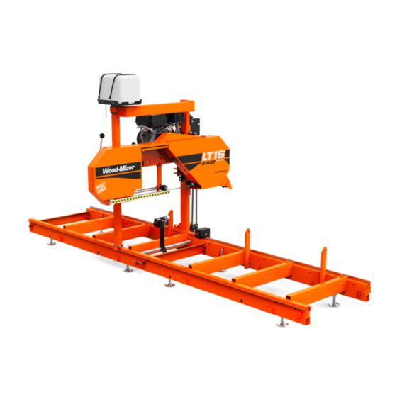
Introduction Wood-Mizer Locations Specifications Model: LT15S Rev. A1.00+ Dimensions: Metric Length: 161" 4.09m Width: 6'-3" 1.89m Height (Ground To Mast): 5'-4" 1.98m Height (Max Head Position): 6'-6" 2.0m Bed Height (Ground To Bed): 11" 0.27m Blade Length: 158" 4.01m Weights:... -
Page 9: Customer And Sawmill Identification
Wood-Mizer Limited Product Warranty Wood-Mizer LLC (“Warrantor”), an Indiana corporation with its principal place of business at 8180 West Tenth Street, Indianapolis, IN 46214-2400 USA, warrants to the purchaser (“Purchaser”) that for the time periods specifically stated herein and subject to the terms, conditions and limitations stated herein, the equipment manufactured by the Warrantor... - Page 10 Introduction Warranty stated herein, the equipment is installed, operated and maintained in accordance with the instructions provided by Warrantor. LENGTH OF WARRANTY PRODUCT MODEL CLASS EFFECTIVE DATE NON USA USA & CANADA & CANADA Portable Sawmills, Resaws, LT, LX, HR, EG Two years One year Edgers...
- Page 11 This warranty cannot be amended, except in writing, which refers to this warranty that is signed by both Warrantor and Purchaser. © 2018 Wood-Mizer LLC – 8180 West 10 Street, Indianapolis, IN 46214...
-
Page 12: Safety
The procedures listed in this manual may not include all ANSI, OSHA, or locally required safety procedures. It is the owner/operator’s respon- sibility and not Wood-Mizer Products to ensure all operators are properly trained and informed of all safety protocols. Owner/Operators are responsible for following all safety procedures when operating and performing mainte- nance to the Sawmill. - Page 13 Wood-Mizer sawmill. All Wood-Mizer mill owners are encouraged to become thoroughly familiar with these applicable laws and comply with them fully while using the mill.
- Page 14 Failure to follow this may result in serious injury. WARNING! Use ONLY water and Wood-Mizer Lube Additive with the water lube accessory. Never use flam- mable fuels or liquids such as diesel fuel. If these types of liquids are necessary to clean the blade, remove it and clean with a rag.
- Page 15 Safety Safety Instructions Be sure the blade housing and pulley covers are in place and secure. Use the safety retainer pin and cable to fasten blade hous- ing covers. WARNING! Do not operate the sawmill with- out the bed end retaining brackets properly installed;...
- Page 16 Safety Safety Instructions WARNING! Do not for any reason adjust the engine drive belt with the engine running. Doing so may result in serious injury. WARNING! Always keep clear of exiting sawdust. Keep hands, feet and any other objects away from the sawdust chute when operating sawmill. Failure to follow this may result in serious injury.
-
Page 17: Sawmill Assembly
Sawmill Assembly Unpacking SECTION 3 SAWMILL ASSEMBLY Unpacking 1. Cut open the plastic shipping shroud; remove and discard. IMPORTANT! Wear safety goggles; some shipping straps are under pressure and may spring out when cut. 2. Cut the shipping straps holding the bed sections to the pallet. 3. - Page 18 Sawmill Assembly Unpacking See Figure 3-2. . 150209-6 FIG. 3-2 8. Remove the bolt for the hold-down bracket for the right side of the mast; do not remove the bracket at this time. See Figure 3-3. ONLY Remove bolt 150209-8 FIG.
-
Page 19: Leg Assembly
Sawmill Assembly Leg Assembly See Figure 3-4. Shipping bolts (x4) Shipping strap (x2) FIG. 3-4 NOTE: Bed sections weight approximately 160 lbs. Use at least two people to move them. 12. Set the bed sections on a level surface. Leg Assembly 1. -
Page 20: Bed Section Assembly
Sawmill Assembly Bed Section Assembly See Figure 3-5. Plate Square Nut Hex Nut 150228-1B FIG. 3-5 7. Install all the legs; adjust the nuts as necessary to level the bed. 8. Use a 1 1/4” wrench to turn the hex nut and adjust each leg until the top of the leg is approxi- mately 1”... - Page 21 Sawmill Assembly Bed Section Assembly See Figure 3-7. Align top bed tube surfaces 1/2-13 Nylon Lock Nut (4) 1/2-13 x 5" Hex Head Bolt (4) 150070-1C FIG. 3-7 IMPORTANT! Make sure the top surfaces of the outer side of the bed sections are aligned.
-
Page 22: Clamp Assembly
Sawmill Assembly Clamp Assembly 4. Install the bed end retaining brackets to BOTH ENDS of the bed frame, on the same side as the roller carriage. WARNING! Do not operate the sawmill without the bed end retaining brackets properly installed; the saw head may to fall from the log bed. Failure to follow this may result in serious injury or death. -
Page 23: Saw Carriage Assembly
Sawmill Assembly Saw Carriage Assembly Saw Carriage Assembly The saw carriage is equipped with two lock pins at the bottom of the mast near the track rollers. These pins can be adjusted to two different positions: Operation position. This position allows the pins to catch the bottom of the track rail, preventing the saw head from tilting and disengaging the bed frame. -
Page 24: Miscellaneous
Sawmill Assembly Miscellaneous 6. On the middle track cover, soak the felt wiper with Dexron III transmission fluid, 10W30 motor oil, or 3-in-1 turbine oil. 7. Use the bolts and washers located on the inside faces of the roller housings to attach the middle track cover. - Page 25 Sawmill Assembly Miscellaneous See Figure 3-13. Disassemble sawdust deflector from shipping position and reinstall for operation. 150138-2 FIG. 3-13 Route the water lube hose on to the spout of the water container. See Figure 3-14. Turn valve counterclockwise to open; Clockwise to close 3H0129 FIG.
-
Page 26: Sawmill Setup
Sawmill Setup Sawmill Setup SECTION 4 SAWMILL SETUP Sawmill Setup NOTE: The following setup procedure should be performed whenever the sawmill is moved or reassembled. If sawing problems occur and misalignment is suspected, See SECTION 8 complete alignment instructions. See SECTION 3 for sawmill assembly instructions. -
Page 27: Carriage Side Adjustment
Sawmill Setup Carriage Side Adjustment 9. Measure the distance from the bed rail to the bottom of the blade near the outside blade guide. When the blade is parallel to the bed, it will measure the same distance from the bed rail at the inside and outside of the saw head. -
Page 28: Carriage Locking Pins
Sawmill Setup Carriage Locking Pins See Figure 4-3. Carriage Roller Side Roller Adjust in and out from the rail by turning the cammed shaft 150210-39 FIG. 4-3 NOTE: Do not overtighten! Roller bearings should turn freely. Carriage Locking Pins Prior to mill operation, make sure both lock pins are in the operation position (lock pins seated in lower notches of pin rest brackets). -
Page 29: Tensioning The Blade
Sawmill Setup Tensioning The Blade 1. Open both blade housing covers. 2. Turn the blade tension handle until the wheel is pulled in and the blade is loose in the blade hous- ing. 3. Lift the blade out of the blade housing. 4. -
Page 30: Tracking The Blade
Sawmill Setup Tracking The Blade 1. Use the scalloped disk to turn the tensioner shaft. See Figure 4-5. . Blade Tension Handle Use scalloped disk to adjust shaft Rubber Spring Blade Tension Indicator Bolt 150139-3 Back of washer aligned with bolt head FIG. - Page 31 Sawmill Setup Tracking The Blade 6. Position 1 1/4” wide blades so the gullet is 1/8" (3.0 mm) out from the edge of the blade wheel (±1/32 [.75 mm]). See Figure 4-6. 150060 1/8” (3.0 mm) ± 1/32” (0.75 mm) 1 1/4”...
-
Page 32: Starting The Engine
Sawmill Setup Starting The Engine DANGER! Make sure all guards and covers are in place and secured before operating the sawmill. Failure to follow this may result in serious injury. Be sure the blade housing and pulley covers are in place and secure. IMPORTANT! After aligning the blade on the wheels, always double-check the blade guide spacing and location. -
Page 33: Sawmill Operation
Sawmill Operation Loading, Turning And Clamping Logs SECTION 5 SAWMILL OPERATION Loading, Turning And Clamping Logs TO LOAD LOGS 1. Start the engine and move the saw carriage to the front end of the frame. CAUTION! Before loading a log, be sure the cutting head is moved far enough forward so the log does not hit it. - Page 34 Sawmill Operation Loading, Turning And Clamping Logs 6. Use a cant hook (part number CH48) to roll the log up the ramps and onto the sawmill bed. Posi- tion the log against the side supports. NOTE: Position the log on the bed sections to maximize support of the log by the bed.
-
Page 35: Up/Down Operation
Sawmill Operation Up/Down Operation See Figure 5-2. Leveling wedge Level log so heart is same distance from bed rails at both ends 150210-20 FIG. 5-2 Up/Down Operation 1. Install a blade, if needed, and check for correct blade tension. (See Section 4.4). -
Page 36: Blade Guide Arm Operation
Sawmill Operation Blade Guide Arm Operation See Figure 5-3. Handle lock Pointer 150256-06 FIG. 5-3 CAUTION! DO NOT try to force the carriage above the 27" (68 cm) mark or below the 1" (2.54 cm) mark. Damage to the up/down system may result. Blade Guide Arm Operation 1. -
Page 37: Clutch Operation
Sawmill Operation Clutch Operation Clutch Operation 1. Clear any loose objects from the area of the blade, motor, and drive belt. 2. Make sure the clamp and side supports are adjusted below the level of your first few cuts. 3. Start the engine as instructed in the option manual. DANGER! Keep all persons out of the path of moving equipment and logs when operating sawmill or loading and turning logs. -
Page 38: Edging
Sawmill Operation Edging 9. Repeat until the first side of the log is cut as desired. 10. Set aside the usable flitches (boards with bark on one or both sides). You can edge them on the mill later. 11. Remove the wedge if it was used. 12. - Page 39 Sawmill Operation Blade Height Scale See Figure 5-5. Inch Scale Blade Height Indicator 150210-5 FIG. 5-5 THE INCH SCALE The horizontal line on the blade height indicator shows how many inches the bottom of the blade is above the bed of the mill. If you know the height of your blade at each cut, you can determine the thickness of lumber you are sawing.
-
Page 40: Water Lube Operation
15 seconds to clean the blade of sap buildup. Wipe the blade dry with a rag before storing or sharpening. For further lubrication benefits, add one 12oz. (0.35L) bottle of Wood-Mizer Lube Additive to 5 gallons (18.9 liters) of water. Wood-Mizer Lube Additive enables some difficult timbers to be cut by significantly reducing resin buildup on the blade, heat buildup, wavy cuts, and blade noise. -
Page 41: Loading & Transporting The Sawmill
Sawmill Operation Loading & Transporting the Sawmill If you are sawing in freezing temperatures, remove the water lube bottle from the sawmill when done sawing and store it in a warm place. Blow any remaining water from the water lube hose. Loading &... - Page 42 Sawmill Operation Loading & Transporting the Sawmill CAUTION! Adjust the saw head up just far enough so it will clear the sides of your truck bed when loaded. NOTE: For most pickup trucks, a minimum of 18” (460mm) between the blade and bed frame cross members should be adequate.
- Page 43 Sawmill Operation Loading & Transporting the Sawmill 12. Secure the sawmill to the truck bed to prevent the sawmill from shifting while it is being trans- ported. If the sawmill extends beyond the truck bed, attach a red warning flag to the end of the sawmill.
-
Page 44: Maintenance
Maintenance Blade Guides SECTION 6 MAINTENANCE This section lists the maintenance procedures that need to be performed. See the Maintenance chart located after this section for a complete list of maintenance proce- dures and intervals. Keep a log of machine maintenance by recording in the machine hours and the date you perform each procedure. -
Page 45: Carriage Track, Wiper & Scrapers
Maintenance Carriage Track, Wiper & Scrapers WARNING! Keep clear of exiting sawdust. Keep hands, feet and any other objects away from the sawdust chute when operating sawmill. Failure to follow this may result in serious injury. WARNING! Ensure the steel fingers inside the sawdust chute are in place before operating the sawmill. -
Page 46: Vertical Mast Rails
Maintenance Vertical Mast Rails See Figure 6-1. Track roller housing Middle track cover Track roller housing Track wipers Idle track wipers 150210-37 FIG. 6-1 Vertical Mast Rails WARNING! Before performing service near moving parts such as blades, pul- leys, motors, belts and chains, first turn the key switch to the OFF (#0) position and remove the key. -
Page 47: Blade Wheel Belts
See Table 6-2. See the table below for drive belt tension specifications for your model sawmill. Measure the belt tension with a gauge. NOTE: Wood-Mizer offers a belt tension gauge (Part No. 016309) that will let you accurately measure the belt tension. - Page 48 Maintenance Drive Belt Adjustment ADJUST THE DRIVE BELT TENSION 1. Loosen the drive belt jam and hex nuts. Turn the jam nut counterclockwise (as viewed from the top) to tighten the belt. See Figure 6-2. Belt Tension Gauge Throttle Linkage Adjustment After 4/15 Turn jam nut clockwise...
-
Page 49: Up/Down System
Maintenance Up/Down System See Figure 6-3. Drive Belt Support Bracket 150256-08 FIG. 6-3 Adjust the drive belt support as needed. 1. Loosen the adjustment bolt. 2. Position the bracket so that the prong is close to, but does not touch, the drive belt with the clutch handle engaged. - Page 50 Maintenance Up/Down System A chain tension adjustment bracket/bolt is provided on the sprocket assembly. Loosen the jam nut and tighten the adjustment bolt to pull the sprocket down and tension the chain. Retighten the jam nut and sprocket nut after tensioning the chain. See Figure 6-4.
- Page 51 Maintenance Up/Down System See Figure 6-5. Refer to the following diagram for up/down chain routing instructions. Up/Down Chain 150210-6 FIG. 6-5 See Figure 6-6. Lubricate the up/down crank handle bearings every 200 hours with a NLGI No. 2 grade lithium grease. Apply the grease to the fitting on the handle bracket tube. Up/Down Crank Handle Grease Fitting 150256-09...
-
Page 52: 6.10 Maintenance Chart
Maintenance Maintenance chart 6.10 Maintenance chart MAINTENANCE LOG MANUAL MAINTENANCE (Check Engine And Option Manuals for additional REFERENCE INTERVAL maintenance procedures) Clean sawdust from, battery box lid & track cover See Section 6.3 8 hours Clean and lubricate track See Section 6.4 8 hours Inspect lift assist cables See Section 6.9... -
Page 53: Troubleshooting Guide
Troubleshooting Guide Sawing Problems SECTION 7 TROUBLESHOOTING GUIDE Sawing Problems WARNING! Before performing service near moving parts such as blades, pul- leys, motors, belts and chains, first turn the key switch to the OFF (#0) position and remove the key. Failure to follow this may result in serious injury or death. PROBLEM CAUSE SOLUTION... - Page 54 Troubleshooting Guide Sawing Problems PROBLEM CAUSE SOLUTION Boards Thick Or Thin On Ends Stress in log which causes log After log has been squared, take Or Middle Of Board. to not lay flat on the bed. equal cuts off opposing sides. Take a board off the top.
-
Page 55: Sawmill Alignment
Sawmill Alignment Routine Alignment Procedure SECTION 8 SAWMILL ALIGNMENT Two alignment procedures are available to realign the sawmill if necessary. The Routine Align- ment instructions should be performed as necessary to solve sawing problems not related to blade performance. The Complete Alignment procedure should be performed approximately every 1500 hours of operation (sooner if you regularly transport the sawmill over rough terrain). -
Page 56: Blade Guide Arm Alignment
Sawmill Alignment Blade Guide Arm Alignment adjusted parallel to the bed rail, check the space between the uppermost mast bearing and mast rail. Adjust as necessary so the space is 1/32” - 1/16” (0.8 - 1.6mm). Loosen Bearing Nut And Adjust Space from Mast to 1/32"... - Page 57 Sawmill Alignment Blade Guide Arm Alignment 1. Adjust the blade guide arm out to 1/2" (13 mm) from fully open. See Figure 8-2. Use the inside top and bottom screws to adjust the arm up until the slide pad touches the saw head brace tube. Tighten the jam nuts. 150210-7 Adjust inside top Adjust outside top...
-
Page 58: Blade Guide Vertical Tilt Alignment
Sawmill Alignment Blade Guide Vertical Tilt Alignment See Figure 8-3. With the blade guide arm still all the way in toward the other blade guide, tighten all the side screws until they touch the arm. Back the screws off 1/4 turn and tighten the jam nuts. Blade Guide Arm Parallel to Blade Adjust side screws to 150036B... -
Page 59: Blade Guide Horizontal Tilt Adjustment
Sawmill Alignment Blade Guide Horizontal Tilt Adjustment See Figure 8-4. Clip tool to blade SM0069B FIG. 8-4 3. Move the carriage so that the front end of the tool is positioned above the bed rail. Measure the distance from the bed rail to the bottom edge of the tool. 4. - Page 60 Sawmill Alignment Blade Guide Horizontal Tilt Adjustment 9. Remove the clip from the blade guide alignment tool. Place the tool against the face of the outer blade guide roller. See Figure 8-6. Blade Guide 3H0802-5B Alignment Tool FIG. 8-6 10. Measure between the back edge of the blade and the tool at the end closest to the inner blade guide ("B").
-
Page 61: Blade Guide Flange Spacing
Sawmill Alignment Blade Guide Flange Spacing NOTE: Once the blade guides have been adjusted, any cutting variances are most likely caused by the blade. See Blade Handbook, Form #600. Blade Guide Flange Spacing Each blade guide must be adjusted so the roller flange is the correct distance from the back edge of the blade. -
Page 62: Blade Height Scale Adjustment
Sawmill Alignment Blade Height Scale Adjustment 3. Place a square against the face of the side support. The side support should be square or slightly tilted forward 1/32" (0.8 mm). Adjust the vertical tilt of the side support if necessary. See Figure 8-9. -
Page 63: Complete Alignment Procedure
Sawmill Alignment Frame Setup Loosen indicator bracket mounting 150210-8 FIG. 8-10 Complete Alignment Procedure Frame Setup Before performing the following alignment procedures, setup the mill on firm, level ground. Level the frame and adjust the saw head as described in Section 4.1 Sawmill Setup. -
Page 64: Blade Wheel Alignment
Sawmill Alignment Blade Wheel Alignment 7. Start the engine. 8. Engage the blade, rotating the blade until the blade positions itself on the wheels. WARNING! Do not spin the blade wheels by hand. Spinning the blade wheels by hand may result in serious injury. 9. - Page 65 Sawmill Alignment Blade Wheel Alignment See Figure 8-12. Use the vertical adjustment screws to adjust the drive-side blade wheel. 150210-14 Blade Guide Alignment Tool Adjust vertical adjustment screws down to tilt drive-side blade wheel up; Adjust screws up to tilt wheel down FIG.
- Page 66 Sawmill Alignment Blade Wheel Alignment See Figure 8-13. Use the vertical adjustment screws to adjust the idle-side blade wheel. Adjust vertical adjustment screws up to tilt idle-side blade wheel down; Adjust screws down to tilt wheel up 150210-9 FIG. 8-13 To tilt the wheel up, loosen the bottom adjustment screw one quarter turn.
- Page 67 Sawmill Alignment Blade Wheel Alignment See Figure 8-14. The horizontal tilt of the blade wheel should be adjusted so that the gullet of an 1-1/4" blade is 1/8" (3 mm) out from the front edge of the wheel (±1/32 [0.75 mm]). 150060 1/8”...
-
Page 68: Blade Guide Installation
Blade Guide Installation Each Wood-Mizer sawmill has two blade guide assemblies that help the blade maintain a straight cut. The two blade guide assemblies are positioned on the saw head to guide the blade on each side of the material being cut. -
Page 69: Blade Guide Arm Alignment
Sawmill Alignment Blade Guide Arm Alignment See Figure 8-17. Tighten the two previously-loosened tilt adjustment screws to secure the blade guide assembly. Top Vertical Adjustment Jam Nut Tilt Adjustment Screws (4) Blade Guide Shaft Centered Roller Flange In Block Bottom Vertical Adjustment Jam Nut 3H0802-15 FIG. -
Page 70: Blade Guide Deflection
Sawmill Alignment Blade Guide Deflection 1. Adjust the blade guide arm out to 1/2" (13 mm) from fully open. 2. Adjust the blade guide arm in all the way toward the other blade guide. 3. Use the outside top and bottom screws to adjust the arm up until the slide pad touches the saw head brace tube. -
Page 71: Blade Guide Vertical Tilt Alignment
Sawmill Alignment Blade Guide Vertical Tilt Alignment 1. Raise the saw head until the blade is 15" (375 mm) above a bed rail. Measure the actual distance with a tape from the top of the rail to the bottom of the blade. 2. - Page 72 Sawmill Alignment Blade Guide Vertical Tilt Alignment See Figure 8-21. Clip tool to blade SM0069B FIG. 8-21 3. Move the carriage so that the front end of the tool is positioned above the bed rail. Measure the distance from the bed rail to the bottom edge of the tool. 4.
-
Page 73: Blade Guide Horizontal Tilt Adjustment
Sawmill Alignment Blade Guide Horizontal Tilt Adjustment Blade Guide Horizontal Tilt Adjustment If the blade guides are tilted in the wrong direction horizontally, the back of the blade may contact the flange as the roller is spinning down, causing it to push the blade away from the guide roller. 1. -
Page 74: Blade Guide Flange Spacing
Sawmill Alignment Blade Guide Flange Spacing See Figure 8-24. Loosen the jam nuts on the horizontal tilt adjustment screws. To tilt the roller left, loosen the right screw and tighten left screw. To tilt the roller right, loosen the left screw and tighten the right screw. -
Page 75: Side Support Alignment
Sawmill Alignment Side Support Alignment 1. Measure the distance between the flange on the outer blade guide roller to the back edge of the blade. This distance should measure 1/8" (3.0 mm). Adjust the roller back or forward if neces- sary. -
Page 76: Blade Height Scale Adjustment
Sawmill Alignment Blade Height Scale Adjustment See Figure 8-26. Loosen the top adjustment bolt, adjust the side support, and retighten the bolt.Turn the adjustment bolt counterclockwise to tilt the top of the side support forward. Side Support Adjustment Bolt 150039 FIG. - Page 77 Sawmill Alignment Blade Height Scale Adjustment See Figure 8-27. Loosen the indicator bracket mounting nut. Adjust the bracket up or down until the indicator is aligned with the correct mark on the scale (+0 -1/32 [0.8 mm]). Retighten the indi- cator mounting nut.
-
Page 78: Index
INDEX assembly maintenance bed sections blade guide log clamp blade wheel belts saw carriage carriage track/wipers drive belt mast rails miscellaneous part wear life sawdust removal blade up/down breakage, troubleshooting installation montagem tensioning pé tracking blade guide arm operation operation edging sawing chain... - Page 79 troubleshooting sawing problems turning logs up/down operation water lube operation Index doc072619...
Need help?
Do you have a question about the LT15S and is the answer not in the manual?
Questions and answers