Wood-mizer LT10 User Manual
Sawmill
Hide thumbs
Also See for LT10:
- Safety, setup, operation & maintenance manual (100 pages) ,
- Safety, setup, operation & maintenance manual (65 pages) ,
- User manual (94 pages)
Table of Contents
Advertisement
Advertisement
Table of Contents

Subscribe to Our Youtube Channel
Related Manuals for Wood-mizer LT10


Summary of Contents for Wood-mizer LT10
- Page 1 Table of Contents Section-Page Table of Contents SW-07doc0821141...
- Page 3 Wood-Mizer ® Sawmill Safety, Setup, Operation & Maintenance Manual LT10S3 E7,5S rev. A5.02 Safety is our #1 concern! Read and understand all safety information and instructions before oper- ating, setting up or maintaining this machine. December 2006 Form #794 This is the original language...
-
Page 4: Table Of Contents
1.13 Overall Dimensions ................1-18 1.14 Components..................1-19 SECTION 2 SAWMILL ASSEMBLY Mounting Parts of LT10 Sawmills with Electric Motors .......2-1 Parts Specifications Specifications of Fasteners Tools Necessary for Assembling the Sawmill Unpacking the Sawmill ................2-5 Bed Frame Assembly ................2-6 Frame Leg Adjustment .................2-12 Saw Head Assembly................2-13... - Page 5 Table of Contents Section-Page Tensioning The Blade................3-10 Tracking The Blade ................3-11 Starting The Motor ................3-12 Loading, Turning, And Clamping Logs ..........3-13 Manual Up/Down Operation ..............3-15 Up/Down Operation (Option with Electrical Up/Down System)..3-16 Blade Guide Arm Operation..............3-17 3.10 Blade Drive Operation................3-18 3.11 Feed Operation ..................3-19 3.12...
- Page 6 Table of Contents Section-Page 6.14 Safety Handle Linkage Adjustment............6-18 6.15 Track Roller Distance Adjustment ............6-19 SECTION 7 MOTOR BRAKE Maintenance/repair .................7-1 Wear of spring − applied brakes Inspections Maintenance intervals Maintenance ...................7-2 Checking the rotor thickness Check air gap SW-07doc082114Table of Contents...
- Page 7 Sawmill and Customer Identification Each Wood-Mizer LT10 sawmill is identified with a revision and VIN numbers. E7,5 LT10 Type Motor/Engine Bed Frame Type Basic Sawmill I.D. Revision Number Minor ”Revision” Major “Revision” Code Code VIN N EVISION AND UMBERS See the chart for VIN description.
- Page 8 Customer No. Type VIN No. Revision No. IIMPORTANT! Read the entire Operator's Manual before operating the sawmill. Take notice of all safety warnings throughout this manual and those posted on the machine. Keep this manual with this machine at all times, regardless of ownership.
-
Page 9: General Contact Information
General Contact Information Getting Service Wood-Mizer is committed to providing you with the latest technology, best quality and strongest customer service available on the market today. We continually evaluate our customers’ needs to ensure we’re meeting current wood-processing demands. Your comments and suggestions are welcome. -
Page 10: Branches & Authorized Sales Centers
Branches & Authorized Sales Centers Branches & Authorized Sales Centers EUROPE UNITED STATES European Headquarters World Headquarters Wood-Mizer Industries Sp. z o.o. Wood-Mizer LLC Nagórna 114, 62-600 Koło, Poland 8180 West 10th Street Tel.: +48-63-26-26-000 Indianapolis,Indiana 46214-2400, Fax: +48-63-27-22-327 www.woodmizer.eu Tel.: +1-317-271-1542... - Page 11 Branches & Authorized Sales Centers CROATIA Krešimir Pregernik ITALY Pasquale Felice SERBIA Dragan Markov Pregimex d.o.o. Wood-Mizer Italia Srl Wood-Mizer Balkan d.o.o. S. Batušiæa 31, 10090 Zagreb Cda. Capoiaccio SN Svetosavska GA 3/3; P. Fah 25 Tel.:/Fax: +3851-38-94-668 86012 Cercemaggiore 23 300 Kikinda Krešimir Pregernik...
- Page 12 Tel.: +49-5883-9880-12 GSM: +49-17-298-55-892 e-mail: KLongmuss@woodmizer.de Subagents: ROMANIA Adrian Echert Regional Manager - Asia DENMARK Brian Jensen SC WOOD-MIZER RO SRL Wood-Mizer Asia Pte Ltd. Arnborgvej 9, 7330 Brande- Fasterholt TRANSILVANIEI Nr. 5 James Wong Tel.: +45-971-88-265 Sibiu, Cisnadie 555300...
-
Page 13: Safety
It is always the owner's responsibility to comply with all applicable federal, state and local laws, rules and regulations regarding the ownership, operation and towing of your Wood-Mizer sawmill. All Wood-Mizer mill owners are encouraged to become thoroughly familiar with these applicable laws and comply with them fully while using the mill. -
Page 14: Blade Handling
Safety Blade Handling Blade Handling DANGER! Always disengage the blade and shut off the sawmill engine before changing the blade. Failure to do so will result in serious injury. WARNING! Always wear gloves and eye protection when handling bandsaw blades. Changing blades is safest when done by one person! Keep all other persons away from area when coiling, carrying or changing a blade. - Page 15 Safety Sawmill Operation WARNING! Always wear eye, ear, respiration and foot protection as well as safety clothing when operating the sawmill. Failure to do so may result in serious injury. WARNING! Secure all loose clothing and jewelry before operating the sawmill.
-
Page 16: Sawmill Maintenance
Safety Sawmill Maintenance Sawmill Maintenance CAUTION! Reinstall the track wiper so that it lightly touches the track bar. If the wiper presses too firmly against the bar, it can cause the power feed to bind. CAUTION! Never use grease on the mast rails as it will collect sawdust. -
Page 17: Safety Instructions
It is always the owner's responsibility to comply with all applicable federal, state and local laws, rules and regulations regarding the ownership and operation of your Wood-Mizer sawmill. All Wood-Mizer sawmill owners are encouraged to become thoroughly familiar with these applicable laws and comply with them fully while using the machine. -
Page 18: Wear Safety Clothing
Safety Wear Safety Clothing Wear Safety Clothing WARNING! Secure all loose clothing and jewelry before operating the sawmill. Failure to do so may result in serious injury or death. WARNING! Always wear gloves and eye protection when handling bandsaw blades. Changing blades is safest when done by one person! Keep all other persons away from area when coiling, carrying or changing a blade. -
Page 19: Check Sawmill Before Operation
Safety Check sawmill Before Operation Check sawmill Before Operation DANGER! Make sure all guards and covers are in place and secured before operating the sawmill. Failure to do so may result in serious injury. Keep Persons Away DANGER! Keep all persons out of the path of moving equipment and lumber when operating the sawmill. -
Page 20: Keep Hands Away
Safety Keep Hands Away Keep Hands Away DANGER! Always shut off the blade motor before changing the blade. Failure to do so will result in serious injury. DANGER! Motor components can become very hot during operation. Avoid contact with any part of a hot motor. Contact with hot motor components can cause serious burns. -
Page 21: Use Proper Maintenance Procedures
Safety Use Proper Maintenance Procedures Use Proper Maintenance Procedures DANGER! Make sure all electrical installation, service and/or maintenance work is performed by a qualified electrician and is in accordance with applicable electrical codes. DANGER! Hazardous voltage inside the electric boxes and at the motor can cause shock, burns, or death. -
Page 22: Keep Safety Labels In Good Condition
If replacing a component which has a safety decal affixed to it, make sure the new component also has the safety decal affixed. See Table 1-1. Pictogram decals used to warn and inform the user about danger in the LT10. TABLE 1-1 Decal View W-M No. - Page 23 Safety Keep Safety Labels In Good Condition TABLE 1-1 099219 Blade tension. Turning the bolt clockwise will increase the blade tension and turning the bolt counterclockwise will decrease the tension. 099219 099221 CAUTION! Keep all persons a safe distance away from work area when operating the machine.
- Page 24 Safety Keep Safety Labels In Good Condition TABLE 1-1 096321 Blade movement direction S12004G CAUTION! Always wear safety goggles when operating the sawmill! S12005G CAUTION! Always wear protective ear muffs when operating the sawmill! 501465 CAUTION! Always wear safety boots when operating the sawmill! 501467 Lubrication Point...
- Page 25 Safety Keep Safety Labels In Good Condition TABLE 1-1 P11789 Aligning the blade on the wheels 099226 Power feed system engagement 099226 092597 Setting the blade tension indicator 092597 P85070 CE safety certification 099401 Russian safety certification 099401 Safety 15doc082114 1-13...
-
Page 26: Belt Sizes
To insure proper blade tracking, use Goodyear, Dayco Super II, or Browning belts only. Blade Sizes See Table 1-3. Wood-Mizer TRU•SHARP™ offers three types of blades to provide efficient sawing for all models of sawmills. The engine/motor size of your sawmill and the type of wood you saw 1-14... -
Page 27: Cutting Capacity
LT10 sawmill works with a blade 4.01 m length. See The Blade Handbook for blade hook angle, tooth height, and tooth set specifications. Cutting Capacity See Table 1-4. The log size capacities of the LT10 sawmills are listed below. Max. Diameter Max. Length LT10 S3... -
Page 28: Noise Level
Safety Noise Level 1.11 Noise Level See Table 1-6. The average level of noise is given in table below Noise Level LT10E7,5 83,3 dB (A) TABLE 1-6 1. The noise level measurement was taken in accordance with PN-EN ISO 3746 Standard. The noise exposure level given above concerns an 8-hour work day. -
Page 29: Sust Extractor Specifications
Safety Sust Extractor Specifications 1.12 Sust Extractor Specifications See Table 1-1. Specifications of the dust extractors used on the resaw for each saw head are listed below. Airflow 1200 m 3937ft Inlet diameter 100 mm (5.9”) Motor power 1,5 kW Number of sacks 1 pcs Sack capacity... -
Page 30: Overall Dimensions
Safety Overall Dimensions 1.13 Overall Dimensions See Figure 1-2. The overall dimensions of the LT10 sawmills are shown below. 2051 2151 10_002e FIG. 1-1 1-18 15doc082114 Safety... -
Page 31: Components
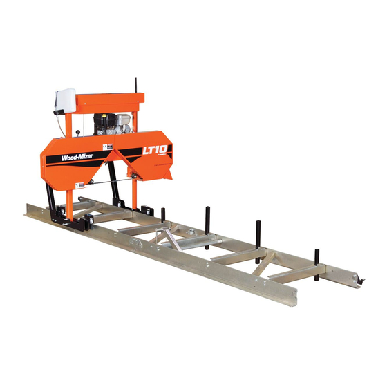
Safety Components 1.14 Components See Figure 1-3. The major components of the Wood-Mizer LT10 are shown below. Blade Drive Motor Water Tank Electric Box Blade Tensioner Blade Guide Arm Handle Sawmill Frame Up/Down Crank Handle 10_001_F Clamp FIG. 1-2 Safety... -
Page 32: Sawmill Assembly
SAWMILL ASSEMBLY Mounting Parts of LT10 Sawmills with Electric Motors SECTION 2 SAWMILL ASSEMBLY Mounting Parts of LT10 Sawmills with Electric Motors 2.1.1 Parts Specifications Table 1: Sawmill Mounting Parts Fig. Wood-Mizer No. Description Qty. LT10S3 LT10S4 LT10 EC 094514 LT15 Bed Section, Complete (1.95 m) - Page 33 SAWMILL ASSEMBLY Parts Specifications Table 1: 086659-1 Frame Mounting Strap, Zinc-plated 086745 Middle Track Cover with Felt Wiper 093859 Plate, PC Guard 094250-1 Track Rail, Zinc-plated (Short) 095490-1 Auxiliary Bed Rail 100903-1 Sawdust Chute 500844-1 Bed Extension Tube, Painted 502725-1 Feed Rope Mount Front Bracket 502726-1...
-
Page 34: Specifications Of Fasteners
LTBGAT Tool, Blade, Guide, Alignment R02080 Rope 100903-1 Sawdust Chute 503768-1 Guide Upright 2.1.2 Specifications of Fasteners Table 2: Wood-Mizer No. Description Qty. LT10-EC Sample designations of fasteners: M8 Nut M8x20 Bolt 8.4 Washer F81003-17 M10x35 Bolt F81030-2 M5 Nut... -
Page 35: Tools Necessary For Assembling The Sawmill
SAWMILL ASSEMBLY Tools Necessary for Assembling the Sawmill Table 2: F81037-1 M20 Nut F81032-1 M8 Nut F81002-20 M8x16 Bolt F81002-23 M8x100 Bolt F81059-2 Washer, 21 Flat Zinc F81053-1 Washer, 6.4 Flat Zinc 095919 Cap, A 50x30 Black 097480 Pipe Cap 40x40x(3-4) F81056-1 13 Flat Washer F81034-1... -
Page 36: Unpacking The Sawmill
SAWMILL ASSEMBLY Unpacking the Sawmill Unpacking the Sawmill See Figure 2-1. FIG. 2-1 1. Cut the bands holding the components together. 2. Remove frame parts from the pallet. 3. Remove up/down crank from the saw head, slide on the up/down handle and secure with the pin (Part No F81045-1). -
Page 37: Bed Frame Assembly
SAWMILL ASSEMBLY Bed Frame Assembly See Figure 2-2. Locking Pin F81045-1 FIG. 2-2 4. Using the up/down crank raise the saw head. Open the box with the sawmill’s equipment. Bed Frame Assembly IMPORTANT! With all screw joints without spring lock washer or lock nylon nut, use the "LOCTITE 243"... - Page 38 SAWMILL ASSEMBLY Bed Frame Assembly See Figure 2-3. 094427-1 (LT15S3) 094696-1 (LT15M2) M10 Hex Nylon Lock Nut 10.5 Washer 150158b M10x75 Bolt FIG. 2-3 2. In case of sawmills with non-adjustable legs - Mount four (or six) legs to each bed section. Use two hex head bolts and lock nuts to secure each leg to the bed section.
- Page 39 SAWMILL ASSEMBLY Bed Frame Assembly See Figure 2-4. M10x75 Bolt 150185B 085994-1 10.5 Washer M10 Hex Nylon Lock Nut 100064-1 FIG. 2-4 3. In case of sawmills adjustable legs - Mount four (or six) leg brackets to each bed section. Use two hex head bolts and lock nuts to secure each leg bracket to the bed section.
- Page 40 SAWMILL ASSEMBLY Bed Frame Assembly See Figure 2-5. M10x120 Bolt 095742-1 085994-1 M20 Nut 150160a 21 Washer 095745-1 M10 Hex Nylon 10.5 Washer Lock Nut 086723-1 FIG. 2-5 4. Lay the frame sections end-to-end so the track portion of each section is on the same side. Slide the sections together and secure with four hex head bolts and nylon lock nuts.
- Page 41 SAWMILL ASSEMBLY Bed Frame Assembly See Figure 2-6. M10x30 Bolt M6x16 (4pcs) M10 Hex Nylon Lock 10.5 Flat Washer 10.2 Split Lock Washer M10x25 Bolt Frame Mounting Strap (086660) 150159G M12x120 Bolt (4pcs) 13 Flat Washer M12 Hex Nylon Lock FIG.
- Page 42 SAWMILL ASSEMBLY Bed Frame Assembly See Figure 2-7. 10.2 Split Lock M12 Hex Nylon Washer Lock Nut M10x75 Bolt 086659-1 10.5 Washer 094250-1 M10x30 Bolt 13 Flat Washer M12x120 Bolt M10 Hex Nylon Lock Nut FIG. 2-7 7. Assemble a log clamp to a bed rail on each bed section using the existing hex head bolts and nylon lock nuts. 8.
-
Page 43: Frame Leg Adjustment
SAWMILL ASSEMBLY Frame Leg Adjustment See Figure 2-8. 150157b 100076-1 Bolt M12 Nut 085981-1 13 Washer 014972 097224 M12x140 Bolt FIG. 2-8 Frame Leg Adjustment 1. Place a foot plate under each bed leg. 2. Using an appropriate wrench, adjust each leg so that the nut is approximately 25mm below the top of the bed tube SAWMILL ASSEMBLY 15doc082114... -
Page 44: Saw Head Assembly
SAWMILL ASSEMBLY Saw Head Assembly See Figure 2-9. (1") 25mm 150108b Foot Plate FIG. 2-9 CAUTION! The top of the leg should not be higher than the top surface of the bed rail. Saw Head Assembly 1. Using a forklift truck or a winch with lifting capacity of minimum 500 kg, carefully lift the saw head and set it aside. - Page 45 SAWMILL ASSEMBLY Saw Head Assembly See Figure 2-10. 500kg FIG. 2-10 1. Position the saw head at the end of the bed frame assembly. Carefully slide the saw head rollers onto the bed frame track. Keep the saw head square to the bed to avoid jamming the track rollers. WARNING! When setting the saw head on the bed frame, use extreme care and keep all persons at a safe distance.
- Page 46 SAWMILL ASSEMBLY Saw Head Assembly See Figure 2-11. M8x12 Bolt Track Wiper (086322) 10_054_A M8x12 Bolt Track Wiper (086322) 8.4 Washer M8x12 Bolt FIG. 2-11 NOTE: Before installing the track cover and the remaining felt wipers, soak the felt strips with lubricating fluid (e.g.
- Page 47 SAWMILL ASSEMBLY Saw Head Assembly See Figure 2-12. M8x16 Bolt 8.4 Washer 10_052c 100903-1 FIG. 2-12 4. Install the operator guard. See Figure 2-13. M8x16 Bolt M8x25 Bolt Nut, M8 Hex Nylon Zinc Lock 8.4 Washer 10_055a M10x50 Bolt Guard (093859) 10.5 Washer M8x20 Bolt FIG.
- Page 48 SAWMILL ASSEMBLY Saw Head Assembly 5. Install the blade guides. See Figure 2-14. Blade Guide (094682) Blade Guide (094683) M10x1x25 Bolt Nut, M10x1 Thin (8) Screw, M10x1x20 (7) FIG. 2-14 6. Install the power cord bracket. 2-17 15doc082114 SAWMILL ASSEMBLY...
-
Page 49: Log Loading Ramp (Option)
SAWMILL ASSEMBLY Log Loading Ramp (Option) See Figure 2-15. Holder, Plastic Cable Tie Screw, M4x16 (F81082-1) Power Cord Bracket 086132-1 M4 Nut 4.3 Washer FIG. 2-15 Log Loading Ramp (Option) To install the log loading ramp, mount the ramp bracket (1) to the bed frame section tube using two bolts (2), four washers (3) and two nuts (4) in the place shown below. - Page 50 SAWMILL ASSEMBLY Log Loading Ramp (Option) See Figure 2-16. 150232a FIG. 2-16 2-19 15doc082114 SAWMILL ASSEMBLY...
-
Page 51: Setup & Operation
Setup & Operation Sawmill Setup SECTION 3 SETUP & OPERATION Sawmill Setup IMPORTANT! Before starting to use the sawmill you have to meet the following conditions: Set up the sawmill on firm, level ground and level the sawmill. Secure the sawmill to the ... - Page 52 Setup & Operation Sawmill Setup the motor body (fan guard). If the rotation direction is incorrect, invert the phases in the phase inverter in the power socket (electric box). Setting the phases in the phase inverter correctly will ensure correct rotation directions of all sawmill motors.
- Page 53 Setup & Operation Sawmill Setup See Figure 3-1. Equal height Equal height object object Measure distance Measure distance between string between string and bed rails and bed rails 150115c Equal height Equal height String Across String across object object Bed Rails bed rails FIG.
- Page 54 Setup & Operation Sawmill Setup saw head adjustment nuts to move the outside of the saw head up or down. Lock Nut Saw Head Adjustment Nuts (2) 150116D Roller Bracket Mast Retaining Mounting Bolt (4) Bracket Mounting Bolts (2) Scraper Mounting Bolts (2) FIG.
- Page 55 Setup & Operation Sawmill Setup See Figure 3-3. Slide Pad Adjustment Nuts FIG. 3-3 10. Check the vertical alignment of each blade wheel using the blade guide alignment tool. Attach the tool to the blade near the outer blade guide. Be sure the tool does not rest on a tooth ...
- Page 56 Setup & Operation Sawmill Setup Move the saw head so the front end of the tool is positioned over the first bed rail. Measure from the bottom of the tool to the top surface of the bed rail. Move the saw head so the rear of the tool is positioned over the bed rail. Again, measure from ...
- Page 57 Setup & Operation Sawmill Setup See Figure 3-6. To tilt the drive-side blade wheel down, loosen the top adjustment screw, loosen the nut on the bottom adjustment screw and tighten the bottom screw. Tighten the top and bottom nuts. To tilt the wheel up, loosen the bottom adjustment screw, loosen the nut on the top adjustment screw and tighten the top screw.
- Page 58 Setup & Operation Sawmill Setup guides and adjust if necessary. 14. Install the blade height scale. To do that, first measure the distance from the bottom edge on a down-set tooth of the blade to the top of the bed rail. Then stick the blade height scale on the mounting bracket so that it indicates the true distance from the blade to the bed.
-
Page 59: Replacing The Blade
Setup & Operation Replacing The Blade 16. Adjust the cam engaging the limit switch as well as the saw head stop bolt so that the saw head stops moving at its lower travel limit, i.e. at the height of 25 mm above the bed. See Figure 3-8. -
Page 60: Tensioning The Blade
Setup & Operation Tensioning The Blade Open the blade housing cover. Turn the blade tension handle to release the blade tension until the wheel is pulled in and the blade is lying loose in the blade housing. Lift the blade out of the blade housing. -
Page 61: Tracking The Blade
Setup & Operation Tracking The Blade See Table 3-2. The recommended tension for different blades is shown below. Blade Type Blade Dimensions Tension Range Width (mm) Height (mm) 1.07 1015-1088 70-75 1.14 1088-1160 75-80 2735 1.07 1160-1233 80-85 TABLE 3-2 CAUTION! Release the blade tension when the resaw is not in use (for example at the end of a shift). -
Page 62: Starting The Motor
Setup & Operation Starting The Motor See Figure 3-11. To adjust where the blade travels on the blade wheels, use the cant control bolt. Cant Control Bolt 15B017_D FIG. 3-11 If the blade is too far out, back the blade onto the wheel by turning the cant control counterclockwise. If the blade is too far in, turn the cant control clockwise until the gullet of the blade is the correct distance from the front edge of the wheel. -
Page 63: Loading, Turning, And Clamping Logs
Setup & Operation Loading, Turning, And Clamping Logs motors. DANGER! Make sure all guards and covers are in place and secured/closed before operating the sawmill. Failure to do so may result in serious injury. DANGER! Always be sure the blade is disengaged and all persons are out of the path of the blade before starting the engine or motor. - Page 64 Setup & Operation Loading, Turning, And Clamping Logs 1. Position the clamps against the log, far enough down so they are below your cuts on a given side of the log. Using the clamp handles move the log firmly against the side supports. See Figure 3-12.
-
Page 65: Manual Up/Down Operation
Setup & Operation Manual Up/Down Operation To Level A Tapered Log Use shims or the optional wedge to raise either end of a tapered log, if desired. Shim one end of the log until the heart of the log measures the same distance from the bed rails at each end of the log. -
Page 66: Up/Down Operation (Option With Electrical Up/Down System)
Setup & Operation Up/Down Operation (Option with Electrical Up/Down System) See Figure 3-15. Use the up/down crank to raise or lower the cutting head. To raise the saw head turn the crank handle clockwise; to lower – turn the crank handle counterclockwise. Pull the handle grip to engage the up/down drive FIG. -
Page 67: Blade Guide Arm Operation
Setup & Operation Blade Guide Arm Operation See Figure 3-16. Use the up and down buttons shown below to raise or lower the cutting head. To raise the saw head press up button. To lower the saw head press down button. RYS. -
Page 68: Blade Drive Operation
Setup & Operation Blade Drive Operation See Figure 3-17. 150120 Move the handle right to move the blade arm out. Move it left to move the blade guide in. FIG. 3-17 3.10 Blade Drive Operation IMPORTANT! When starting the machine for the first time, check that main motor rotation direction is as indicated by the arrow located on the motor body (fan guard). -
Page 69: Feed Operation
Setup & Operation Feed Operation 3. Turn the main switch on the electrical box to the ON position, and check if the red safety button is released. 4. Press AND HOLD the safety handle on the control box. NOTE: If the safety handle is released, the blade disengages and stops. -
Page 70: Cutting The Log
3.16. 3.12 Cutting The Log The following steps guide you through normal operation of the Wood-Mizer sawmill. 1. Once the log is placed where you want it and clamped firmly, position the blade close to the end of the log. -
Page 71: Edging
Edging 3.13 Edging The following steps guide you through edging boards on the Wood-Mizer sawmill. 1. Raise the side supports to 1/2 the height of the flitches, or the boards that need to be edged. 2. Stack the flitches on edge against the side supports. - Page 72 Setup & Operation Blade Height Scale The Scale The horizontal red line on the blade height indicator shows how many centimeters the bottom of the blade is above the bed of the mill. If you know the height of your blade at each cut, you can determine the thickness of lumber you are sawing.
-
Page 73: Water Lube Operation
Setup & Operation Water Lube Operation 3.15 Water Lube Operation The Water Lube System keeps the blade clean. Water flows from a 5 liter bottle through a hose to the blade guide where the blade enters the log. A valve in the bottle cap controls the amount of water flow. -
Page 74: Transporting The Sawmill
Setup & Operation Transporting the Sawmill See Figure 3-21. Open the valve on the water bottle to start water flow on the blade. To close turn valve clockwise; to open turn valve counterclockwise. FIG. 3-21 Not all types of wood require the use of the Water Lube System. When it is needed, use just enough water to keep the blade clean. - Page 75 Setup & Operation Transporting the Sawmill See Figure 3-22. 10_079 FIG. 3-22 3. Remove the leg assemblies or adjust them above the bottom of the bed frames. 4. Position the bed of the truck at the end of the frame opposite the cutting head. 5.
- Page 76 Wood-Mizer LT10 Short Interval Maintenance Schedule PROCEDURE MANUAL REFERENCE EVERY BLADE CHANGE SEE SECTION 4.2 Check Blade Guide Roller Performance SEE SECTION 4.2 Remove Excess Sawdust From Blade Wheel Housings And Sawdust Chute EVERY 8 HOURS SEE SECTION 4.3 Clean And Lubricate Track SEE SECTION 4.3...
- Page 77 WOOD-MIZER LT10 MAINTENANCE LOG PROCEDURE MANUAL TOTAL HOURS OF OPERATION REFERENCE FILL IN THE DATE AND THE MACHINE HOURS AS YOU PERFORM EACH PROCEDURE. A SHADED BOX INDICATES MAINTENANCE IS NOT NEEDED AT THIS TIME. 50 HRS 100 HRS 150 HRS...
- Page 78 WOOD-MIZER LT10 MAINTENANCE LOG PROCEDURE MANUAL TOTAL HOURS OF OPERATION REFERENCE FILL IN THE DATE AND THE MACHINE HOURS AS YOU PERFORM EACH PROCEDURE. A SHADED BOX INDICATES MAINTENANCE IS NOT NEEDED AT THIS TIME. 1050 HRS 1100 HRS 1150 HRS...
- Page 79 WOOD-MIZER LT10 MAINTENANCE LOG PROCEDURE MANUAL TOTAL HOURS OF OPERATION REFERENCE FILL IN THE DATE AND THE MACHINE HOURS AS YOU PERFORM EACH PROCEDURE. A SHADED BOX INDICATES MAINTENANCE IS NOT NEEDED AT THIS TIME. 2050 HRS 2100 HRS 2150 HRS...
-
Page 80: Maintenance
Wear Life SECTION 4 MAINTENANCE This section lists the maintenance procedures that need to be performed on the LT10 sawmills. The Short Interval Maintenance Schedule lists procedures that need to be performed every 4, 8 or 25 hours.The Maintenance Log lists procedures that need to be performed every 50, 100, 200, or 1000 hours. -
Page 81: Vertical Mast Rails
Maintenance Vertical Mast Rails any sawdust buildup from the housings. Middle Track Cover Middle Track Cover Track Roller Track Roller Track Roller Housing Housing Housing Track Roller Housing Idle Track Wipers Idle Track Wipers 15B030B FIG. 4-1 Vertical Mast Rails Clean and lubricate the vertical mast rails every 50 hours of operation. -
Page 82: Blade Wheel Belts
Maintenance Blade Wheel Belts See Figure 4-2. Grease the blade tensioner thread 10_016_D FIG. 4-2 Blade Wheel Belts 1. Check the blade wheel belts for wear. Replace belts as necessary. Rotating the belts every 50 hours will give you longer belt life. Use only B57 belts manufactured by Goodyear or Browning. 2. -
Page 83: Miscellaneous Maintenance
Order decals from your Customer Service Representative. Safety Devices Inspection (CE version only) LT10 – Safety Devices Inspection Safety devices on the LT10 machine which must be checked before every shift: E-STOP button and its circuit inspection ... - Page 84 Maintenance Safety Devices Inspection (CE version only) Pressing the START button shouldn’t start the motor until the E-STOP button is released. Switch, Switch, Motor Emergency Start-Stop Stop Safety Handle 2. Safety handle and its circuit inspection Be sure the E-STOP button is released; ...
-
Page 85: Troubleshooting Guide
Troubleshooting Guide Sawing Problems SECTION 5 TROUBLESHOOTING GUIDE Sawing Problems PROBLEM CAUSE SOLUTION Blades Dull Quickly Dirty logs Clean or debark logs, especially on entry side of the cut. When grinding teeth, heating too much Grind just enough metal and causing teeth to soften to restore sharpness to the teeth. - Page 86 Troubleshooting Guide Sawing Problems PROBLEM CAUSE SOLUTION Boards Thick Or Thin On Stress in log which causes log to not After log has been squared, take equal Ends Or Middle Of Board lay flat on the bed cuts off opposing sides. Repeat, keeping the heart in the middle of the cant, and making it your last cut.
-
Page 87: Sawmill Alignment
Sawmill Alignment Pre-Alignment Procedures SECTION 6 SAWMILL ALIGNMENT Pre-Alignment Procedures Periodically check the sawmill alignment and adjust if necessary. This chapter explains how to align the entire sawmill. Care should be taken in performing these steps. Sawmill alignment determines the accuracy and squareness of your cuts. The sawmill alignment steps are: 1. -
Page 88: Blade Wheel Alignment
Sawmill Alignment Blade Wheel Alignment See Figure 6-1. The blade wheels should be adjusted so that the gullet of 1 1/4" blades ride 1/8" (3 mm) out from the front edge of the wheels (±1/26 [1 mm]). The gullet of 1 1/2" blades should ride 3/16"... - Page 89 Sawmill Alignment Blade Wheel Alignment See Figure 6-2. Clip tool to blade SM0069 FIG. 6-2 2. Move the saw carriage so the front end of the tool is positioned over the first bed rail. Measure from the bottom of the tool to the top surface of the bed rail. 3.
- Page 90 Sawmill Alignment Blade Wheel Alignment See Figure 6-3. Use the vertical adjustment screws to adjust the drive-side blade wheel. To tilt the wheel down, loosen the top adjustment screw half turn. Loosen the jam nut on the bottom adjustment screw and tighten the screw. Tighten the top and bottom jam nuts. To tilt the wheel up, loosen the bottom adjustment screw half turn.
- Page 91 Sawmill Alignment Blade Wheel Alignment To tilt the wheel down, loosen the top adjustment screw half turn. Loosen the jam nut on the bottom adjustment screw and tighten the screw. Tighten the top and bottom jam nuts. 150075-2_E FIG. 6-4 8.
- Page 92 Sawmill Alignment Blade Wheel Alignment See Figure 6-6. Use the cant control adjustment, shown on the figure below, to adjust the idle-side blade wheel. If the blade is too far forward on the wheel, turn the cant control counter clockwise. If it is too far back on the wheel, turn the cant control clockwise.
- Page 93 Sawmill Alignment Blade Wheel Alignment adjustment screw to move blade in on wheel. Tighten the jam nut. Adjustment Screw FIG. 6-7 11. Adjust the blade vibration damper screw. Distance from the screw to the blade should be about 1 mm. See Figure 6-8.
-
Page 94: Blade Guide Arm Alignment
Sawmill Alignment Blade Guide Arm Alignment Blade Guide Arm Alignment Before aligning the blade guide arm, track the blade on the blade wheels as described in Section 3.4. Move the cutting head so the blade is positioned over the first bed rail. Level the blade to the bed rail as shown in 3.1. -
Page 95: Aligning The Blade Guides
FIG. 6-10 Aligning The Blade Guides Each Wood-Mizer sawmill has two blade guide assemblies that help the blade maintain a straight cut. The two blade guide assemblies are positioned on the saw head to guide the blade on each side of the material being cut. -
Page 96: Blade Deflection
Sawmill Alignment Blade Deflection Blade guide alignment includes four steps: Blade Deflection, Blade Guide Vertical Tilt, Blade Guide Flange Spacing, Blade Guide Horizontal Tilt. Perform the blade guide alignment after you have aligned the blade on the wheels and adjusted the blade and blade guide arm parallel to the bed rails. -
Page 97: Blade Guide Vertical Tilt Adjustment
Sawmill Alignment Blade Guide Vertical Tilt Adjustment Blade Guide Vertical Tilt Adjustment Check that the blade guide does not tilt the blade up or down. A Blade Guide Alignment Tool (BGAT) is provided to help you measure the vertical tilt of the blade. 1. - Page 98 Sawmill Alignment Blade Guide Vertical Tilt Adjustment See Figure 6-13. Loosen jam nuts and turn screws to tilt roller up or down SM0070 FIG. 6-13 7. Move the carriage forward so the back end of the tool is over the bed rail. 8.
-
Page 99: Blade Guide Flange Spacing
Sawmill Alignment Blade Guide Flange Spacing Blade Guide Flange Spacing HINT: When adjusting blade guide flange spacing, loosen the top set screw and one side set screw only. This will insure horizontal and vertical tilt adjustments are maintained when the set screws are retightened. -
Page 100: Horizontal Tilt Adjustment
Sawmill Alignment Horizontal Tilt Adjustment 6.10 Horizontal Tilt Adjustment 1. Move the blade guide arm half way in. See Figure 6-15. FIG. 6-15 2. Place Blade Guide Alignment Tool against the face of the outer blade guide roller, as shown above. 3. -
Page 101: Blade Height Scale Adjustment
Sawmill Alignment Blade Height Scale Adjustment See Figure 6-16. Side Support Side Support Adjustment Bolt Adjustment Bolt 150039 FIG. 6-16 2. Swing a side support up so that it is vertical. 3. Pull back at the top of the support to eliminate slack as if a log were being clamped against it. 4. - Page 102 Sawmill Alignment Blade Height Scale Adjustment See Figure 6-17. Loosen the bolt FIG. 6-17 1. Move the saw head so the blade is positioned directly above one of the bed rails. Measure from the bottom edge on a down-set tooth of the blade to the top of the bed rail. 2.
-
Page 103: Motor Drive Belt Adjustment
Sawmill Alignment Motor Drive Belt Adjustment See Figure 6-18. Loosen indicator bracket mounting bolts Loosen scale bracket mounting bolt Loosen scale bracket mounting bolts FIG. 6-18 2. Move the saw head so the blade is positioned directly above one of the bed rails. Measure from the bottom edge on a down-set tooth of the blade to the top of the bed rail. -
Page 104: Safety Handle Linkage Adjustment
Sawmill Alignment Safety Handle Linkage Adjustment motor. Tighten the four motor mounting bolts. Adjustment Bolts Motor Mounting Bolts (4) FIG. 6-19 6.14 Safety Handle Linkage Adjustment See Figure 6-20. Use the adjustment nuts to adjust linkage tension so the blade stops during 6-18 15doc082114 Sawmill Alignment... -
Page 105: Track Roller Distance Adjustment
Sawmill Alignment Track Roller Distance Adjustment 8 seconds after the safety handle is released. Adjustment Nuts FIG. 6-20 6.15 Track Roller Distance Adjustment Using the screw (1), adjust the distance between the track roller (2) and the track rail (3) so that the vertical mast can move freely (see the figure below). - Page 106 Sawmill Alignment Track Roller Distance Adjustment See Figure 6-21. FIG. 6-21 6-20 15doc082114 Sawmill Alignment...
-
Page 107: Motor Brake
Motor brake Maintenance/repair SECTION 7 MOTOR BRAKE Maintenance/repair Wear of spring − applied brakes INTORQ spring − applied brakes are wear−resistant and designed for long maintenance intervals. The friction lining and the mechanical brake components are subject to function−related wear. For safe and trouble−free operation, the brake must be checked and readjusted at regular intervals, and, if necessary, be replaced. -
Page 108: Maintenance
Motor brake Maintenance Maintenance IMPORTANT! Brakes with defective armature plates, cheese head screws, springs or flanges must be replaced completely. Please observe the following for inspections and maintenance operations: Remove impurities through oil and grease using brake cleaning agents, if necessary, replace brake ... - Page 109 Motor brake Maintenance If necessary, adjust air gap to "s ". Lürated Brake Type sLürated sLümax Max. Rotor thickness Excess of the +0.1mm Service adjustment adjuster nut max. [mm] min. [mm] -0.05mm Brake permissible Emax. wear [mm] INTORQ BFK458-25 TABLE 8-1 specifications EGdoc082114...
- Page 110 EC declaration of conformity according to EC Machinery Directive 2006/42/EC Annex II, 1.A We herewith declare, Wood-Mizer Industries sp. z o.o. 114 Nagorna street, 62-600 Kolo; Poland. That the following described machine in our delivered version complies with the appropriate basic safety and health requirements of the EC Machinery Directive 2006/42/EC based on its design and type, as brought into circulation by us.
Need help?
Do you have a question about the LT10 and is the answer not in the manual?
Questions and answers