Wood-mizer LT15 Series User Manual
Hide thumbs
Also See for LT15 Series:
- Safety, setup, operation & maintenance manual (100 pages) ,
- Safety, setup, operation & maintenance manual (118 pages)
Table of Contents
Advertisement
Advertisement
Table of Contents
Troubleshooting

Related Manuals for Wood-mizer LT15 Series


Summary of Contents for Wood-mizer LT15 Series
- Page 1 Table of Contents Section-Page Table of Contents SW-07doc0127091...
- Page 3 Wood-Mizer ® Safety, Setup, Operation & Maintenance Manual LT15S3 G15 rev. C3.01 LT15M2 G15 rev. C3.01 LT15S3 D10 rev. C3.01 LT15M2 D10 rev. C3.01 Safety is our #1 concern! Read and understand all safety information and instructions before operating, setting up or maintaining this machine.
- Page 4 Sawmill and Customer Identification Each Wood-Mizer LT15 sawmill is identified with a revision and VIN numbers. LT15 Model Type Engine/Motor Base Model Configuration Revision Number Minor Revision Major Revision Code Code MODEL & REVISION NUMBERS DESCRIPTION F9 017 F9 .01 V.I.N.
- Page 5 Nagorna 114 St., at +48-63-2626000 or +48-3912-1319. From the continental U.S., call our toll-free Parts hotline at 1-800-448-7881. Please have the vehicle identification num- ber and your customer number ready when you call. Wood-Mizer will accept these meth- ods of payment:...
-
Page 6: Table Of Contents
Table of Contents Section-Page SECTION 1 SAFETY & GENERAL INFORMATION Blade Handling......................1-1 Sawmill Setup......................1-2 Sawmill Operation..................... 1-2 Sawmill Maintenance ....................1-3 Belt Sizes ........................1-7 Blade Sizes ........................ 1-8 Cutting Capacity......................1-8 Engine/Motor Specifications ..................1-9 Noise level ......................... 1-9 1.11 Overall Dimensions .................... - Page 7 Table of Contents Section-Page SECTION 4 MAINTENANCE Wear Life........................4-1 Sawdust Removal ...................... 4-1 Carriage Track & Rollers ..................4-1 Vertical Mast Rails ....................4-2 Miscellaneous Lubrication ..................4-2 Blade Wheel Belts ..................... 4-3 Miscellaneous Maintenance ..................4-3 SECTION 5 TROUBLESHOOTING GUIDE Sawing Problems .......................
-
Page 8: Safety & General Information Blade Handling
It is always the owner's responsibility to comply with all applicable federal, state and local laws, rules and regulations regarding the ownership and operation of your Wood-Mizer saw- mill. All Wood-Mizer mill owners are encouraged to become thoroughly familiar with these applica- ble laws and comply with them fully while using the mill. -
Page 9: Sawmill Setup
Safety & General Information Sawmill Setup Sawmill Setup WARNING! Do not set up the mill on ground with more than a 10 degree incline. If setup on an incline is necessary, put blocks under one side of the mill or dig out areas for the legs to keep mill level. Setting up the mill on an incline could cause it to tip over, resulting in serious personal injury. -
Page 10: Sawmill Maintenance
Safety & General Information Sawmill Maintenance WARNING! Use ONLY water with the water lube accessory. Never use flammable fuels or liquids. If these types of liquids are necessary to clean the blade, remove it and clean with a rag. Failure to do so may result in serious injury or death. - Page 11 Safety & General Information Sawmill Maintenance See Table 1-1. Pictogram decals used to warn and inform the user about danger in the LT15. TABLE 1-1 Decal View W-M No. Description 096317 CAUTION! Read thoroughly the manual before operating the machine. Observe all safety instructions and rules when operating the sawmill.
- Page 12 Safety & General Information Sawmill Maintenance TABLE 1-1 099221 CAUTION! Keep all persons a safe distance away from work area when operating the machine. 099221 086099 CAUTION! Hot elements, keep your distance! 086099 098176 CAUTION! Keep away from debarker blade! 098176 096321 Blade movement direction...
- Page 13 Safety & General Information Sawmill Maintenance TABLE 1-1 S12004G CAUTION! Always wear safety goggles when operating the sawmill! S12005G CAUTION! Always wear protective ear muffs when operating the sawmill! P11789/PL Aligning the blade on the wheels 092597 Setting the blade tension indicator 092597 P85070 CE safety certification...
-
Page 14: Belt Sizes
100583 a. Alternator charge indicator b. Up/Down Drive 100583 Belt Sizes See Table 1-2. Belt sizes for the LT15 are shown. Description Belt Size Wood-Mizer Part # Engine Drive Belt (G15, D10) BX81 097448 Blade Pulley Belts P04185 TABLE 1-2 To insure proper blade tracking, use Goodyear, Dayco Super II, or Browning belts only. -
Page 15: Blade Sizes
Blade Sizes Blade Sizes See Table 1-3. Wood-Mizer TRU•SHARP™ offers three types of blades to provide efficient saw- ing for all models of sawmills. The engine/motor size of your sawmill and the type of wood you saw should determine which blade you choose for optimum performance. -
Page 16: Engine/Motor Specifications
Safety & General Information Engine/Motor Specifications Engine/Motor Specifications See Table 1-6. The power options available for the LT15 sawmill are listed below. Engine/Motor Type Manufacturer Model No. Specifications 13HP Gasoline Kohler CH13T Spec #PA22519 398 ccm, 3600 15HP Gasoline Kohler CH15 426 ccm, 3600 10HP Diesel Engine... -
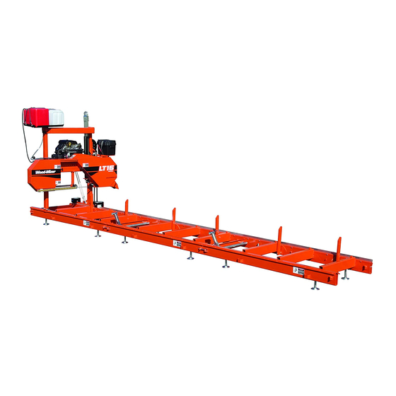
Page 17: Overall Dimensions
Safety & General Information Overall Dimensions 1.11 Overall Dimensions See Figure 1-1. The overall dimensions of the LT15 sawmills are shown below. FIG. 1-1 Safety & General Information 15doc012809 1-10... -
Page 18: Components
Safety & General Information Components See Figure 1-2. The picture below shows the operator’s position. FIG. 1-2 1.12 Components See Figure 1-3. The major components of the Wood-Mizer LT15G15 are shown below. Water Tank Engine Up/Down Drive Motor Battery Box Saw Head Up/Down &... -
Page 19: Sawmill Assembly
SAWMILL ASSEMBLY Mounting Parts of LT15 Sawmills with gasoline SECTION 2 SAWMILL ASSEMBLY Mounting Parts of LT15 Sawmills with gasoline 2.1.1 Parts specifications Table 1: Fig. Wood-Mizer Part Description Qty. Qty. LT15S3 LT15M2 095250 LT15DC Sawmill Saw Head 094697 LT15 Bed Section, Complete (2.75 m) - Page 20 SAWMILL ASSEMBLY Parts specifications Table 1: 085982-1 Log Side Support, Complete 094427-1 (LT15S3) Track Rail 094696-1 (LT15M2) R02080 Rope 8.30 7,70 086745 Middle Track Cover with Felt Wiper 086323 Left Track Wiper 086322 Right Track Wiper 086287 Plate, PC Guard 086171-1 Side Bracket 086172-1...
- Page 21 Flat Washer 17 Outrigger Leg Kit (Option) 095745-1 Leg Mounting Block 087771-1 LT15 Foot Mount Plate 2.1.2 Specifications of Fasteners Table 2: Wood-Mizer No. Description Qty. Qty. LT15S3 LT15M2 Sample designations of fasteners: M8 Nut 8,4 Washer M8x20 Bolt F81056-1...
- Page 22 SAWMILL ASSEMBLY Tools Necessary for Assembling the Sawmill Table 2: F81031-2 M6-8-B Nut F81054-1 8,4 Flat Washer F81032-2 M8 Nut F81002-5 M8x25 Bolt F81002-4 M8x20 Bolt F81055-2 10.2 Split Lock Washer 014972 33/64 x1” x 1/32 Nylon Washer F81003-11 M10x25 Bolt F81003-1 M10x20 Bolt F81034-2...
-
Page 23: Unpacking The Sawmill
SAWMILL ASSEMBLY Unpacking the Sawmill Unpacking the Sawmill FIG. 2-1 1. Cut the bands holding the components together. 2. Remove the parts arranged inside the bed section. 3. Using a forklift truck or a winch with lifting capacity of minimum 500 kg, carefully lift the saw head and set it aside. -
Page 24: Bed Frame Assembly
SAWMILL ASSEMBLY Bed Frame Assembly See Figure 2-2. FIG. 2-2 Bed Frame Assembly IMPORTANT! With all screw joints without split lock washer or lock nylon nut, use the "LOCTITE 243" (blue, of average durability, for screw joints). 1. Mount preliminarily the track rail as shown in Figure 2-3. Do not tighten the nuts. See Figure 2-3. - Page 25 SAWMILL ASSEMBLY Bed Frame Assembly 2. In case of stationary sawmills - Mount four (or six) legs to each bed section. Use two hex head bolts and lock nuts to secure each leg to the bed section. See Figure 2-4. M10x75 Bolt 085994-1 10.5 Washer...
- Page 26 SAWMILL ASSEMBLY Bed Frame Assembly 4. Lay the frame sections end-to-end so the track portion of each section is on the same side. Slide the sections together and secure with four hex head bolts and nylon lock nuts. See Figure 2-6. 10,2 Split Lock Washer M10x25 Bolt Frame Mounting...
-
Page 27: Frame Leg Adjustment
SAWMILL ASSEMBLY Frame Leg Adjustment 7. Assemble a log clamp to a bed rail on each bed section using the existing hex head bolts and nylon lock nuts. 8. Install the log side supports as shown in Figure 2-8. Tighten the nuts so that the side supports can be moved with little resistance. -
Page 28: Saw Head Assembly
SAWMILL ASSEMBLY Saw Head Assembly CAUTION! The top of the leg should not be higher than the top surface of the bed rail. Saw Head Assembly 1. Position the saw head at the end of the bed frame assembly. Carefully slide the saw head rollers onto the bed frame track. - Page 29 SAWMILL ASSEMBLY Saw Head Assembly See Figure 2-11. Spring 087301 086743-1 Cotter Pin Washer F81043-2 F81058-1 FIG. 2-11 7. Install the PC operator guard. See Figure 2-12. M8x16 Bolt Washer M10x50 Bolt 10.5 Washer FIG. 2-12 SAWMILL ASSEMBLY 15doc012809 2-11...
-
Page 30: Feed Rope Assembly
SAWMILL ASSEMBLY Feed Rope Assembly 8. Install the blade guides. See Figure 2-13. Blade Guide 094682 Blade Guide 094683 M10x1x25 Bolt M10x1 (8) M10x1x20 Washer Screw (7) FIG. 2-13 9. Adjust the saw head stop bolt, See Section 3.1, step 14.. - Page 31 SAWMILL ASSEMBLY Feed Rope Assembly 2. Tie a knot in one end of the feed rope. Slip the knotted end of the rope into the front rope mount bracket. Route the rope between the saw head and main bed frame tube. See Figure 2-15.
- Page 32 SAWMILL ASSEMBLY Feed Rope Assembly 4. Loop the rope around the feed crank spool three times and route back down to the outer v-groove roller. See Figure 2-17. 150112 FIG. 2-17 5. Route the rope around the outer groove of the v-groove roller. See Figure 2-18.
-
Page 33: Auxiliary Bed Rail
SAWMILL ASSEMBLY Auxiliary Bed Rail 6. Route the rope to the rear mounting bracket. Tie a knot in the end of the rope and insert into the mounting bracket. Position the knot in the rope so when installed to the rear bracket, the rope is tight. -
Page 34: Setup & Operation Sawmill Setup
Setup & Operation Sawmill Setup SECTION 3 SETUP & OPERATION Sawmill Setup The LT15 sawmills are only partially aligned in factory. Some assemblies need to be aligned by a user before first usage of the sawmill. Assemblies aligned in factory: Blade drive belt tension;... - Page 35 Setup & Operation Sawmill Setup See Figure 3-1. Equal height object Measure distance between string and bed rails 150115B Equal height String across object bed rails FIG. 3-1 4. Repeat the bed rail adjustment with the string at the other side of the sawmill frame. 5.
- Page 36 Setup & Operation Sawmill Setup saw head up or down. Lock Nut Saw Head Adjustment Nuts (2) Roller Bracket Mast Reaining Mounting Bolt (4) Bracket Mounting Bolts (2) Scraper Mounting Bolts (2) FIG. 3-2 See Figure 3-3. Make sure the entire face of each slide pad makes contact with the mast. Use the adjustment nuts shown below to adjust the slide pads if necessary.
- Page 37 Setup & Operation Sawmill Setup 9. Check the vertical alignment of each blade wheel using the blade guide alignment tool. Attach the tool to the blade near the outer blade guide. Be sure the tool does not rest on a tooth or burr, and is lying flat on the blade.
- Page 38 Setup & Operation Sawmill Setup To tilt wheel up, tighten top screw (loosening ealier bottom screw). To tilt wheel down, tighten bottom screw (loosening ealier top screw). FIG. 3-5 See Figure 3-6. To tilt the drive-side blade wheel down, loosen the top adjustment screw, loosen the nut on the bottom adjustment screw and tighten the bottom screw.
- Page 39 Setup & Operation Sawmill Setup Recheck the vertical alignment of each blade wheel. Readjust if necessary. 10. Adjust the spacing between each blade guide roller flange and the back of the blade. See Section 6.9. 11. Adjust the horizontal angle of the blade guides. See Section 6.10.
-
Page 40: Replacing The Blade
Setup & Operation Replacing The Blade 15. Adjust the stop bolt so that, the saw head stops 25mm above the bed. Loosen the nut and adjust the stop bolt 150172C FIG. 3-6 Replacing The Blade DANGER! Always disengage the blade and shut off the sawmill engine before changing the blade. -
Page 41: Tensioning The Blade
Setup & Operation Tensioning The Blade When installing a blade, make sure the teeth are pointing the correct direction. The teeth should be pointing toward the operator side of the mill when you are looking at the blade below the blade guides. -
Page 42: Tracking The Blade
Setup & Operation Tracking The Blade Tracking The Blade 1. Make sure the blade housing covers are closed and all persons are clear of the blade. 2. Start the engine (or motor). 3. Pull lightly on the clutch handle, rotating the blade until the blade positions itself on the wheels. WARNING! Do not spin the blade wheels by hand. -
Page 43: Starting The Engine
Setup & Operation Starting The Engine See Figure 3-9. To adjust where the blade travels on the blade wheels, use the cant control handle. Cant Control Bolt FIG. 3-9 See Figure 3-10. If the blade is too far out, back the blade onto the wheel by turning the cant control counterclockwise. -
Page 44: Loading, Turning, And Clamping Logs
Setup & Operation Loading, Turning, And Clamping Logs WARNING! Always wear eye, ear, respiration, and foot protection when operating the sawmill. Failure to do so may result in serious injury. CAUTION! If at any time you need to immediately stop the blade engine, release the safety button located on the control box. - Page 45 Setup & Operation Loading, Turning, And Clamping Logs See Figure 3-11. FIG. 3-11 5. Position the log at the foot of the ramps. 6. Use a cant hook to roll the log up the ramps and onto the sawmill bed. Position the log against the side supports.
- Page 46 Setup & Operation Loading, Turning, And Clamping Logs See Figure 3-12. 150117B FIG. 3-12 2. Make sure the side supports are positioned low enough for the blade to pass over them. If they are not, back the clamps off slightly and push the side supports down until they are positioned below the level of your first few cuts.
-
Page 47: Up/Down Operation
Setup & Operation Up/Down Operation Up/Down Operation 1. Install a blade, if needed, and check for correct blade tension. (See Section 3.3). Set the cutting head to the desired height. (The blade height scale shows the height of the blade above the bed rails.) See Figure 3-13. -
Page 48: Blade Drive Operation
Setup & Operation Blade Drive Operation See Figure 3-14. Move the handle right to move the blade arm out. Move it left to move the blade guide in. 150120B FIG. 3-14 Blade Drive Operation DANGER! Make sure all guards and covers are in place and secured before operating the sawmill. -
Page 49: Feed Operation
Setup & Operation Feed Operation See Figure 3-15. The tensioner handle is located next to the engine. To engage the blade, push the clutch handle for- ward. 15B026-2B FIG. 3-15 4. To engage the blade, press the safety switch with your left hand and hold it down. Then turn the tensioner handle counterclockwise until it locks in the up position. -
Page 50: Cutting The Log
3.11 Cutting The Log The following steps guide you through normal operation of the Wood-Mizer sawmill. 1. Once the log is placed where you want it and clamped firmly, position the blade close to the end of the log. -
Page 51: Edging
1 1/16 - 1 1/8" (27-28.6 mm) for each board. 3.12 Edging The following steps guide you through edging boards on the Wood-Mizer sawmill. 1. Raise the side supports to 1/2 the height of the flitches, or the boards that need to be edged. -
Page 52: Blade Height Scale
Setup & Operation Blade Height Scale 6. Repeat steps 2-4. 7. Loosen the clamps and remove the boards that have good clean edges on both sides. Clamp the remaining flitches and repeat steps 2-5. 3.13 Blade Height Scale See Figure 3-17. The blade height scale is attached to the carriage head frame. It includes: a blade height indicator an inch scale Scale... -
Page 53: Water Lube Operation
Setup & Operation Water Lube Operation The Quarter Scale See Table 3-1. four sets of marks. Each set represents a specific lumber thickness. Saw kerf and shrinkage allowance are included, but actual board thickness will vary slightly depending on blade thickness and tooth set. - Page 54 Setup & Operation Water Lube Operation not already welded to the saw head mast). Place bottle assembly in bracket FIG. 3-18 See Figure 3-19. Route the water hose as shown below. Secure it with the provided hose clamps at the locations marked with red points in the figure. 150029B Connect hose to blade guide tube FIG.
-
Page 55: Transporting The Sawmill
Setup & Operation Transporting the Sawmill See Figure 3-20. Open the valve on the water bottle to start water flow to the blade. Turn valve counterclockwise to open; Clockwise to close 3H0129 FIG. 3-20 Not all types of wood require the use of the Water Lube System. When it is needed, use just enough water to keep the blade clean. - Page 56 Setup & Operation Transporting the Sawmill See Figure 3-21. FIG. 3-21 3. Remove the leg assemblies or adjust them above the bottom of the bed frames. 4. Position the bed of the truck at the end of the frame opposite the saw head. 5.
- Page 57 Wood-Mizer LT15 Short Interval Maintenance Schedule (Check engine and option manuals for additional maintenance procedures) PROCEDURE MANUAL REFERENCE EVERY BLADE CHANGE SEE SECTION 4.2 Check Blade Guide Roller Performance SEE SECTION 4.2 Remove Excess Sawdust From Blade Wheel Housings And Sawdust Chute EVERY 8 HOURS SEE SECTION 4.3...
- Page 58 WOOD-MIZER LT15 MAINTENANCE LOG (Check Engine And Option Manuals For Additional Maintenance Procedures) PROCEDURE MANUAL TOTAL HOURS OF OPERATION REFERENCE FILL IN THE DATE AND THE MACHINE HOURS AS YOU PERFORM EACH PROCEDURE. A SHADED BOX INDICATES MAINTENANCE IS NOT NEEDED AT THIS TIME.
- Page 59 WOOD-MIZER LT15 MAINTENANCE LOG (Check Engine And Option Manuals For Additional Maintenance Procedures) PROCEDURE MANUAL TOTAL HOURS OF OPERATION REFERENCE FILL IN THE DATE AND THE MACHINE HOURS AS YOU PERFORM EACH PROCEDURE. A SHADED BOX INDICATES MAINTENANCE IS NOT NEEDED AT THIS TIME.
- Page 60 WOOD-MIZER LT15 MAINTENANCE LOG (Check Engine And Option Manuals For Additional Maintenance Procedures) PROCEDURE MANUAL TOTAL HOURS OF OPERATION REFERENCE FILL IN THE DATE AND THE MACHINE HOURS AS YOU PERFORM EACH PROCEDURE. A SHADED BOX INDICATES MAINTENANCE IS NOT NEEDED AT THIS TIME.
-
Page 61: Maintenance
Maintenance Wear Life SECTION 4 MAINTENANCE This section lists the maintenance procedures that need to be performed. The Short Interval Maintenance Schedule lists procedures that need to be performed every 4, 8 or 25 hours.The Maintenance Log lists procedures that need to be performed every 50, 100, 200, or 1000 hours. -
Page 62: Vertical Mast Rails
Maintenance Vertical Mast Rails any sawdust buildup from the housings. Middle Track Cover Track Roller Housing Track Roller Housing Idle Track Wipers 15B030B FIG. 4-1 Vertical Mast Rails Clean and lubricate the vertical mast rails every 50 hours of operation. Clean with solvent and remove any rust with a light-grade sand paper or emery cloth. -
Page 63: Blade Wheel Belts
1. Check the drive belt tension after the first 20 hours, and every 50 hours thereafter. Drive belt adjustment differs according to the specified motor or engine. See the Wood-Mizer Motor or Engine Option manual supplied with your mill for specific adjustment instructions. -
Page 64: Troubleshooting Guide Sawing Problems
Troubleshooting Guide Sawing Problems SECTION 5 TROUBLESHOOTING GUIDE Sawing Problems PROBLEM CAUSE SOLUTION Blades Dull Quickly Dirty logs Clean or debark logs, especially on entry side of the cut When grinding teeth, heating too Grind just enough metal to restore much and causing teeth to soften sharpness to the teeth. -
Page 65: Troubleshooting Guide
Troubleshooting Guide Sawing Problems PROBLEM CAUSE SOLUTION Boards Thick Or Thin On Stress in log which causes log to not After log has been squared, take equal Ends Or Middle Of Board lay flat on the bed cuts off opposing sides. Take a board off the top. -
Page 66: Alignment
Alignment Pre-Alignment Procedures SECTION 6 ALIGNMENT Pre-Alignment Procedures Periodically check the sawmill alignment and adjust if necessary. This chapter explains how to align the entire sawmill. Care should be taken in performing these steps. Sawmill alignment deter- mines the accuracy and squareness of your cuts. The sawmill alignment steps are: 1. -
Page 67: Blade Wheel Alignment
Alignment Blade Wheel Alignment Check the vertical alignment of the idle-side blade wheel. The gullet of the blade should ride the same distance from the front edge of the wheel at the top and bottom of the wheel. If it does not, loosen and tighten the appropriate adjustment screws on the wheel shaft. - Page 68 Alignment Blade Wheel Alignment See Figure 6-2. Clip tool to blade SM0069 FIG. 6-2 2. Move the saw carriage so the front end of the tool is positioned over the first bed rail. Measure from the bottom of the tool to the top surface of the bed rail. 3.
- Page 69 Alignment Blade Wheel Alignment To tilt wheel up, tighten top screw (loosening ealier bottom screw). To tilt wheel down, tighten bottom screw (loosening ealier top screw). Alignment Tool 150076 FIG. 6-3 5. Recheck the vertical tilt of the drive-side blade wheel with the blade guide alignment tool. Readjust the blade wheel as necessary until the front and rear of the tool are the same distance from the bed rail (within 1/16"...
- Page 70 Alignment Blade Wheel Alignment Adjust vertical adjust- ment screws up to tilt idle-side blade wheel down; Adjust screws down to tilt wheel up FIG. 6-4 8. Recheck the vertical tilt of the idle-side blade wheel with the blade guide alignment tool. Readjust the blade wheel as necessary until the front and rear of the tool are the same distance from the bed rail (within 1/16"...
- Page 71 Alignment Blade Wheel Alignment Cant Control FIG. 6-6 10. Check the position of the blade on the drive-side blade wheel. The blade should be positioned on the wheel as described for the idle-side blade wheel. Adjust the drive-side blade wheel if neces- sary.
-
Page 72: Blade Guide Arm Alignment
Alignment Blade Guide Arm Alignment Blade Guide Arm Alignment Before aligning the blade guide arm, track the blade on the blade wheels as described in Section 3.4. Move the carriage so the blade is positioned over the first bed rail. Level the blade to the bed rail as shown in Section 3.1. -
Page 73: Aligning The Blade Guides
FIG. 6-9 Aligning The Blade Guides Each Wood-Mizer sawmill has two blade guide assemblies that help the blade maintain a straight cut. The two blade guide assemblies are positioned on the saw head to guide the blade on each side of the material being cut. -
Page 74: Blade Deflection
Alignment Blade Deflection Blade Deflection Blade Guide Vertical Tilt Blade Guide Flange Spacing Blade Guide Horizontal Tilt Perform the blade guide alignment after you have aligned the blade on the wheels and adjusted the blade and blade guide arm parallel to the bed rails. After blade guide alignment, check the scale indicator to make sure it is adjusted properly. -
Page 75: Blade Guide Vertical Tilt Adjustment
Alignment Blade Guide Vertical Tilt Adjustment Blade Guide Vertical Tilt Adjustment Check that the blade guide does not tilt the blade up or down. A Blade Guide Alignment Tool (BGAT) is provided to help you measure the vertical tilt of the blade. 1. -
Page 76: Blade Guide Spacing
Alignment Blade Guide Spacing 8. Move the carriage forward so the back end of the tool is over the bed rail. 9. Use the set screws shown to adjust the blade guide tilt until the measurement from the bed rail to the tool equals the other two measurements taken. -
Page 77: Horizontal Tilt Adjustment
Alignment Horizontal Tilt Adjustment 6.10 Horizontal Tilt Adjustment 1. Finally, both blade guides must be tilted horizontally. Adjust the blade guide arm half way in. See Figure 6-14. FIG. 6-14 2. Place Blade Guide Alignment Tool against the face of the outer blade guide roller. 3. - Page 78 Alignment Side Supports See Figure 6-15. Side Support Adjustment Bolt 150039 FIG. 6-15 2. Swing a side support up so that it is vertical. 3. Pull back at the top of the support to eliminate slack as if a log were being clamped against it. 4.
-
Page 79: Blade Height Scale Adjustment
Alignment Blade Height Scale Adjustment 6.12 Blade Height Scale Adjustment After the entire sawmill has been aligned and all adjustments made, check that the blade height scale indicates the true distance from the blade to the bed rails. 1. Move the saw head so the blade is positioned directly above one of the bed rails. Measure from the bottom edge on a down-set tooth of the blade to the top of the bed rail (or stainless steel sleeve if applicable).
Need help?
Do you have a question about the LT15 Series and is the answer not in the manual?
Questions and answers