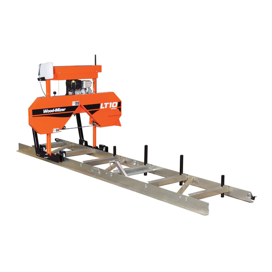
Wood-mizer LT10 User Manual
Hide thumbs
Also See for LT10:
- Safety, setup, operation & maintenance manual (100 pages) ,
- Safety, setup, operation & maintenance manual (65 pages) ,
- User manual (110 pages)
Table of Contents
Advertisement
Quick Links
Advertisement
Table of Contents

Related Manuals for Wood-mizer LT10


Summary of Contents for Wood-mizer LT10
- Page 1 Table of Contents Section-Page Table of Contents SW-07doc0425121...
- Page 3 ® Wood-Mizer Sawmill Safety, Setup, Operation & Maintenance Manual LT10S3 E7,5S rev. A2.05 Safety is our #1 concern! Read and understand all safety information and instructions before operating, setting up or maintaining this machine. December 2006 Form #794 This is the original language...
-
Page 4: Table Of Contents
Overall Dimensions ....................1-11 1.13 Components......................1-13 SECTION 2 SAWMILL ASSEMBLY Mounting Parts of LT10 Sawmills with Electric Motors .......... 2-1 Unpacking the Sawmill ..................... 2-5 Bed Frame Assembly ....................2-7 Saw Head Assembly....................2-12 SECTION 3 SETUP & OPERATION Sawmill Setup...................... - Page 5 Table of Contents Section-Page SECTION 5 TROUBLESHOOTING GUIDE Sawing Problems ....................... 5-1 SECTION 6 SAWMILL ALIGNMENT Pre-Alignment Procedures..................6-1 Preparing The Sawmill For Alignment ..............6-1 Blade Installation and Alignment................6-2 Blade Wheel Alignment .................... 6-3 Blade Guide Arm Alignment..................6-8 Aligning The Blade Guides ..................
- Page 6 Sawmill and Customer Identification Each Wood-Mizer LT10 sawmill is identified with a revision and VIN numbers. E7,5 LT10 Type Motor/Engine Basic Sawmill I.D. Revision Number Minor ”Revision” Major “Revision” Code Code VIN N EVISION AND UMBERS See the chart for VIN description.
- Page 7 114 Street, Poland at +48-63-2626000 or +48-3912-1319. From the continental U.S., call our toll-free Parts hotline at 1-800-448-7881. Please have the vehicle identification number and your customer number ready when you call. Wood-Mizer will accept these methods of payment:...
-
Page 8: Safety
It is always the owner's responsibility to comply with all applicable federal, state and IMPORTANT! local laws, rules and regulations regarding the ownership, operation and towing of your Wood-Mizer sawmill. All Wood-Mizer mill owners are encouraged to become thoroughly familiar with these applicable laws and comply with them fully while using the mill. -
Page 9: Blade Handling
Safety Blade Handling Blade Handling Always disengage the blade and shut off the sawmill engine DANGER! before changing the blade. Failure to do so will result in serious injury. Always wear gloves and eye protection when handling WARNING! bandsaw blades. Changing blades is safest when done by one person! Keep all other persons away from area when coiling, carrying or changing a blade. - Page 10 Safety Sawmill Operation Always wear eye, ear, respiration and foot protection as WARNING! well as safety clothing when operating the sawmill. Failure to do so may result in serious injury. Secure all loose clothing and jewelry before operating the WARNING! sawmill.
-
Page 11: Sawmill Maintenance
Never use grease on the mast rails as it will collect CAUTION! sawdust. See Table 1-1. Pictogram decals used to warn and inform the user about danger in the LT10. TABLE 1-1 Decal View W-M No. - Page 12 Safety Sawmill Maintenance TABLE 1-1 099219 Blade tension. Turning the bolt clockwise will increase the blade tension and turning the bolt counterclockwise will decrease the tension. 099219 099221 CAUTION! Keep all persons a safe distance away from work area when operating the machine.
- Page 13 Safety Sawmill Maintenance TABLE 1-1 096321 Blade movement direction S12004G CAUTION! Always wear safety goggles when operating the sawmill! S12005G CAUTION! Always wear protective ear muffs when operating the sawmill! 501465 CAUTION! Always wear safety boots when operating the sawmill 501467 Lubrication Point Safety...
- Page 14 Safety Sawmill Maintenance TABLE 1-1 P11789 Aligning the blade on the wheels 099226 Power feed system engagement 099226 092597 Setting the blade tension indicator 092597 P85070 CE safety certification 099401 Russian safety certification 099401 15doc042512 Safety...
-
Page 15: Belt Sizes
To insure proper blade tracking, use Goodyear, Dayco Super II, or Browning belts only. Blade Sizes See Table 1-3. Wood-Mizer TRU•SHARP™ offers three types of blades to provide efficient sawing for all models of sawmills. The engine/motor size of your sawmill and the type of wood you saw Safety... -
Page 16: Cutting Capacity
Customer may choose preferred blade. See The Blade Handbook for blade hook angle, tooth height, and tooth set specifications. Cutting Capacity See Table 1-4. The log size capacities of the LT10 sawmills are listed below. Max. Diameter Max. Length 71 cm... -
Page 17: Noise Level
Safety Noise Level 1.10 Noise Level See Table 1-6. The average level of noise is given in table below Noise Level 83,3 dB (A) LT10E7,5 TABLE 1-6 1.11 Sawdust Extractor Specifications Always turn on the dust extractor before starting the CAUTION! machine. -
Page 18: Overall Dimensions
Safety Overall Dimensions 1.12 Overall Dimensions See Figure 1-1. The overall dimensions of the LT10 sawmills are shown below. 10_002C 2186 1950 4660 1950 6610 FIG. 1-1 1-11 15doc042512 Safety... - Page 19 Safety Overall Dimensions See Figure 1-2. The picture below shows the operator’s position. 150189a RYS. 1-2 Safety 15doc042512 1-12...
-
Page 20: Components
Safety Components 1.13 Components See Figure 1-3. The major components of the Wood-Mizer LT10 are shown below. Water Tank Blade Drive Motor Electric Box Blade Tension Handle Blade Guide Arm Handle Up/Down Crank Handle 10_001C Sawmill Frame Clamp FIG. 1-3... -
Page 21: Sawmill Assembly
SAWMILL ASSEMBLY Mounting Parts of LT10 Sawmills with Electric Motors SECTION 2 SAWMILL ASSEMBLY Mounting Parts of LT10 Sawmills with Electric Motors 2.1.1 Parts specifications Table 1: Sawmill Frame Assembly Fig. Wood-Mizer No. Description Qty. 097466-1 Plate, Frame Supporting Left... - Page 22 SAWMILL ASSEMBLY Parts specifications Table 1: 097369-1 Bed Extension - Zinc-plated 097473-1 Stop, Saw Head Zinc-plated 086035-1 Wedge Weldment, Log Taper Zinc-plated 092567-1 Upper Sprocket Cover -Painted Saw Head Assembly 086323 Plate, Left Track Wiper 086322 Plate, Right Track Wiper 093859 Operator’s Guard 086171-1...
- Page 23 Table 1: 100903-1 Sawdust Chute 097248-1 Mast Side Bracket -Painted Frame with 3-bed sections 2.1.2 Specifications of Fasteners Table 2: Wood-Mizer No. Description Qty. Sample designations of fasteners: M8 Nut M8x20 Bolt 8.4 Washer F81003-17 M10x35 Bolt F81031-2 M6-8-B Nut...
- Page 24 SAWMILL ASSEMBLY Tools Necessary for Assembling the Sawmill Table 2: F81002-23 M8x100 Bolt F81059-2 Washer, M20 Flat Zinc F81053-1 Washer, M6 Flat Zinc 095919 Cap, A 50x30 Black 097480 Pipe Cap 40x40x(3-4) F81082-1 Clamp - Plastic Hose 2.1.3 Tools Necessary for Assembling the Sawmill Table 3: Required tools Flat Wrench #8...
-
Page 25: Unpacking The Sawmill
SAWMILL ASSEMBLY Unpacking the Sawmill Unpacking the Sawmill FIG. 2-1 1. Cut the bands holding the components together. 2. Remove frame parts from the pallet. 3. Remove up/down crank from the saw head, slide on the up/down handle and secure with the pin (Part No F81045-1). - Page 26 SAWMILL ASSEMBLY Unpacking the Sawmill Locking Pin F81045-1 FIG. 2-1 4. Using the up/down crank raise the saw head. Open the box with sawmill’s equipment. 15doc042512 SAWMILL ASSEMBLY...
-
Page 27: Bed Frame Assembly
SAWMILL ASSEMBLY Bed Frame Assembly Bed Frame Assembly With all screw joints without spring lock washer or lock IMPORTANT! nylon nut, use the "LOCTITE 243" (blue, of average durability, for screw joints). 1. Mount 094513-1 outrigger legs to the frame supporting plates. See Figure 2-2. - Page 28 SAWMILL ASSEMBLY Bed Frame Assembly See Figure 2-3. M8x25 Bolt 097181-1 M8x25 Bolt 8.4 Washer 097182-1 M8 Nut M8x25 Bolt FIG. 2-3 3. Lay the frame sections end-to-end so they facing each other the correct side. Slide the sections together and using the outrigger adjusting nuts, adjust the segments position. The adjacent segments should be on the same height.
- Page 29 SAWMILL ASSEMBLY Bed Frame Assembly See Figure 2-4. FIG. 2-4 4. Fasten the segments together using the 097185-1 segments connectors, blocks and mounting bolts. See Figure 2-5. Nut, M8 Hex Nylon Zinc Lock M8x100 Bolt 8.4 Washer 097464-1 Nut, M8 Hex Nylon M8x25 Bolt Zinc Lock 097185-1...
- Page 30 SAWMILL ASSEMBLY Bed Frame Assembly 5. Assemble the log clamp to the bed rail on each bed segment, using the hex head bolts and nylon lock nuts. See Figure 2-6. 10_049a FIG. 2-6 6. Mount the bed extension (Part No 097369-1) and saw head stops (Part No 097473-1). 2-10 15doc042512 SAWMILL ASSEMBLY...
- Page 31 SAWMILL ASSEMBLY Bed Frame Assembly See Figure 2-7. Nut, M8 Hex Nylon 097185-1 Zinc Lock 8.4 Washer M8x100 Bolt 097369-1 097464-1 M8 Nut 8.4 Washer 097473-1 M8x25 Bolt FIG. 2-7 7. Each bed segment has got two side supports (Part No 097470 – long and 097472 – short). Install the log side supports as shown on the Figure 2-8.
-
Page 32: Saw Head Assembly
SAWMILL ASSEMBLY Saw Head Assembly See Figure 2-8. 097470 097472 M8x12 Bolt FIG. 2-8 Saw Head Assembly 1. Using a forklift truck or a winch with lifting capacity of minimum 500 kg, carefully lift the saw head and set it aside. Attach the winch hook to the bracket on the saw head. When removing the saw head, use extreme care and keep WARNING! all persons at a safe distance. - Page 33 SAWMILL ASSEMBLY Saw Head Assembly See Figure 2-9. 500kg FIG. 2-9 1. Position the saw head at the end of the bed frame assembly. Carefully slide the saw head rollers onto the bed frame track. Keep the saw head square to the bed to avoid jamming the track rollers. When setting the saw head on the bed frame, use extreme WARNING! care and keep all persons at a safe distance.
- Page 34 SAWMILL ASSEMBLY Saw Head Assembly See Figure 2-10. M8x12 Bolt Track Wiper (086322) M8x12 Bolt Track Wiper (086322) M8 Nut 8.4 Washer Latch M8x30 Bolt (097567-1) FIG. 2-10 Before installing the track cover and the remaining felt wipers, soak the felt strips with NOTE: lubricating fluid (e.g.
- Page 35 SAWMILL ASSEMBLY Saw Head Assembly See Figure 2-11. M8x16 Bolt 8.4 Washer 10_052c 100903-1 FIG. 2-11 4. Install the operator guard. See Figure 2-12. M8x16 Bolt M8x25 Bolt Nut, M8 Hex Nylon Zinc Lock 8.4 Washer 10_055a M10x50 Bolt Guard (093859) 10.5 Washer M8x20 Bolt FIG.
- Page 36 SAWMILL ASSEMBLY Saw Head Assembly 5. Install the blade guides. See Figure 2-13. Blade Guide (094682) Blade Guide (094683) M10x1x25 Bolt Nut, M10x1 Thin (8) Screw, M10x1x20 (7) FIG. 2-13 6. Install the power cord bracket. 2-16 15doc042512 SAWMILL ASSEMBLY...
- Page 37 SAWMILL ASSEMBLY Saw Head Assembly See Figure 2-14. Holder, Plastic Cable Tie Screw, M4x16 (F81082-1) Power Cord Bracket 086132-1 M4 Nut 4.3 Washer FIG. 2-14 SAWMILL ASSEMBLY 15doc042512 2-17...
-
Page 38: Setup & Operation
Setup & Operation Sawmill Setup SECTION 3 SETUP & OPERATION Sawmill Setup Before starting to use the sawmill you have to meet the IMPORTANT! following conditions: Set up the sawmill on firm, level ground and level the sawmill. Secure the sawmill to the ground to prevent moving during operation. - Page 39 Setup & Operation Sawmill Setup The following setup procedure should be performed whenever the sawmill is moved or NOTE: reassembled. If sawing problems occur and misalignment is suspected, See Section SECTION 6 complete alignment instructions. 1. Adjust the frame legs so the sawmill appears level. If sawmill is on soft ground, use shims under the legs if necessary.
- Page 40 Setup & Operation Sawmill Setup mounting bolts of the roller bracket. Use the saw head adjustment nuts located in the roller bracket to tilt the saw head. Lock Nut Roller Bracket Mounting Bolts (4) Adjustment Nuts FIG. 3-2 8. Make sure the entire face of each slide pad makes contact with the mast. Use the adjustment nuts 15doc042512 Setup &...
- Page 41 Setup & Operation Sawmill Setup shown below to adjust the slide pads if necessary. Slide Pad Adjustment Nuts FIG. 3-3 9. Check the vertical alignment of each blade wheel using the blade guide alignment tool. Attach the tool to the blade near the outer blade guide. Be sure the tool does not rest on a tooth or burr, and is lying flat on the blade.
- Page 42 Setup & Operation Sawmill Setup Move the saw head so the front end of the tool is positioned over the first bed rail. Measure from the bottom of the tool to the top surface of the bed rail. Move the saw head so the rear of the tool is positioned over the bed rail. Again, measure from the bottom of the tool to the bed rail.
- Page 43 Setup & Operation Sawmill Setup See Figure 3-6. To tilt the drive-side blade wheel down, loosen the top adjustment screw, loosen the nut on the bottom adjustment screw and tighten the bottom screw. Tighten the top and bottom nuts. To tilt the wheel up, loosen the bottom adjustment screw, loosen the nut on the top adjustment screw and tighten the top screw.
- Page 44 Setup & Operation Sawmill Setup guides and adjust if necessary. 13. Install the blade height scale. To do that, first measure the distance from the bottom edge on a down-set tooth of the blade to the top of the bed rail. Then stick the blade height scale on the mounting bracket so that it indicates the true distance from the blade to the bed.
- Page 45 Setup & Operation Sawmill Setup stops moving at its lower travel limit, i.e. at the height of 25 mm above the bed. Loosen the nut and adjust the stop bolt FIG. 3-8 16. Adjust the side bracket. See Section 6.13. Adjust the side bracket before first operating the sawmill.
-
Page 46: Replacing The Blade
Setup & Operation Replacing The Blade Replacing The Blade Always disengage the blade and shut off the sawmill motor DANGER! before changing the blade. Disconnect the power supply using the main switch. Failure to do so will result in serious injury. Always wear gloves and eye protection when handling WARNING! bandsaw blades. -
Page 47: Tensioning The Blade
Setup & Operation Tensioning The Blade Tensioning The Blade See Figure 3-9. Turn the blade tension handle clockwise to compress the rubber spring and tension the blade. Check the blade tension occasionally when adjusting the cant control or while cutting. As the blade and belts heat up and stretch, the blade tension will change. -
Page 48: Tracking The Blade
Setup & Operation Tracking The Blade Tracking The Blade 1. Make sure the blade housing cover is closed and all persons are clear of the blade. 2. Start the motor for a moment until the blade positions itself on the wheels. Do not spin the blade wheels by hand. - Page 49 Setup & Operation Tracking The Blade See Figure 3-11. To adjust where the blade travels on the blade wheels, use the cant control bolt. Cant Control Bolt FIG. 3-11 If the blade is too far out, back the blade onto the wheel by turning the cant control counterclockwise. If the blade is too far in, turn the cant control clockwise until the gullet of the blade is the correct distance from the front edge of the wheel.
-
Page 50: Loading, Turning, And Clamping Logs
Setup & Operation Loading, Turning, And Clamping Logs Loading, Turning, And Clamping Logs To Load Logs 1. Move the cutting head to the front end of the frame. Before loading a log, be sure the cutting head is moved far CAUTION! enough forward so the log does not hit it. - Page 51 Setup & Operation Loading, Turning, And Clamping Logs See Figure 3-13. 10_007a FIG. 3-13 6. Position the log at the foot of the ramps. 7. Use a cant hook to roll the log up the ramps and onto the sawmill bed. Position the log against the side supports.
- Page 52 Setup & Operation Loading, Turning, And Clamping Logs See Figure 3-14. 10_008a FIG. 3-14 2. Make sure the side supports are positioned low enough for the blade to pass over them. If they are not, back the clamps off slightly and push the side supports down until they are positioned below the height of your last cut on a given side of the log.
-
Page 53: Up/Down Operation
Setup & Operation Up/Down Operation log until the heart of the log measures the same distance from the bed rails at each end of the log. Leveling Wedge Level log so heart is same 10_009a distance from bed rails at both ends FIG. -
Page 54: Blade Guide Arm Operation
Setup & Operation Blade Guide Arm Operation See Figure 3-15. Use the up/down crank to raise or lower the cutting head. To raise the saw head turn the crank handle clockwise; to lower – turn the crank handle counterclockwise. Pull the handle grip, to engage the up/down drive. - Page 55 Setup & Operation Blade Guide Arm Operation See Figure 3-16. 150120 Move the handle right to move the blade arm out. Move it left to move the blade guide in. FIG. 3-16 Setup & Operation 15doc042512 3-18...
-
Page 56: Blade Drive Operation
Setup & Operation Blade Drive Operation Blade Drive Operation When starting the machine for the first time, check that IMPORTANT! main motor rotation direction is as indicated by the arrow located on the motor body (fan guard). If the rotation direction is incorrect, invert the phases in the phase inverter located in the power socket (electric box). - Page 57 Setup & Operation Blade Drive Operation Switch, Switch, Emergency Start-Stop Stop Main Switch Safety Handle FIG. 3-16 If at any time you need to immediately stop the blade CAUTION! motor, press the emergency stop button located on the electric box. Setup &...
-
Page 58: Feed Operation
3.10 Cutting The Log The following steps guide you through normal operation of the Wood-Mizer sawmill. 1. Once the log is placed where you want it and clamped firmly, position the blade close to the end of the log. -
Page 59: Edging
(25 mm) thick boards, lower the carriage 1 1/16 - 1 1/8" (27 - 29 mm) for each board. 3.11 Edging The following steps guide you through edging boards on the Wood-Mizer sawmill. 1. Raise the side supports to 1/2 the height of the flitches, or the boards that need to be edged. -
Page 60: Blade Height Scale
Setup & Operation Blade Height Scale 3.12 Blade Height Scale See Figure 3-17. The blade height scale is mounted on the vertical mast. It includes: a blade height indicator centimeter scale (or quarter inch scale) Scale Blade Height Indicator 150028C FIG. - Page 61 Setup & Operation Blade Height Scale The Standard Quarter Scale allows for kerf and shrinkage of finished boards suitable for most custom applications. Always check with your customer before you saw to determine what actual finished thickness is required. Standard Quarter Scale Grade Hardwood Quarter Scale Scale Actual Board Thickness...
-
Page 62: Water Lube Operation
Setup & Operation Water Lube Operation 3.13 Water Lube Operation The Water Lube System keeps the blade clean. Water flows from a 5 liter bottle through a hose to the blade guide where the blade enters the log. A valve in the bottle cap controls the amount of water flow. -
Page 63: Transporting The Sawmill
Setup & Operation Transporting the Sawmill See Figure 3-19. Open the valve on the water bottle to start water flow on the blade. To close turn valve clockwise; to open turn valve counterclockwise. FIG. 3-19 Not all types of wood require the use of the Water Lube System. When it is needed, use just enough water to keep the blade clean. - Page 64 Wood-Mizer LT10 Short Interval Maintenance Schedule PROCEDURE MANUAL REFERENCE EVERY BLADE CHANGE Check Blade Guide Roller Performance SEE SECTION 4.2 Remove Excess Sawdust From Blade Wheel Housings And Sawdust Chute SEE SECTION 4.2 EVERY 8 HOURS Clean And Lubricate Track SEE SECTION 4.3...
- Page 65 WOOD-MIZER LT10 MAINTENANCE LOG PROCEDURE MANUAL TOTAL HOURS OF OPERATION REFERENCE FILL IN THE DATE AND THE MACHINE HOURS AS YOU PERFORM EACH PROCEDURE. A SHADED BOX INDICATES MAINTENANCE IS NOT NEEDED AT THIS TIME. 50 HRS 100 HRS 150 HRS...
- Page 66 WOOD-MIZER LT10 MAINTENANCE LOG PROCEDURE MANUAL TOTAL HOURS OF OPERATION REFERENCE FILL IN THE DATE AND THE MACHINE HOURS AS YOU PERFORM EACH PROCEDURE. A SHADED BOX INDICATES MAINTENANCE IS NOT NEEDED AT THIS TIME. 1050 HRS 1100 HRS 1150 HRS...
- Page 67 WOOD-MIZER LT10 MAINTENANCE LOG PROCEDURE MANUAL TOTAL HOURS OF OPERATION REFERENCE FILL IN THE DATE AND THE MACHINE HOURS AS YOU PERFORM EACH PROCEDURE. A SHADED BOX INDICATES MAINTENANCE IS NOT NEEDED AT THIS TIME. 2050 HRS 2100 HRS 2150 HRS...
-
Page 68: Maintenance
Wear Life SECTION 4 MAINTENANCE This section lists the maintenance procedures that need to be performed on the LT10 sawmills. The Short Interval Maintenance Schedule lists procedures that need to be performed every 4, 8 or 25 hours.The Maintenance Log lists procedures that need to be performed every 50, 100, 200, or 1000 hours. -
Page 69: Vertical Mast Rails
Maintenance Vertical Mast Rails any sawdust buildup from the housings. Track Roller Housing Scrappers FIG. 4-1 Vertical Mast Rails Clean and lubricate the vertical mast rails every 50 hours of operation. Clean with solvent and remove any rust with a light-grade sand paper. Lubricate the mast with motor oil or automatic transmission fluid (e.g. -
Page 70: Blade Wheel Belts
Maintenance Blade Wheel Belts See Figure 4-2. Grease the blade tensioner thread FIG. 4-2 Blade Wheel Belts 1. Check the blade wheel belts for wear. Replace belts as necessary. Rotating the belts every 50 hours will give you longer belt life. Use only B57 belts manufactured by Goodyear or Browning. 2. -
Page 71: Miscellaneous Maintenance
Order decals from your Customer Service Representative. Safety Devices Inspection LT10 – Safety Devices Inspection Safety devices on the LT10 machine which must be checked before every shift: E-STOP button and its circuit inspection Safety handle and its circuit inspection Blade cover safety switches and its circuit inspection. - Page 72 Maintenance Safety Devices Inspection Switch, Switch, Motor Emergency Start-Stop Stop Safety Handle 2. Safety handle and its circuit inspection Be sure the E-STOP button is released; Press and hold the safety handle; Turn on the blade motor; Release the safety handle. The blade motor should be stopped. Press and hold the safety handle.
-
Page 73: Troubleshooting Guide
Troubleshooting Guide Sawing Problems SECTION 5 TROUBLESHOOTING GUIDE Sawing Problems PROBLEM CAUSE SOLUTION Dirty logs Clean or debark logs, especially on Blades Dull Quickly entry side of the cut. When grinding teeth, heating too much Grind just enough metal and causing teeth to soften to restore sharpness to the teeth. - Page 74 Troubleshooting Guide Sawing Problems PROBLEM CAUSE SOLUTION Stress in log which causes log to not After log has been squared, take equal Boards Thick Or Thin On lay flat on the bed cuts off opposing sides. Repeat, Ends Or Middle Of Board keeping the heart in the middle of the cant, and making it your last cut.
-
Page 75: Sawmill Alignment
Sawmill Alignment Pre-Alignment Procedures SECTION 6 SAWMILL ALIGNMENT Pre-Alignment Procedures Periodically check the sawmill alignment and adjust if necessary. This chapter explains how to align the entire sawmill. Care should be taken in performing these steps. Sawmill alignment determines the accuracy and squareness of your cuts. The sawmill alignment steps are: 1. -
Page 76: Blade Installation And Alignment
Sawmill Alignment Blade Installation and Alignment Blade Installation and Alignment Install a blade and apply the appropriate tension as shown in Section 3.3. 1. Close the blade housing cover and make sure all persons are clear of the open side of the saw head. 2. -
Page 77: Blade Wheel Alignment
Sawmill Alignment Blade Wheel Alignment Blade Wheel Alignment The blade wheels should be adjusted so they are level in the vertical and horizontal planes. If the blade wheels are tilted up or down, the blade will want to travel in the tilted direction. If the blade wheels are tilted horizontally, the blade will not track properly on the wheels. - Page 78 Sawmill Alignment Blade Wheel Alignment See Figure 6-3. Use the vertical adjustment screws to adjust the drive-side blade wheel. To tilt the wheel down, loosen the top adjustment screw half turn. Loosen the jam nut on the bottom adjustment screw and tighten the screw. Tighten the top and bottom jam nuts. To tilt the wheel up, loosen the bottom adjustment screw half turn.
- Page 79 Sawmill Alignment Blade Wheel Alignment adjustment screw and tighten the screw. Tighten the top and bottom jam nuts. FIG. 6-4 8. Re-check the vertical tilt of the idle-side blade wheel. Readjust if necessary. 9. Check the position of the blade on the idle-side blade wheel. See Figure 6-5.
- Page 80 Sawmill Alignment Blade Wheel Alignment See Figure 6-6. Use the cant control adjustment, shown on the figure below, to adjust the idle-side blade wheel. If the blade is too far forward on the wheel, turn the cant control counter clockwise. If it is too far back on the wheel, turn the cant control clockwise.
- Page 81 Sawmill Alignment Blade Wheel Alignment adjustment screw to move blade in on wheel. Tighten the jam nut. Adjustment screw FIG. 6-7 11. Adjust the blade vibration damper screw. Distance from the screw to the blade should be about 1mm. See Figure 6-8. FIG.
-
Page 82: Blade Guide Arm Alignment
Sawmill Alignment Blade Guide Arm Alignment Blade Guide Arm Alignment Before aligning the blade guide arm, track the blade on the blade wheels as described in Section 3.4. Move the cutting head so the blade is positioned over the first bed rail. Level the blade to the bed rail as shown in 3.1. - Page 83 Sawmill Alignment Blade Guide Arm Alignment Horizontal Alignment See Figure 6-10. 1. With the blade guide arm still all the way in toward the other blade guide, tighten all the side screws until they touch the arm. Back the screws off 1/4 turn and tighten the jam nuts. 2.
-
Page 84: Aligning The Blade Guides
Aligning The Blade Guides Aligning The Blade Guides Each Wood-Mizer sawmill has two blade guide assemblies that help the blade maintain a straight cut. The two blade guide assemblies are positioned on the saw head to guide the blade on each side of the material being cut. -
Page 85: Blade Guide Vertical Tilt Adjustment
Sawmill Alignment Blade Guide Vertical Tilt Adjustment 2. Loosen the bottom jam nut and tighten the top jam nut until the blade guide deflects the blade down 1/4" (6 mm). 3. Repeat for the other blade guide. Be sure that the blade guard clears the blade on both guide assemblies. The guard on the NOTE: outer guide assembly should be checked with the arm all the way in and all the way out. - Page 86 Sawmill Alignment Blade Guide Vertical Tilt Adjustment See Figure 6-13. Loosen jam nuts and turn screws to tilt roller up or down SM0070 FIG. 6-13 7. Move the carriage forward so the back end of the tool is over the bed rail. 8.
-
Page 87: Blade Guide Flange Spacing
Sawmill Alignment Blade Guide Flange Spacing Blade Guide Flange Spacing HINT: When adjusting blade guide flange spacing, loosen the top set screw and one side set screw only. This will insure horizontal and vertical tilt adjustments are maintained when the set screws are retightened. -
Page 88: Horizontal Tilt Adjustment
Sawmill Alignment Horizontal Tilt Adjustment 6.10 Horizontal Tilt Adjustment 1. Move the blade guide arm half way in. See Figure 6-15. FIG. 6-15 2. Place Blade Guide Alignment Tool against the face of the outer blade guide roller, as shown above. 3. -
Page 89: Blade Height Scale Adjustment
Sawmill Alignment Blade Height Scale Adjustment 6.11 Blade Height Scale Adjustment Standard Scale After the entire sawmill has been aligned and all adjustments made, check that the blade height scale indicates the true distance from the blade to the bed rails. See Figure 6-16. - Page 90 Sawmill Alignment Blade Height Scale Adjustment See Figure 6-17. Loosen indicator bracket mounting bolts Loosen scale bracket mounting bolt Loosen scale bracket mounting bolts FIG. 6-17 2. Move the saw head so the blade is positioned directly above one of the bed rails. Measure from the bottom edge on a down-set tooth of the blade to the top of the bed rail.
-
Page 91: Motor Drive Belt Adjustment
Sawmill Alignment Motor Drive Belt Adjustment 6.12 Motor Drive Belt Adjustment See Figure 6-18. Loosen the motor mounting bolts. Using the adjustment bolts shown below, adjust the drive belt until it has 7/16" (11 mm) deflection with a 8 lbs (3.6 kG) deflection force - in the case of E11 motor or 7/16"... -
Page 92: Mast Side Bracket Adjustment
Sawmill Alignment Mast Side Bracket Adjustment 6.13 Mast Side Bracket Adjustment To prevent saw head mast from tilting, the side bracket should be adjusted properly. Use the adjustment bolt, and adjust it so the distance between bolt head and bed rail is about 1mm. Side Bracket Adjustment Bolt 10_024a... -
Page 93: Safety Handle Linkage Adjustment
Sawmill Alignment Safety Handle Linkage Adjustment 6.14 Safety Handle Linkage Adjustment See Figure 6-19. Use the adjustment nuts to adjust linkage tension so the blade stops during 8 seconds after the safety handle is released. Adjustment Nuts FIG. 6-19 Sawmill Alignment 15doc042512 6-19... - Page 94 EC declaration of conformity according to EC Machinery Directive 2006/42/EC We herewith declare, Wood-Mizer Industries sp. Z O.O. 114 Nagorna street, 62-600 Kolo; Poland. That the following described machine in our delivered version complies with the appropriate basic safety and health requirements of the EC Machinery Directive 2006/42/EC based on its design and type, as brought into circulation by us.
Need help?
Do you have a question about the LT10 and is the answer not in the manual?
Questions and answers